APLOS R0-N5050 User manual

Instruction Manual
5 Stage Reverse Osmosis
Drinking Water System, 50gpd
Manufactured for EPS Group
aplos.ie

Contents
1Introduction 3
2Feed Water and Operations Requirements 4
3Product Specication 5
4Installation Diagram 7
5Installation Instructions 8
6Installation Steps 9
7Operational Guidelines 13
8Filter Replacement Guide 14
9Membrane Replacement Guide 15
10 Troubleshooting 16
11 Warranty 18
Table of Contents
Section Pages

1. Introduction
This drinking water system utilizes most advanced renowned reverse osmosis
technology to purify water. It relies on the arti cial reversing of the naturally oc-
curring osmosis phenomena. The reverse osmosis membrane with a pore size of
0.0001 micron (0.1 nm), can effectively reduce bacteria, viruses, heavy metals,
pesticide residue, lead, uoride and other harmful substances. Produced water is
fresh, pure and suitable for direct use.
NOTE:
Please read through the instructions carefully before using or installing the
product. Ensure that the manual is kept in a safe place for reference.
The system must be properly installed and serviced in accordance with the in-
structions. We recommend that the system is installed by a trained professional.
For households with inlet water pressure
<3 bar
Unpumped Model R0-N5050
For households with inlet water pressure
from 3-6 bar
3
Pumped Model R0-5050

To achieve the optimal performance, it is highly recommended to use this system
within the following operational parameters.
*If feed water pressure is below the requirements, pumped reverse osmosis should
be installed. If the feed water pressure is above the limits pressure valve needs to
be installed on the mains supply.
**It is needed to pump up or release the pressure if it is outside the limits
1Hydrogen Ion (pH) 6.5 - 8.5
2TDS <1500 ppm
3Hardness <500 ppm CaCO3
4Free Chlorine <0.5 ppm
5Iron <0.3 ppm
6Manganese <0.1 ppm
7Chemical oxygen demand <5 ppm O2
8Total bacterial count <50 CFU/mL
9E. coli <3
Feed Water Quality Requirements
1Water Supply Municipal or pre-treated
well water
2Main Pressure (no booster pump), bar 3 - 6
3Main Pressure (booster pump installed), bar 2 - 4.5
4Pressure Tank, bar 0.4 - 0.6*
5Inlet Water Temperature, °C +4 - +30**
6Water Supply Connection 1/2” Thread
7Product dimensions, HxWxD
(basic assembly) mm 350x450x150
NOTE:
Do not use with water that is microbiologically unsafe or of unknown quality
without adequate disinfection before or after the system.
If water supply does not meet the requirements, service life of membrane and/or
pre-lter cartridges may be shortened.
2. Feed Water and Operations Requirements
4

3. Product Specication
Carbon Post-Filter
Auto shut-off valve
Membrane Housing
Filter Head
Housing
5
Booster Pump
1) System Rack
Options:
2) Pressure Tank 3) Drinking Water Faucet 4) Feed Water Adapter

5) Feed Valve 6) Tank Valve 7) Set of
coloured tubes
8) Drain Saddle
9) Set of pre-lter cartridges
PP5 GAC PP1
10) Housing
Wrenches
11) Reverse Osmosis
50 GDP membrane
12) Flow Restrictor 13) Locking clip: accessory securing push-t
connections from inadvertent disconnection
in easily accessible locations
3. Product Specication
6

4. Installation Diagram
Red Tube
Black Tube
Blue Tube
Yellow Tube Yellow Tube
Black Tube
Blue Tube
Red Tube
1) Model RO-N5050 Non Pumped 5-Stage Reverse Osmosis Drinking System
2) Model RO-5050 Pumped 5-Stage Reverse Osmosis Drinking System
220V
7

BEFORE INSTALLATION CAREFULLY READ INSTRUCTIONS
This product should be used with cold water supply only!
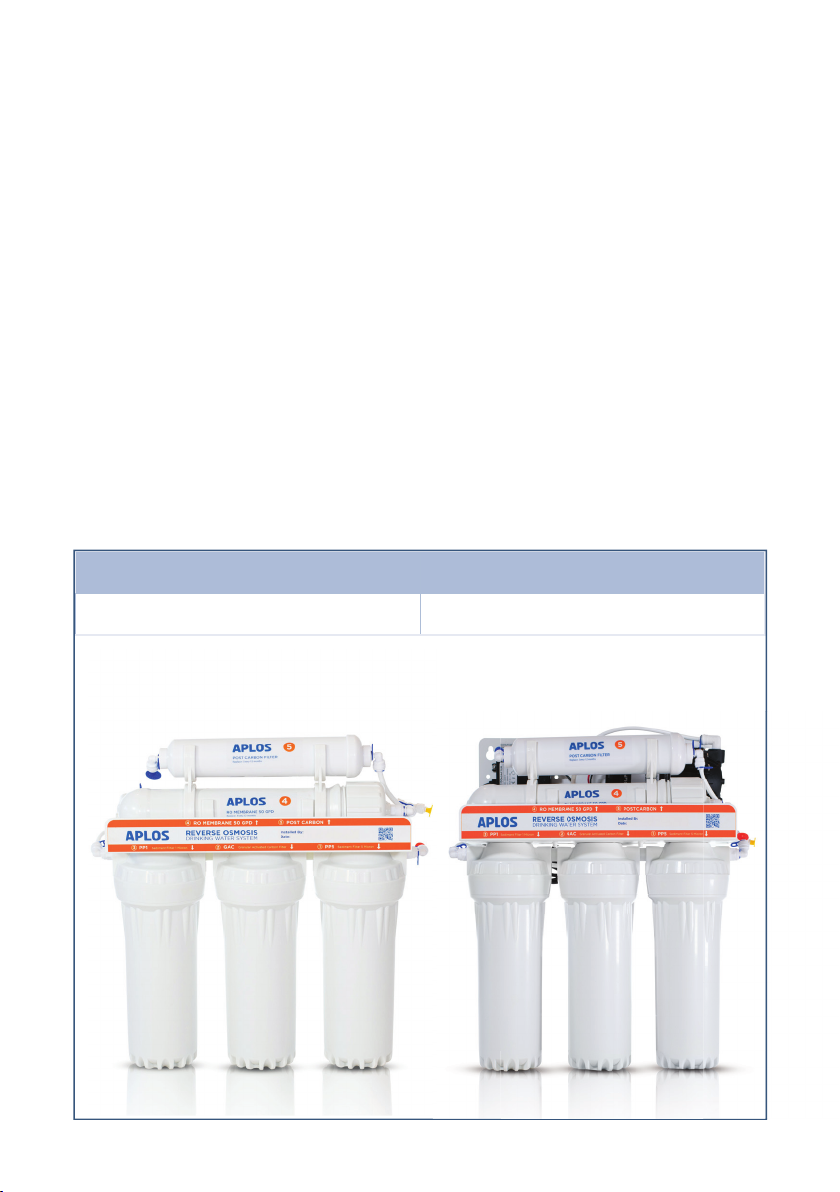
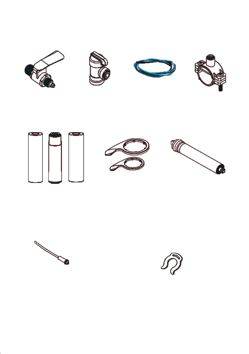
1) Check that all parts are in the package.
2) Before installation, please check incoming water pressure, tank pressure and
inlet water temperature. In certain installations the use of a PRV valve and surge
vessel may be required.
3) Make sure feed water quality complies with the requirements from section 2. If
feed water quality does not meet the requirements, consult with a water treatment
specialist.
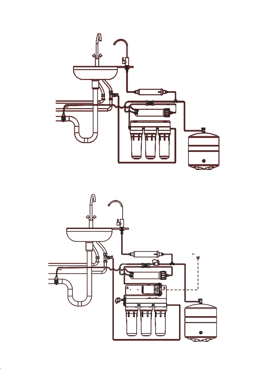
4) Before installing the system, make sure there is enough space for both the lter
rack and the pressure tank under the sink. In case there is not enough available
space, pres- sure tank can be placed in separately. Yellow tube’s length is sufcient
to connect it to the rest of the system.
5) Electrical safety notice: This appliance should be connected into a circuit with
an RCB installed. Please note voltage requirements. The unit is to be supplied with
single-phase 230 VAC, 50 Hz electrical power.The system is supplied with power
cord and can be connected to a properly installed IEC 60884-1 compliant socket.
6) Once installation has been completed and operational ensure that all ttings,
pipework, and unit has been checked for any drips and leakage.
Always ensure unit is tted in a safe and correct manner as outlined by this manual
NOTE:
This system has been tested by the manufacturer for leaks, so within the
system the presence of residual water is allowed. This system should be in
-
stalled away from direct sunlight and heating appliances.
5. Installation Instructions
8

1Shut off water supply in your kitchen or whole home and open water tap
where you are about to install the system (on your kitchen sink) for 1 min-
ute to relieve pressure in the system, and then close it.
2Screw the feed water adapter 4into the cold water plumbing. Screw the
feed valve 5into the feed water adapter 4. To help prevent water leaks use
plumber sealing tape.
3Unscrew the compression nut from the feed valve 5and put it on the red
tube. Push the red tube on the end of feed valve’s tting and screw on the
compression nut. Connect the free end of the red tube with the quick con-
nect tting of the rst (rightmost) housing in the rack.
4Connect the drain saddle 8 with drain pipe from the kitchen sink. The drain
saddle is compatible with most standard drain pipes. Drill a hole of 5.0
mm (0.2”) diameter in the kitchen sink drain pipe, apply rubber gasket
with sticky base (included in the package). Install the drain saddle 8 on the
drain pipe over the hole. Tighten screws on drain saddle with a screwdriver.
Insert black tube into the connection on the clamp (gure 4). Connect the
other end of the black tube with concentrate outlet of membrane housing.
CAUTION! Check if the ow regulator 12 is installed in the black tube in
the end connected to membrane housing.
5Add 5-6 wraps of plumber tape to tank knob and hand tighten tank valve –
do not overtighten. Close the tank valve.
IMPORTANT! Check air pressure in empty tank. Tank should be pressur-
ized to 0.4-0.6 bar (5.8-8.7 psi). If necessary, use a pump with a pressure
gauge to increase the pressure or push the core of the valve stem to
relieve pressure.
6. Installation Steps
9

6
To install drinking water faucet drill 12.5 mm (1/2”) diameter hole for single
way tap in a convenient location at the sink or countertop.
Caution! metal shavings can damage your unit, remove them carefully as
soon as you have drilled the hole. If the mounting surface is ceramic or
stone, you may need a special carbide drill.
Mount the faucet on the sink or countertop as shown on the gure. Nut,
lock washer and plastic washer on the faucet shank must x the faucet
rmly on the surface.
Take the blue tube, put on compression nut, ferrule, and put plastic insert
inside, in that order.
Push the blue tube as deeply as possible into the bottom of the faucet’s
shank, ensuring the compression ring is in the joint. Screw on the
compression nut in order to join the tube to the faucet.
Tap Installation
6.1
6.2
6.3
6.4
6. Installation Steps
10

7Select spot where you are going to install the lter andmake two holes.
The distance between the holes in the wall must precisely correspond to
that between the holes in the bracket. Allow for at least 100 mm (3.9”) gap
between the bottom of the lter and oor. Install screw anchors if neces-
sary and screw in two screws (not included).
The distance between the holes is 272 mm (10.7”).
8Insert cartridges into the rst and the second housings in the direction of
water ow (leftwards).
9Tighten all the three sumps by hand.
10 Unplug the tube that connects the third housing (in the direction of water
ow) with the auto shut-off valve from the valve.
11 Open the water tap 5 and let through the rst two pre- lters with cartridg-
es 5-7 liters (1.5-2 gallons) of water to wash off the carbon nes (black in
colour) that may appear in cartridges during shipping. Then close feed
water valve before installing the third cartridge.
CAUTION! This water will pour through the tube disconnected from auto
shut-off valve, prepare a vessel to collect it.
12 Insert the cartridge into the third housing along water ow direction and
attach the housing back again. Connect the free end of the tube back to
the auto shut-off valve.
Install the membrane 11 into the membrane housing.
CAUTION! Cut the plastic bag to install the reverse osmosis membrane.
Install the membrane without rst unpacking it by pushing it into the
housing directly from the bag. Avoid touching the membrane and only
hold it covered with the bag.
13
6. Installation Steps
272 mm (10.7”)
11

Leave the feed valve 5 and puried water faucet 3 open for 30 minutes.
Then open the tank valve 6. Close the faucet 3 and carefully check all
connections for leaks.
CAUTION! The rst week after installation, check the system daily for
leaks, do it periodically in the future. If you are leaving for a long time
such as for a business trip or vacation, shut off the water supply.
Let the water tank get lled (you will hear the water stop owing). De-
pending on the water pressure in your water mains may take 1.5 to 3 hours.
After that drain all water from the tank by opening the faucet 3until the
ow goes to a drip or slow dribble. After the tank has been emptied, close
the faucet 3 so that the tank starts re-lling. Depending on the pressure
in your water mains, it may take 1.5 to 3 hours. After the tank is lled for
the second time, you can use puried water. In the models of lters with a
mineralizing post-lter the puried water can be slightly turbid after instal-
lation. Drain several additional tanks of puried water.
Initially your water may appear cloudy which is due to air in the system.
If you leave the glass of water for a few minutes, the water will become
clear as the air escapes. This is normal and will eventually clear as the air is
eventually ushed out of the lters.
15
16
A(1.1) A
14
6. Installation Steps
12

When using the system for the rst time, let puried water drain from the full
water pressure tank.
It is highly recommended to replace lter cartridges regularly to ensure high
quality of water purication.
It is recommended that you use the system at least twice a week to prevent
microbiological contamination caused by the equipment lying idle for an extended
period of time, which in turn might cause odors in the water.
If you did not use the system for a longer period (more than a week),
before using puried water, follow the below steps:
1) turn off water inlet
2) cut off electricity
3) empty the water storage tank
4) turn on the inlet water and electricity
The system will begin reverse osmosis purication. If you did not use the system
for long periods (i.e 1-2 months), replace the lters before using the machine.
7. Operational Guidelines
Stage 1 Sediment Filter PP5 6 months
Stage 2 Granular Activated Carbon Filter GAC 6 months
Stage 3 Sediment Filter PP1 6 months
Stage 4 RO Membrane 12 months
Stage 5 Post Carbon Filter 12 months
Recommended Filter Replacement Schedule
13

8. Filter Replacement Guide
Shut off feed valve 5and tank valve 6.
CAUTION! Dissemble while under water pressure can result in ooding!
Wash your hands with antibacterial soap.
Unscrew with the sump wrench 10 rst and second sumps in water ow
direction (right to left). Be careful as the sumps are lled with water.
Remove the used lter cartridges.
Wash housings with soap and a clean sponge, then rinse
thoroughly with water.
Insert the new cartridges in the rst and second sumps by water ow
direction.
Disconnect the tube stemming from the third sump from the auto
shut-off valve.
Open the feed valve 5 and let through the rst two installed cartridges 5-7
liters (1.5-2 Gallons) of water to rinse the
coal dust that may be produced in cartridges during shipping.
CAUTION! This water will pour through the tube disconnected from auto
shut-off valve, prepare a vessel to collect it.
Remove the third pre-lter’s sump from lter head. Be careful as it is lled
with water.
Remove the used lter cartridge and wash the sump with unavored soap
and a clean sponge, then rinse thoroughly
with water.
Insert new cartridge into the third sump. Screw the sump back on and let
through at least 4 more liters of water to ush the coal dust. Close the feed
valve 5 and connect the previously separated tube with the auto shut-off
valve.
Open the tank valve 6.
Open the feed valve 5.
6.
1.
2.
3.
4.
5.
7.
8.
9.
10.
11.
12.
13.
14

9. Membrane Replacement Guide
Turn off water supply to the system (feed valve 5), shut off the tank valve 6.
Open the puried water faucet 3 to relieve permeate pressure.
Disconnect the white tube from the inlet in membrane housing cap.
Unscrew the membrane housing cap.
Remove the used reverse osmosis membrane 11 (remember which end of
the membrane goes where).
Lubricate rubber seals of the fresh replacement membrane and
membrane housing cap sealing.
CAUTION! To avoid damage to the membrane, only use food grade
glycerol as lubricant.
Install the fresh membrane into the housing, observing its direction and
position of the tube.
CAUTION! Ensure to wear latex gloves when installing the reverse
osmosis membrane. Avoid direct contact with the membrane.
Screw on the housing cap.
Connect the white tube to the membrane housing inlet.
Close drinking water faucet 3.
Open the tank valve 6.
Open the feed valve 5.
Once the tank is full (you will hear the water stop owing), drain all water
from the tank into the sink by opening faucet 3. When the water stops
running, close the puried water faucet 3 so that the tank starts to re-ll.
Depending on the pressure in your water mains, lling may take 1.5 to 3
hours. After the second tank re-ll, you can safely use the puried water.
1.
2.
3.
4.
5.
Membrane
Cap of the membrane housin
White Tube
6.
7.
10.
9.
8.
11.
12.
13.
15

Fitting leak Tube is not joined tightly Remove and rejoin the tube
Drain saddle leak Drain saddle is not in-
stalled
properly
Reinstall drain saddle as
described in paragraph 4.2
in this manual
Pre-lter sump leak O-ring seal is missing or
misaligned
Check that the O-ring seal
is properly aligned in the
groove inside sump
Housing is not joined
tightly
Tighten the housing till snug
Water runs too slowly
from the faucet or slows
down substantially a
few seconds after the
faucet is opened
Pre-lter cartridges are
clogged
Replace pre-lter cartridges
Membrane is clogged Replace the membrane
A tube is kinked Straighten the tube
Pressure tank is deated Pressure in the empty tank
should be 0.4-0.6 bar (6-9
psi). Charge the tank to the
above pressure
High noise Air in the auto shut off
valve
The problem will remedy
itself after a while in
operation.
Water supply pressure
too high
Check your water supply
pressure. If necessary, install
a pressure gauge or
contact a specialist
Auto shut-off valve is
making noise
Pressure surges in water
mains
Install a check valve on the
main pipe in your kitchen or
at the point of entry of your
home’s water supply. Con-
tact a specialist
Problem Cause Solution
10. Troubleshooting
16

10. Troubleshooting
The system is constantly
in operation mode
(water is drained
continuously)
Pre-lter cartridges are
clogged
Replace pre-lter cartridges
Membrane is clogged Replace membrane
Missing or misplaced
ow restrictor
Flow restrictor must be
installed in the tube running
from membrane housing to
drain. Flow restrictor must
face membrane housing. If
it faces drain saddle tting,
clean it and swap ends of
the tube so that it is placed
at the outlet of membrane
housing. If ow restrictor
was not installed, install one
Failure of auto shut-off
valve.
The RO system operating
ceaselessly while the tank is
full may be due to automat-
ic shut-off valve failure.
Failure of check valve in
the transition tting in-
stalled at membrane
housing permeate outlet
Pressure in the empty tank
should be 6-9 psi (0.4...0.6
bar). Pump the tank to the
above pressure if necessary
Pressure tank is deated Open drinking water faucet
and let some water out. It
is normal for the system to
stand idle when the pressure
tank is full of water
The system will not turn
on (no water runs to
sink drain)
Pressure tank is full Open drinking water faucet
and let some water out. It
is normal for the system to
stand idle when
the pressure tank is full of
water.
Flow restrictor is clogged Clean or replace ow re-
strictor
Drain saddle tting is not
centered
on drain pipe hole
Correctly position the drain
saddle
Problem Cause Solution
17

We hope that this product will serve you long and let you and your family enjoy
high quality pure drinking water.
Product warranty period is 12 months from the date of purchase.
We guarantee that reverse osmosis water drinking system does not contain
workmanship and material defects and no such defects will arise within warranty
period from the date of purchase.
Warranty only applies if the system is installed, used and maintained in compliance
with instructions and requirements enclosed with this system.
The warranty does not cover:
• replaceable elements (cartridges, reverse osmosis membrane, carbon post-lter,
or other consumables included in the package);
• electrical equipment in ungrounded electrical systems or lack of voltage
regulator where it is required;
• components that require replacement because of normal wear and tear;
• faults and problems that have arisen due to untimely replacement of consumable
elements recommended in this manual.
All claims related to taste, smell, and other quality indicators of water puried by
this system should only be led with a water test report issued by an accredited
laboratory.
11. Warranty
18

Notes
_________________________________________________________
_________________________________________________________
_________________________________________________________
_________________________________________________________
_________________________________________________________
_________________________________________________________
_________________________________________________________
_________________________________________________________
_________________________________________________________
_________________________________________________________
_________________________________________________________
_________________________________________________________
_________________________________________________________
_________________________________________________________
_________________________________________________________
_________________________________________________________
_________________________________________________________
_________________________________________________________
_________________________________________________________
_________________________________________________________
_________________________________________________________
_________________________________________________________
_________________________________________________________
_________________________________________________________
_________________________________________________________
_________________________________________________________
_________________________________________________________
_________________________________________________________
_________________________________________________________
_________________________________________________________
_________________________________________________________
_________________________________________________________
_________________________________________________________
_________________________________________________________
_________________________________________________________
_________________________________________________________

Manufactured for EPS Group
aplos.ie
This manual suits for next models
1
Table of contents
Popular Water Filtration System manuals by other brands

Oase
Oase Aquarius Universal Classic 1000 / 12 V operating instructions

AQUAPHOR
AQUAPHOR APRO Series Installation and operation manual

Frizzlife
Frizzlife DS99 owner's manual

Clean Water Systems
Clean Water Systems 7500-M installation guide

Salus
Salus MAG Defender MD22 Features list

Crossfire
Crossfire CACTUS owner's manual