KRUEGER CRFF-E Owner's manual
INSTALLATION,
OPERATION &
MAINTENANCE
Fan Filter Units
CRFF-E, CRFF-E-ARS,
& CRFF-E-ARSM
ECM Motors
Revision: 02.01.17

Installation, Operation, & Maintenance for CRFF-E Series
Page: 2 of 26
Krueger | 1401 N Plano Rd | Richardson, TX 75081 | 972.680.9136 | [email protected] | www.krueger-hvac.com
Table of Contents
Installation ....................................................................................................................................................................4
Unit Control Box ..........................................................................................................................................................5
Universal Control Card Set Up...................................................................................................................................6
Troubleshooting ........................................................................................................................................................11
Infrared Speed Controller .........................................................................................................................................12
Pre-filter Cleaning (foam) ..........................................................................................................................................13
Service: Removal and Replacement of CRFF-E filters...........................................................................................14
Service: Removal and Replacement of Roomside Replaceable Filters.................................................................15
Service: CRFF-E & CRFF-E-ARS Motor Removal and Installation........................................................................16
Service: CRFF-E-ARSM Motor Removal and Installation.......................................................................................17
Technical Note: TN1004 Changing Motors in the Field..........................................................................................18
Unit Wiring Diagrams.................................................................................................................................................20
Drawing - CRFF-E Filter..............................................................................................................................................24
Critical Operations of the Fan Filter Unit...................................................................................................................3
Warnings.......................................................................................................................................................................3
Technical Note: TN1002 Design with VAV Boxes....................................................................................................18
Unit Replacement Parts List.......................................................................................................................................23
Drawing - CRFF-E-ARS & CRFF-E-ARSM Filter........................................................................................................25
Testing.........................................................................................................................................................................26

Krueger | 1401 N Plano Rd | Richardson, TX 75081 | 972.680.9136 | [email protected] | www.krueger-hvac.com
Installation, Operation, & Maintenance for CRFF-E Series
Page: 3 of 26
Critical Operation Conditions of the CRFF-E, CRFF-E-ARS and CRFF-E-ARSM
1. Touching of the HEPA filter could damage it, voiding the warranty on the filter. The screen is only to protect
against an accidental ‘touch’ of the filter. Never place a hand or tool on the filter. Never lay the filter face flat
down on a surface always have filter on its side or back to protect from damage
2. Prior to powering the unit, verify that the unit has been plugged into the correct voltage. The serial number label
on the top of the CRFF-E, CRFF-E-ARS and CRFF-E-ARSM unit has the required voltage.
3. For reorder purposes the CRFF-E, CRFF-E-ARS and CRFF-E-ARSM model number, configuration code and
serial number should be recorded. This information is located on the product and serial number labels, located
adjacent to the electrical box. If you cannot locate the FO# please contact Krueger for this information.
Read and Save These Instructions
To reduce the riskkof fire, electrical shock, or injury to persons, observe the following
1. Installation work and electrical wiring must be done by qualified person(s) in accordance with all applicable code
and standards, including fire-rated construction
2. When cutting or drilling into wall or ceiling, do not damage electrical wiring and other hidden utilities.
3. If this unit is to be installed over a tub or shower, it must be marked as appropriate for the application.
4. Use this unit only in the manner intended by the manufacturer. If you have any questions, contact the
manufacturer:
5. Before servicing or cleaning unit, switch power off at service panel and lock service panel to prevent power from
being switched on accidentally.
!
Note: Units come set in manual mode from
the factory. Please review installation
requirements and set up with your end user
(See page 7 for complete set up instructions).
Krueger | 1401 N Plano Rd | Richardson, TX 75081 | 972.680.9136 | [email protected] | www.krueger-hvac.com
Installation, Operation, & Maintenance for CRFF-E Series
Page: 4 of 26
Installation
The CRFF-E Series Critical Room Fan Filter Units are completely assembled at the factory with the exception of the
optional ¼” (0.64 cm)-20 eyebolts, which can be used when hanging the unit from an overhead structure.
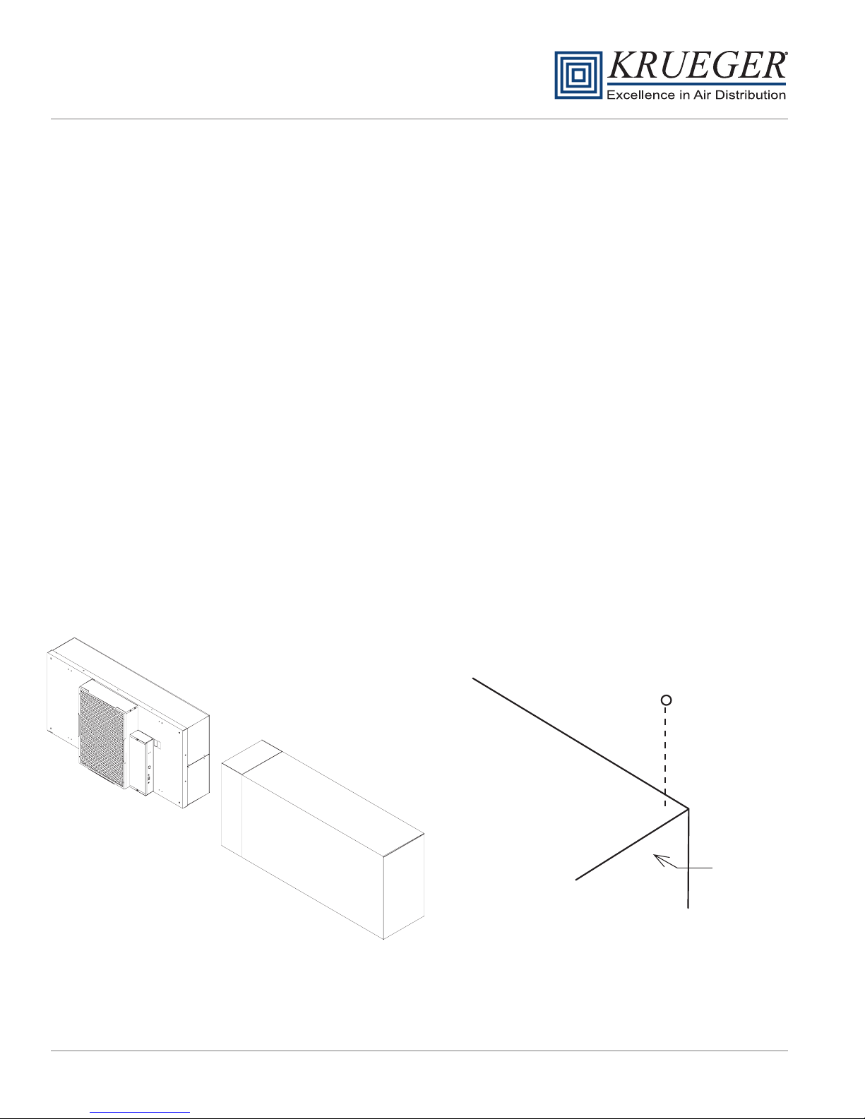
1. Carefully remove the unit from the shipping carton and inspect for any damage that may have occurred during
transportation. (See Figure 1)
Note: When ordering CRFF-ARS and CRFF-ARSM units, the HEPA filters may be shipped separately to be
installed into units after the fan box has been installed.
Recommendation: Review mode settings at this time as specified for installation (see page 7 for controls).
2. If using rigidly supported grid (usually 2” or wider), raise unit through ceiling and lower onto the gasketed grid. If
using a flexible grid (typically supported with wires) the unit must be secured to an overhead structure with
eyebolts, s-hooks and chain. Screw the four eyebolts into the nutserts on the lid assembly before lifting into an
overhead position (see Figure 2)
3. Have an electrician wire the unit to the appropriate voltage (115V, 220V, 277V AC), according to the wiring
diagram and all national and local electric codes. All units are equipped with a three position terminal block for
field connection. Verify correct single phase power, before energizing units.
4. Turn on the power using the two position rocker switch (ON/OFF) located on the electrical box. For the CRFF-
ARS and CRFF-ARSM units, let the unit fur for a few hours to purge off particulate (if filters are shipped loose)
that may adhere to the inside of the unit before installing the filters. Do not run fan at full speed as this may cause
overload condition.
Note: Your fan filter may have been shipped separate. Controls have been shipped separately.
EYEBOLT
FAN FILTER
UNIT
FIGURE 1 - UNBOXING FIGURE 2 - HANGAR SUPPORTS
Krueger | 1401 N Plano Rd | Richardson, TX 75081 | 972.680.9136 | [email protected] | www.krueger-hvac.com
Installation, Operation, & Maintenance for CRFF-E Series
Page: 5 of 26
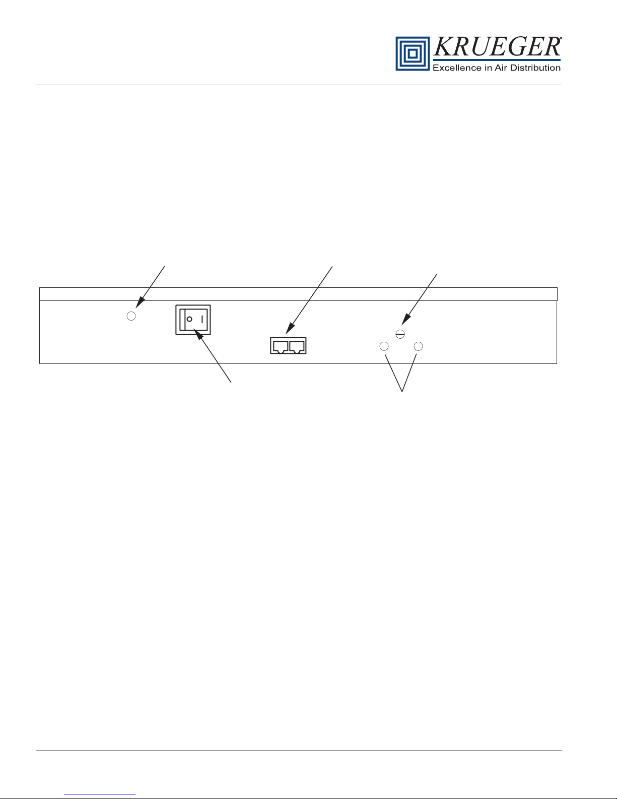
ON/OFF Switch - Speed/Airflow Adjustment
All CRFF-E series units are equipped with a two-position rocker switch (ON/OFF), which is located on the side of the
electrical box, on top of the unit. Unless otherwise specified, units are furnished with a Universal Control Card to
enable adjustment of airflow or set to preferred communication mode.
Note: The CAT5e/RJ45 network ports are non-directional (in or out). Be sure to examine your cabling to insure that
there is no cross-over wired cables.
CAT 5e
Network Cable Connection
(RJ45 Connector)
ON/OFF Switch RPM Test Probe Jack Comm.
Filter Indicator Light
Pressure Switch Adjuster Manual Speed Potentiometer
Filter Indicator Light Option
The pressure switch for the filter indicator light option is set at 0.60 in wc from the factory. The set point for the
pressure switch can be adjusted between 0.50 in wc and 3.00 in wc by turning the set screw, accessible for the front of
the control enclosure. Counterclockwise rotation will increase the set point differential for switching; clockwise rotation
will reduce the set point.
The process to adjust this for a specific application is detailed below:
1. Adjust fan to highest setting
2. Measure and note initial pressure differential between ceiling plenum and unit plenum (downstream of the fan
and upstream of the filter)
3. Restrict discharge airflow incrementally to increase differential pressure until measured value matches filter
loading requirements for the project
a. If no specific filter loading requirements are specified a general recommendation is to use twice the
pressure differential measured in step 2
4. With the unit discharge blocked, adjust the set point of the pressure switch
a. If the indicator light is illuminated, increase the set point of the pressure switch (CCW rotation) until the
light dims
b. If the indicator light is still dim, slowly decrease the set point of the pressure switch (CW rotation) until the
light illuminates
5. Remove obstruction(s) from the unit discharge
6. Adjust fan speed to operational set point
Krueger | 1401 N Plano Rd | Richardson, TX 75081 | 972.680.9136 | [email protected] | www.krueger-hvac.com
Installation, Operation, & Maintenance for CRFF-E Series
Page: 6 of 26
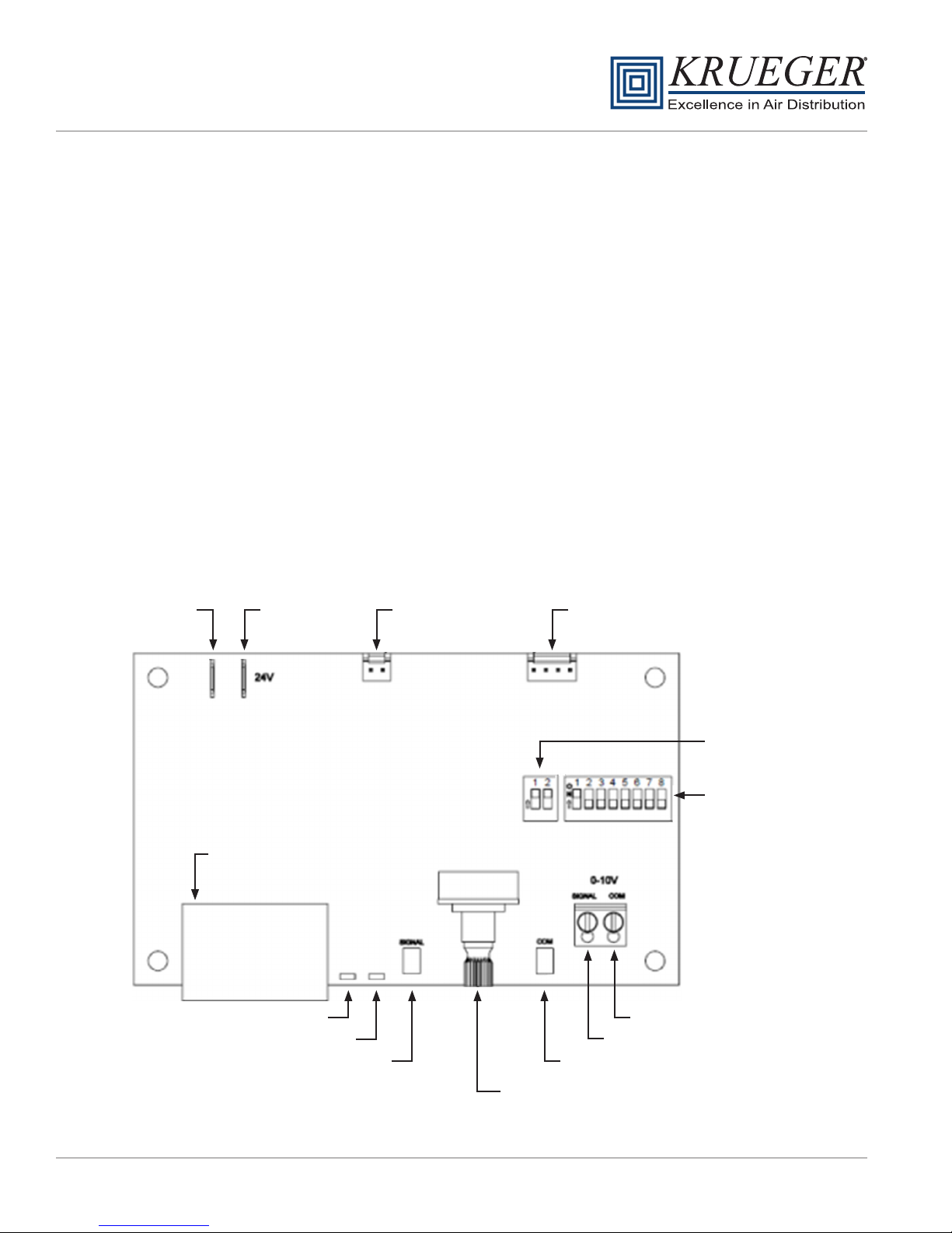
Universal Control Card Set Up (ENV1028)
CON4 UNIVERSAL CONTROL CARD - OVERVIEW
Krueger's ENV1028 Universal Control Card
provides MODBUS network and analog control
capabilities to a Krueger Fan Filter Unit equipped
with an electrically commutated motor. Three different
control modes provide installation versatility by allowing
the FFU to be controlled via MODBUS RTU network,
analog 0-10 VDC control signal, or by adjusting the
on-board potentiometer. The ENV1028 Universal
Control Card is fully compatible with all of Krueger’s
plug & play System Control Consoles using MODBUS
RTU. Additional details of the controls modes
are provided on page 7.
FEATURES
+Networkable Via MODBUS RTU
+ 0-10 VDC Analog Control
+ Manual Control Via Onboard Potentiometer
+ Simple Connections
- RJ45 For Networking Connection
- Screw Terminals For Analog Control
- Test Probe Jacks For DC mV Signal Output Of The Following:
- RPM
- Motor Control Set Point
+ LED Diagnostics
- Support for external LED (10mA) remote status notification via
2 Pin MTA connector
- On-board green LED for Board Status notification
- On-board red LED for Network Traffic
+ Powered from Network or Local Supply
COMMON INCOMING
POWER
24VAC
LED
CONNECTOR
CONTROL HARNESS
CONNECTOR
CONTROL
DIP SWITCH
ADDRESSING
DIP SWITCH
ANALOG INPUT “COM”
ANALOG INPUT “SIGNAL”
RPM TEST PROBE JACK “COM”RPM TEST PROBE JACK “SIGNAL”
GREEN LED FOR SYSTEM/RPM STATUS
RED LED FOR NET ACTIVITY
DUAL RJ-45 JACKS
FOR CAT5 CABLE
MANUAL SPEED POT
FIGURE 7: UNIVERSAL CARD OVERVIEW

Krueger | 1401 N Plano Rd | Richardson, TX 75081 | 972.680.9136 | [email protected] | www.krueger-hvac.com
Installation, Operation, & Maintenance for CRFF-E Series
Page: 7 of 26
Control Modes
The ENV1028 operates in one of three selectable modes.
The Mode is selected using the control DIP switch; MANUAL
control (on-board potentiometer), ANALOG control
(Remote 0-10 VDC), NETWORK control (MODBUS RTU).
The ENV1028 is shipped from the factory in NETWORK
control mode.
Manual Control Mode
In Manual control mode, the motor speed is set using the
onboard potentiometer. Onboard potentiometer rotation is
CW to increase the motor output.
Analog Control Mode
In ANALOG control mode, the motor output is set using an
external 0-10 VDC demand signal.
Network Control Mode
In NETWORK control mode, the motor output is set using
MODBUS Register 2. Motor output is specified as a value
from 0 to 100 representing a percentage of motor torque
output. Each ENV1028 in a MODBUS network must be
set to a unique address. The address value is set in
binary using the eight DIP switches of switch band (S2).
A maximum of 200 ENV1028 devices is recommended
per local area network (LAN).
NetworkkControl Mode (cont)
If a Krueger ACC Control Console is the MODBUS
master, then addresses should be assigned within the
address range supported by the Control Console.
Address zero should not be used as it is reserved for
global commands. Address switch settings are only
checked by the ENV1028 at power-up. Power must be
cycled (OFF/ON) before any changes take effect.
Registers relevant to this mode:
1
ON ADE02 21 3 4 5 6 7 8
O
N
2
1
ON ADE02 21 3 4 5 6 7 8
O
N
2
Manual Mode = 1 OFF 2 OFF
Analog Mode = 1 ON 2 OFF
Note: Network mode can be configured using either DIP switch setting shown
above. DIP switch pictorials are for reference and may be labeled differently by
the manufacturer.
1
ON ADE02 21 3 4 5 6 7 8
O
N
2
Network Mode = 1 OFF 2 ON
1
ON ADE02 21 3 4 5 6 7 8
O
N
2
Network Mode = 1 ON 2 ON
•Register 1 “Start/Stop” (R/W)
–To enable motor, write a value of 1; To disable
motor, write a value of 0
•Register 2 “Motor Set Speed” (R/W)
–Motor Target speed value. Values may be written
from 0 to 100
•Register 6 “RPM” (R)
–Motor RPM. Read from the motor
•Register 12 “Actual Motor Speed Instruction” (R)
–Speed control signal applied to the motor by the
ENV1028. (R/W) = Read/Write, (R) = Read Only
Installation, Operation, & Maintenance for CRFF-E Series
Page: 8 of 26
Krueger | 1401 N Plano Rd | Richardson, TX 75081 | 972.680.9136 | [email protected] | www.krueger-hvac.com
Control Modes (continued)
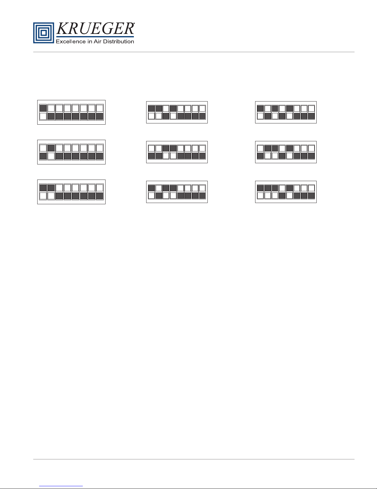
Example of binary S2 switch settings
5 61 2 3 4 87
ON DIP
1
1 2 3 4 5 6 7 8
ON
DIP
11
1 2 43 5 6 87
ON
DIP
21
31 2 4 5 6 7 8
ON DIP
2
1 2 3 4 5 6 7 8
ON
DIP
12
21 3 4 5 6 7 8
ON
DIP
22
1 2 3 4 5 6 7 8
ON DIP
3
1 2 3 4 5 6 7 8
ON
DIP
13
1 2 3 4 5 6 7 8
ON
DIP
23
Installation, Operation, & Maintenance for CRFF-E Series
Page: 9 of 26
Krueger | 1401 N Plano Rd | Richardson, TX 75081 | 972.680.9136 | [email protected] | www.krueger-hvac.com
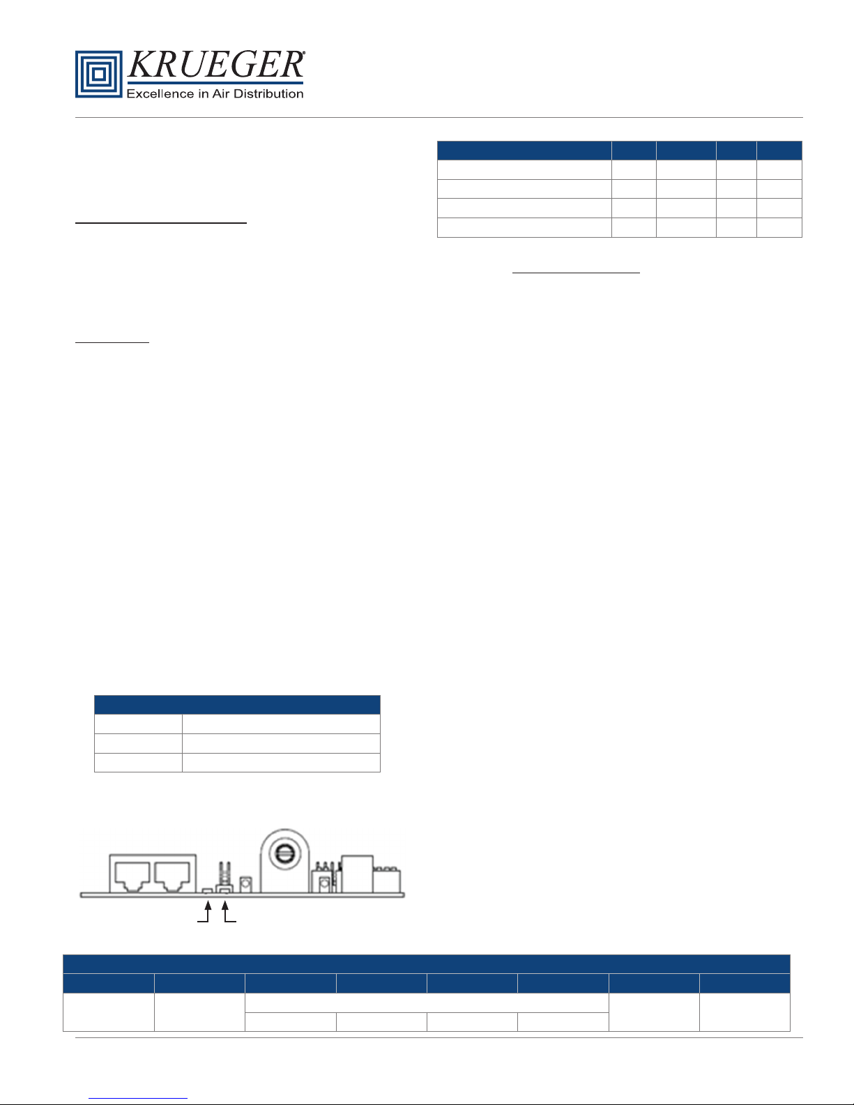
Electrical Specification
Control and Interface Signals
External Speed 0-10V Input
•Input impedance 20k0hms.
•MIN ON-to-OFF threshold: 190mV*
•MAX OFF-to-ON threshold: 240mV*
•ON (-215mV) to 9.89V linearly scales 1 to 99% speed.
•9.89V or more deadbands to 100% speed.
External LED Output
•10mA regulated.
•LED forward voltages up to 5V.
RPM Signal
•Signal Value: mVDC = RPM
•Ex: 900mV = 900RPM
•RPM Output Range: - 0, 5 to 2000 RPM (0, 5mV to 2000 mV DC)
•RPM Output Resolution: 5RPM (zero, 400 steps from 5 to 2000 RPM inclusive)
Specificatio Min Typical Max Units
Input Voltage 22 24 42 VAC
Supply Frequency 50 50 / 60 60 Hz
Input Power Consumption n/a n/a 0.5 VA
Ambient Operating Temperature 0 25 50 C
RJ45 Network Cable Connections
12345678
Bus Power
Pass Through 0V (GND) RS-485 0V (GND) Bus Power
Pass Through
+ NC NC -
Net LED Status Definitio
Green LED OFF Power lost or no communications.
LED Flickering Network data traffic in progress
Green LED ON A/B network cables are swapped.
RED NETWORK LED GREEN STATUS LED
FIGURE 9: LED LIGHT LOCATIONS
Test Probe Jack Points
The test probe jacks may be used to measure the motor
rpm or the PWM signal that is being output to the motor.
•In Manual or Analog Control Mode with an Address
setting of 1 or greater, the test probe jacks output
0-2000 mVDC representing motor RPM. By changing
the address DIP switches to 0, the test probe jacks will
output 0-1000 mVDC representing 0-100% demand
signal to the motor. The address may be changed
without interrupting power to the control card.
•In Network Control Mode, 0-2000 mVDC always
represents RPM.
LED Indicators
•Onboard Status LED:
The Onboard Status LED is software controlled
by the unit microcontroller. The Status LED is solid
ON when RPM reported by the motor is greater than
zero and OFF when RPM reported by the motor is
zero.
•External Status LED:
Support for an external Status LED (10mA current-
controlled driver), via a 2-pin MTA connector, for
remote system status notification. The external Status
LED operates in the same manner as the Onboard
Status LED.
•Onboard Net LED:
The Onboard Net LED is driven directly by the receive
data signal. The NET LED shows all network traffic on
a 2-wire network. The NET LED is intended to
confirm low-level network connectivity,
independent of microcontroller or firmware
functionality. If A/B network wires are swapped, the
NET LED will be normally on, providing quick
diagnostics of this common condition.
Installation, Operation, & Maintenance for CRFF-E Series
Page: 10 of 26
Krueger | 1401 N Plano Rd | Richardson, TX 75081 | 972.680.9136 | [email protected] | www.krueger-hvac.com
Communication Specification
Overview
• MODBUS RTU protocol over RS485 (serial).
• 9600 baud rate, word length is 8, parity is none(n), stop bits=1.
• 255 unique address values selectable by DIP switch settings. (Recommended network node capacity 200 nodes.)
• Slew rate limited transceivers for improved network performance.
• Do not use crossover cables. This may damage the control card or render it non-operational.
To reset non-volatile registers to factory default values, write 170 (AA hex) to Register 14, then cycle power.
Note: Register 24 may be read in network mode to determine the value of 0-10VDC signal that may be
connected. For example, a pressure transducer may be conected to indicate unit static pressure
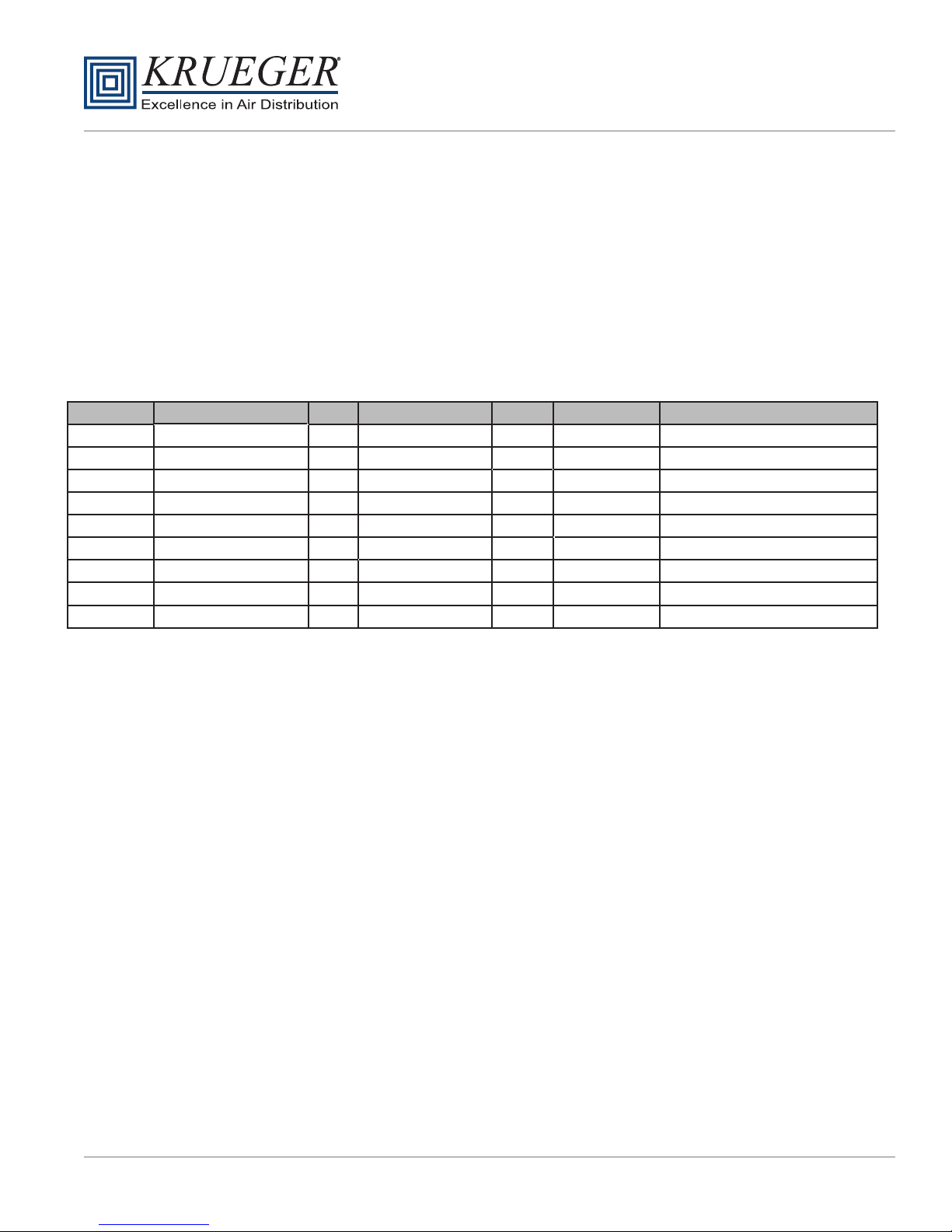
MODBUS REGISTER SUMMARY TABLE
1
2
6
9
10
12
14
1
1
RUN/STOP
DEMAND
SPEED
STATUS
DEFAULT SPEED
CURRENT SPEED
DEFAULT RUN/STOP
RW
RW
RW
RW
R
R
R
0-100
0-100
0-100
0,1
0,1
0,5-2000
see detail
%
RPM
50
-
-
RAM
RAM
LIVE
LIVE
LIVE
EEPROM
EEPROM
power up from REG 14
power up from REG 10
applies to network only
applies in network mode only
Register Name R/W Values & Defaults Units Origin Comments
24
70-1000 LIVE
-
ANA1 Onboard Pot 0-1000=0-100%
0-1000 LIVE
-
ANA2 0-10V input 0-1000=0-10VDC
R
R
This manual suits for next models
2
Table of contents
Popular Water Filtration System manuals by other brands

Wisy
Wisy LineAir 100 Installation and operating instructions

Schaffner
Schaffner Ecosine FN3446 Series User and installation manual

Pentair
Pentair FLECK 4600 SXT Installer manual

H2O International
H2O International H20-500 product manual

Renkforce
Renkforce 2306241 operating instructions

Neo-Pure
Neo-Pure TL3-A502 manual


