Apollo Entertainment KiwiSat Guide

INSTALLATION AND USE MANUAL
GB

TABLE OF CONTENTS
1 INTRODUCTION
1.1 Symbols used ..........................................................................................................Page 3
1.2 Proper use ................................................................................................................ Page 3
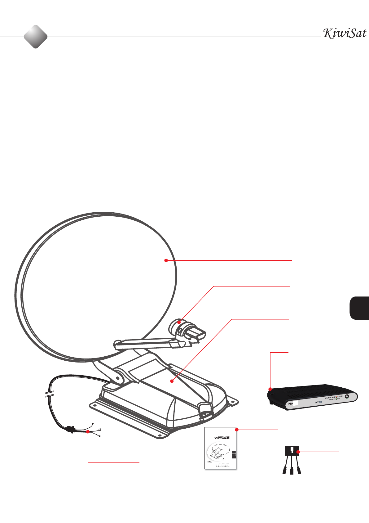
1.3 Description ............................................................................................................. Page 4
1.4 Components............................................................................................................ Page 5
1.5 Technical specifcations.......................................................................................Page 6
2 INSTALLATION
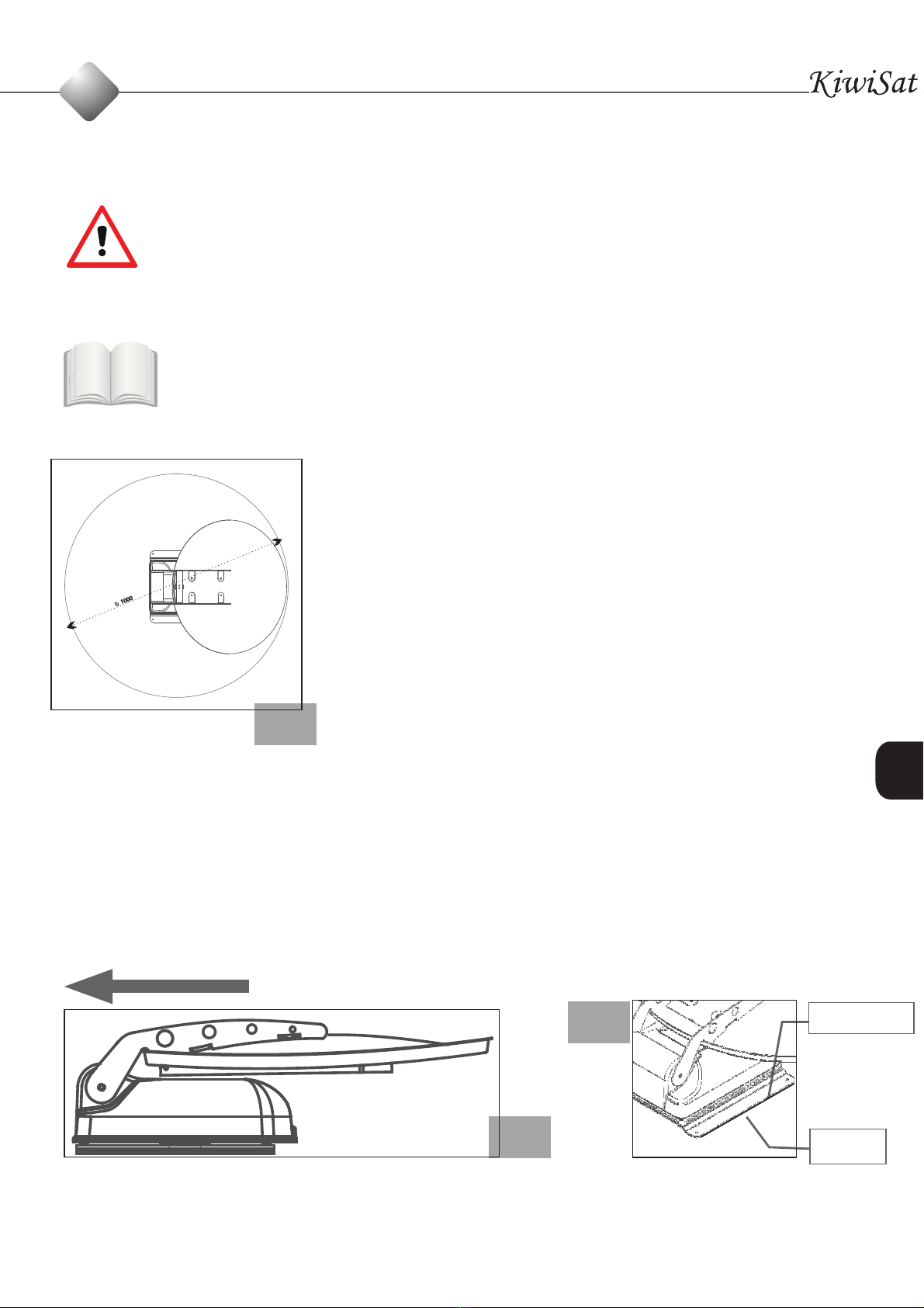
2.1 Assembly instructions of the external unit ..................................................Page 7
2.2 Assembly instructions of the cable run box ...............................................Page 8
2.4 Electrical connections ..........................................................................................Page 10
3 GENERAL SAFETY REGULATIONS
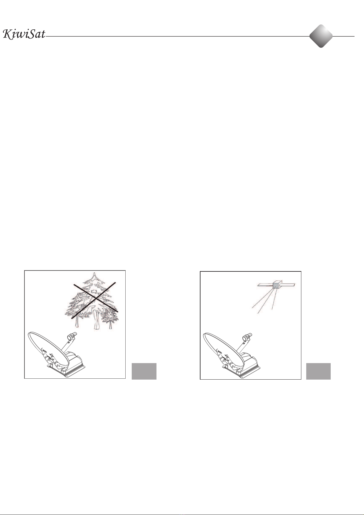
3.1 Working area .......................................................................................................... Page 11
3.2 Safety and electric supply ..................................................................................Page 11
3.3 People’s safety ........................................................................................................Page 11
3.4 Safety during assembly .......................................................................................Page 13
4 USE
4.1 Destination of use ................................................................................................Page 13
4.3
Satellite search and selection ...........................................................................Page 15
5 DISPOSAL ..........................................................................................................................Page 16
6 INFORMATION
6.1 Service....................................................................................................................... Page 16
6.2 Warranty ................................................................................................................... Page 17
6.3 Manufacturer’s declaration of conformity ....................................................Page 18
6.4 Troubleshooting.................................................................................................... Page 19
6.5 Service centers .......................................................................................................Page 20
0
2
..................................................
2.3 Assembly instructions of the control Box
...............................................
Page 9
4.2 Description of the 2P control panel
...................................................................................
Page 14

INTRODUCTION
Congratulations on buying this satellite dish with automatic tracking. This
is a technologically advanced and high quality product for satellite TV recep-
tion in vehicles.
Before installing and operating the, satellite system examine carefully the functions of the
device and its proper use.
Carefully read this use manual and always keep it close to the device for quick and easy
reference. If the device is transferred to a third party, do not forget to pass on all the neces -
sary documents.
1.1 Description of the symbols used
Read the instructions
manual Important warning
Keep to the safety warnings
Dispose of the device in an
environmentally friendly
manner
Operations to be per-
formed exclusively by
authorised and trained
personnel
See the picture concerning
the letter shown
A
1.2 Proper use
For correct use of your automatic satellite dish, check the following:
1.2.1 Make sure that no trees, walls, buildings or other objects that may compromise the
reception of the TV satellite signal are close to the satellite dish before opening it. (see
pictures 1A and 1B )
1.2.2. Before switching the system on, make sure that there areno obstacles
that might hinder the opening and rotation of the satellite dish (tree branches,
balconies, canopies, etc)
GB
1
3

1.2.3 The satellite dish has been designed and tested to resist a wind speed of 100 km/h.
However, in the case of very strong wind, we suggest you keep the satellite dish closed
because its wide surface may cause damage stress to the roof of your vehicle.
1.2.4 The battery voltage must always be sufficient; if the supply voltage is lower than 10V,
the electronic safety circuit will prevent the satellite dish from being lifted.
1.2.5 The battery voltage must always be sufficient; if the supply voltage is lower than 10V,
the electronic safety circuit will prevent the satellite dish from being lifted.
1.2.6 The satellite dish must be used only if the external temperature is between -15°C
and + 45°C. Using the satellite dish outside these values may damage the satellite dish or
cause malfunctions.
1.2.7 After using the satellite dish and before moving of, make sure that the satellite dish
is closed. In any case, do not move until the audible signal that indicates that the dish is
parked turns of.
NO OK
1.3 Description
Your VM Sat satellite dish uses a totally automatic satellite tracking system.
This system can track satellites that give a signal modulated in QPSK, according to the
DVB-SI EN 300 468 Standard, and can hence:
• search the selected satellite
• park the satellite dish
1A 1B
1
4

1.4 Components
1 Motor-driven external unit
2 Offset satellite dish
3 Universal LNB
4 Wiring
5 Assembly and use manual
6 Control box for external unit
7 Box power connector
GB
1
3
1
2
6
7
5
4
5

1.5 Technical specifcations
• Satellite dish offset
• Search system fully automatic NID recognition according to
the DVB-SI EN 300 468 specifications
• Settable satellites only Factory Depending on the model for the country:
• Power supply 12V DC -20 + 30%
• Absorbed current Max 3 Ampere
• Current absorbed in stand-by ≤5mA
• Weight ≤12kg
• Protection fuse 3A
• Size (when closed) height: 195 mm
Width: 610mm
Length: 650mm
INSTALLATION
Only specialised personnel should install the satellite dish. Incorrect installation
may damage the system.
Before installation, open the carton packaging and make sure that the satellite dish
is in good condition. Make sure that all parts described in the instruction manual are
present. (VM Sat does not accept any claims for damage caused by transport
or missing material after the satellite dish has been installed).
1
ASTRA 19 - HOTBIRD 13 ( Germany - Italy )
ASTRA 19 - ATLANTIC BIRD ( France )
ASTRA 19 - ASTRA 23.5 ( Netherlands)
ASTRA 19 - ASTRA 28 ( England )
6
2
OPTUS D1-T1 ( New Zeland )
OPTUS D3-T1 ( Australia )

2.1 Assembly instructions of the external unit
CAUTION! Read carefully the safety standards concerning installation before in -
stalling the device. The non-observance of these instructions may lead to dam -
age or serious injuries.
2.1.1 On the roof of the vehicle, find a sufficiently large area of roof (preferably
at the sides of the roof) that allows for the positioning of the satellite dish (see
picture 2 )
2.1.2 Clean carefully the area of the roof selected for the in-
stallation of the external unit (remove oil, grease and
dust). Carefully clean the lower part of the fastening
plate in order to remove any trace of dust and grease.
2.1.3 With a silicon gun apply a homogenous layer of struc-
tural polyurethane adhesive at ambient temperature
in the lower part of the fastening plate (dekasyl MS-2
OR MS-5 glue is recommended; keep to the instruc-
tions for application).
2.1.4 Position the external unit on the previously
cleaned roof area. Push strongly on it in order to ensure
a good distribution and adhesion of the glue.
CAUTION!!! When assembling the external unit, ensure that the bottom of the dish when
closed is facing the direction of travel (see picture 3)
To complete the installation of the external unit, apply a layer of adhesive around the fas -
tening plate in order to make it totally waterproof (see picture 4)
2
DIRECTION OF TRAVEL
Note: leave the adhesive to set for 24 hours before moving the vehicle
GLUE
ROOF
3
4
2
GB
7
2
1000

2.2 Assembly instructions of the cable run box
2.2.1 For easy and quick installation of the satellite dish, find a position on the roof
where the supply and control box will be installed (see 2.3.1) .
2.2.2 With a 20 diameter hole cutter make a hole for the passage of the cables inside
the vehicle’s cabin.
2.2.3 Clean and remove any grease from the surface around the hole. Take the cable
box and make a hole in it so the M25 cable (which includes the sat cable and the internal
connection cable) can pass through.
2.2.4 Run the cables inside, through the hole previously made in the roof and fix the
cable firmly to the cable box with the bolt (supplied in the kit).
2.2.5 Apply a generous layer of polyurethane adhesive on the base of the box (use the
same type as that used for the fastening of the external unit). Position the box on the roof
close to the hole and press in order to ensure a good distribution and adhesion of the glue.
Run the cables securely along the roof (insert them into a cable channel in order to protect
them from UV rays) and bring the excess cables into the camper.
2.2.6 The cables must be fastened to the roof in order to prevent them from moving or
being caught by objects such as branches.
The external assembly of the satellite dish is now complete.
2
8

2.3.1 Find a place inside the vehicle that is easily accessible to the user, preferably near
the TV or inside a cupboard.
2.3.2 Position and fasten the wall box inside this accessible and ventilated area so that
any service operations can be performed easily and quickly (see picture 5).
CAUTION! The ventilation of the device is important because it avoids overheating
of the components.
5
It is advisable to fasten the box
onto the wall with two screws. It
should be fastened vertically and
positioned either to the right or
left of the TV.
2.3 Assembly instructions of the control box
2
GB
9

2.4 Electrical connections
2.4.1 Connect the black cable from the external unit to its terminals on the internal con -
trol box (see drawing 7).
2.4.2 Connect the black coaxial cable from the satellite dish LNB to the F connector of
the control box.
Note: in satellite dishes with dual output, the second black coaxial cable from the satellite
dish must be directly connected to the second receiver (see drawing 7.1).
2.4.3 Insert the power connector supplied with the system into the special connector
on the control box.
2.4.4 Connect the black cable of the power connector to the negative pole of the do-
mestic battery and the red cable to the positive pole of the domestic battery.
2.4.5 Connect the green cable of the power connector to the special D+ position on
the vehicle dashboard. This enables automatic closing of the satellite dish in case it is left
in the up position.
2
In many cases the connection is on pin 15 of the general terminal board and in any case
it corresponds to an active and positive voltage of +12 VDC generated when the vehicle
ignition key is rotated.
This connection prevents the operation of the satellite dish when the vehicle is moving
or the ignition key is turned for ignition.
10

DECODER 2
GREEN CABLE
GREEN CABLE
BLACK CABLE
BLACK CABLE
RED CABLE
RED CABLE
WIRING DIAGRAM, ONE-OUTPUT VERSION
NOTE: THE DECODER AND ITS CABLE ARE NOT INCLUDED
WIRING DIAGRAM, TWO-OUTPUT VERSIONS
NOTE: THE DECODER AND ITS CABLE ARE NOT INCLUDED
TO THE IGNITION KEY OF THE
VEHICLE (+ 12 V CURRENT)
TO THE IGNITION KEY OF THE
VEHICLE (+ 12 V CURRENT)
7
7.1
DECODER
DECODER 1
7.1
GB
2
11

GENERAL SAFETY REGULATIONS
CAUTION ! Read all the instructions.
The improper or non observance of these instructions may result in serious dam -
age and injuries.
KEEP THESE INSTRUCTIONS
3.1 Working area
Before switching the system on, always make sure that the working area is free
from obstacles (tree branches, protruding balconies etc.).
RISK OF DAMAGE TO SATELLITE DISH AND VEHICLE
3.2 Safety and electric supply
The device must be exclusively powered with 12 V, supplied directly from the service bat-
tery using cables with a minimum section of 2.5 mm.
If a 12V electric power supply is used instead of the battery, make sure that it is stabilised
and able to deliver 3 Amps continuously and 10 Amps for short periods.
Do not use a poor quality battery charger that is not stabilised.
3.3 People’s safety
Before enabling the opening of the satellite dish, make sure that nobody is on
the vehicle roof. If someone is on the roof of the camper, he/she could be hit by
the satellite dish when it is opened or closed.
RISK OF SERIOUS INJURY
3
12

3.4 Safety during assembly
For the assembly operations that imply the risk of fall, the necessary safety pre-
cautions must be adopted: for instance, a work bridge to be used when op-
erating on the vehicle roof. Make sure that the roof of the vehicle has sufficient carrying
capacity for the assembly operations.
Moreover, during assembly make sure that :
- The device is disconnected from the electric mains
- The person in charge of the assembly does not sufer from vertigo
- The person in charge of the assembly wears non-slip and accident-prevention
shoes.
- Nobody is under the satellite dish during assembly.
- The lifting apparatus is non-slip and dry.
- The bridge and ladder are sufficiently stable and robust
4
4.1 Destination of use
The satellite dish is manufactured for the reception of digital TV and radio signals from a
satellite only when the vehicle is stationary. The reception unit allows for the reception of
satellite TV and radio signals whose frequency is included between 10.7 GHz. and 12.75
Ghz. Any different use renders the warranty void.
Caution: VM Sat does not accept any liability for damage caused by:
- Wrong use that does not comply with the intended use of the device
- Repairs not performed by authorised service centres
- Tampering with any mechanical components
- Use of non-original spare parts and fittings
- Non-observance of the instructions in this manual
IN THE ABOVE-MENTIONED CASES THE WARRANTY IS VOID
GB
3
13
4

4.2. Description of the 2P control panel
Switching on
To switch on the system press the on/of (3) button on the control panel. When this but -
ton is pressed the red and green LED will simultaneously be switched on to check that
the LEDS are working correctly. After a few seconds the LED to the selected sat
start to flash, to show that the system is searching for the satellite. Once the satellite
has been found and confirmed the LED of selected sat will stop flashing and remain
fixed The LED will then begin to flash very quickly when the signal is recognized
and will go back to fixed mode as soon as the satellite is acknowledged.
Please note that for any warning signals you must read paragraph 6.4.1
ON/OFF BUTTON (3)
USB PLUG FOR
REPROGRAMMING
4
SATELLITE WORKING POWER / ALARM
14

4.3 Satellite search and selection.
The system starts searching for the previously selected satellite as soon as it is
switched on.
If the satellite shown is not the one you want, press fasted button 3 ( ON/OFF )
of the control panel and :
The system will automatically search for the selected satellite and will store its
position in order to facilitate and speed up subsequent searches.
If the satellite is not able to find the satellite after performing a full scan, the sys-
tem will set the satellite dish to its parked position.
4
GB
15
TURQUIE:
HOT BIRD 13 E (2=22°)
ASTRA 19 E (2=15)°
ASTRA 28 E (2=5°)
8 8.1
0
2
MAROC:
HOT BIRD 13 E (1=27°)
ASTRA 19 E (1=34)°
ASTRA 28 E (1=41°)
01
PORTUGAL:
HOT BIRD 13 E (1=25°)
ASTRA 19 E (1=28)°
ASTRA 28 E (1=37°)

In compliance with article 13 of Law Decree n. 151 of 25th July 2005 “implementation
of the 2002/95/EC, 2002/96/EC and 2003/108/EC Directives concerning the reduction
of hazardous materials in electric and electronic devices and of waste disposal”
This symbol means that this device must be disposed of separately from other
waste and not in household waste after its use.
The user must dispose of this device in the special collection centres for electric
and electronic waste, as regulated by the local legislation in force.
The proper selective waste collection, followed by recycling, treatment and eco-compati -
ble disposal of the device, has a positive impact on the environment and health because it
facilitates the re-use and recycling of the materials composing the device.
The illegal disposal of the product by the user implies the administrative sanctions pro-
vided for by the regulations in force.
INFORMATION
DISPOSAL
6.1 Service
CAUTION ! Only qualifIed and authorized personnel can repair the device (see
paragraph 5.5 on the service centres). This guarantees that the device is used in
conditions of safety, without running the risk of voiding the warranty and that only
original spare parts are used.
16
6
5

6.2 Warranty
6.2.1 The device has a warranty of 2 years from the date of purchase for all its
mechanical parts. For the electronic parts VM Sat warrants that the device
has been manufactured and tested carefully and is therefore free from defects before its
delivery.
6.2.2 Keep the receipt or invoice, which must be shown as a purchase proof for any
service operations under warranty (otherwise the warranty is void).
6.2.3 VM Sat will repair any defects found on this device free of charge in a rea -
sonable time after receiving the device. The necessary costs for this purpose, especially the
work and material costs, will be totally charged to us, while the costs and risks concerning
the transport of the device to the authorised centre will be charged to you.
6.2.4 The operations under warranty do not imply an extension or renewal of the war-
ranty period of the device. The replaced parts become automatically our property.
6.2.5 For any warranty operations we kindly ask you to deliver your device to our au-
thorised service centre. Make sure that the packaging is in perfect conditions for a safe
transport (original packaging). A brief description of the failure must be included and in -
serted in the pack, together with your full address. Moreover, as a proof of warranty right,
do not forget to put your original document of purchase (receipt or invoice) in the pack.
6.2.6 WAIVERS
The warranty does not cover those defects that:
- occur following improper, negligent or careless use or storage of the device;
- are caused by wrong installation, maintenance or repair performed by non authorised -
personnel or by damage caused by transport;
- are not referable to manufacturing defects;
- are caused by the use of non original spare parts and accessories;
- have been caused by lightning, wrong supply voltage or other force majeure events, not
ascribable to the Manufacturer.
GB
17
6

6.3 Manufacturer’s declaration of conformity
Declare, under their own responsibility, that the following product:
AUTOMATIC SATELLITE DISH, Type Kiwisat
Complies with the following standards :
: 55022, EN 55024
: 12100-1,EN12100-2,EN294,EN349
: EN60529
: 965/56 EEC
Electro-magnetic compatibility
Machine safety
IP level
529 vibration
Acquaviva - RSM il 01.06.2017
The owner
Marco Santoli
CE DECLARATION OF
CONFORMITY
18
MA-VE International s.r.l
Strada Genghe Di Atto, 105
47892 - Acquaviva RSM
6

PROBLEMS CAUSES SOLUTIONS
The satellite dish cannot be
opened -No power supply to the satellite
dish
-An obstacle is on the satellite dish
-The vehicle is moving or engine
is on
-Loose or broken connection
-Check the power supply & fuse
-Switch the control panel on
- Remove the obstacle
- Stop the vehicle and turn of
- Check the connections
Error: satellite not found - Obstacles in front of the satellite
dish (trees, metal walls, buildings,
etc.) prevent the reception of the
signal.
- The connection from the box to
the LNB is loose
- You are outside or at the extreme
limits of the satellite footprint
- Move the vehicle away from
anything that prevents satel-
lite reception and make sure
that the South is free from ob-
stacles
- tighten the connectors and try
again
- Make sure that you have fol-
lowed the instructions in para-
graph 4.7; otherwise wait until
you arrive in a more central
area
Error: rotation maximum
stress - there are obstacles in the area of
action of the satellite dish (trees,
ice or snow)
- remove the obstacles that pre-
vent rotation
Error: elevation maximum
stress - there are obstacles in the area of
action of the satellite dish (trees,
ice or snow)
- Remove the obstacles which
are causing the obstruction .
Rotation error - the rotation motor does not work - check the connections of the
grey cable to the box from the
satellite dish to the external
unit position
Elevation error - the elevation motor does not
work - check the connections of the
grey cable to the box from the
satellite dish to the external
unit position
Error: insufficient
power supply - the battery is too low and cannot
ensure the correct operation of
the system
- charge the battery
Error: unstable
power supply - faulty battery or presence of non
stabilised power supply Turn of any current generators
or have the battery checked
The satellite dish
loses the signal - slow connections
- strong storm or wind
- check and tighten the F con-
nections of the box, satellite
dish and decoder
- wait until the storm or wind
cease
RF cable error broken or disconnected satellite
cable - check the connection
- check the supply voltage
- check the LNB
6.4 Troubleshooting
GB
19
6

SIGNAL DESCRIPTIONS PROBLEMS
1 flash with 1 beep - vertical rotation error
2 Flashes with 2 beeps - horizontal rotation error
3 Flashes with 3 beeps - maximum effort error
4 Flashes with 4 beeps - satellite not found error
5 Flashes with 5 beeps - battery
6 Flashes with 6 beeps - check RF cable
7 Flashes with 7 beeps - violation error range vertical
8 Flashes with 8 beeps - violation error range horizontal
9 Flashes with 9 beeps - key camper ON
10 Flashes with 10 beeps - power unstable error
This type of control panel manages errors through
light impulses and acoustic warning signal sequences. When a functional error occurs the
red led turns on in a fixed mode. To find out what kind of error has occurred you only have
to press the ON/OFF button. A series of fashing and acoustic signals will indicate what
kind of error is underway. Please see the below table.
6.4.1 PROBLEMS AND SOLUTIONS CONTROL PANEL 2 P
WARNING !To clear your antenna from any errors, push the ON/OFF button for 5
seconds until the green LED begins to flash.
If the error is correctable the antenna will begin to function normally; if not then
you must contact your nearest service center.
DISPOSAL
20
6
This manual suits for next models
1
Table of contents
Popular Satellite TV System manuals by other brands

Winegard
Winegard RM-4610 owner's manual

SLX
SLX 27868HS user guide

General Dynamics
General Dynamics 1.2M Ku-BAND RxSERIES 1132 Assembly manual

KVH Industries
KVH Industries TracPhone/Iridium Bundle quick start guide

KVH Industries
KVH Industries TracVision HD7 installation guide

KVH Industries
KVH Industries TracVision M7 installation guide

Ten-Haaft
Ten-Haaft Oyster Vision II quick start guide

KVH Industries
KVH Industries TracVision G8 owner's manual

Dish Network
Dish Network TV1 Quick reference guide

Uniden
Uniden UST4400SUPER operating guide

KVH Industries
KVH Industries TracVision Cruiser user guide

KVH Industries
KVH Industries TracVision M7 installation guide