APOLLO VIEW IOU User manual

IOU
MANUAL V1.1

2
LIMITED WARRANTY ..................................................................................................................................3
INTRODUCTION .........................................................................................................................................4
WHAT IS IT?..........................................................................................................................................................4
SPECIFICATION ....................................................................................................................................................4
INSTALLATION IOU.....................................................................................................................................5
POWER.................................................................................................................................................................5
IOU FUNCTIONALITY ..................................................................................................................................6
KEY.......................................................................................................................................................................6
INPUT...................................................................................................................................................................7
CONTROLS ...........................................................................................................................................................7
SWITCHES ............................................................................................................................................................7
OUTPUTS .............................................................................................................................................................7
PATCH IDEAS .............................................................................................................................................8

3
Limited Warranty
Apollo View Modular Ltd warrants this product to be free from defects in materials or
construction for a period of one year from the date of purchase (proof of purchase/invoice
required).
This warranty does not cover any damage caused by misuse of the product, or any
unauthorised modification of the product.
Apollo View Modular Ltd reserves the right to determine what qualifies as misuse at their
discretion. Examples of misuse include, but are not limited to:
1. Exposure to extreme heat or moisture
2. Malfunction resulting from wrong power supply voltages, backwards or reversed
Eurorack bus board cable
3. Issues related to third party products
4. Any condition resulting from incorrect or inadequate maintenance or care.
5. Damage resulting from misuse, abuse, negligence, accidents or shipping damage.
6. Dissatisfaction due to buyer's remorse
7. Normal wear and tear
8. Damage to the product caused by excessive physical force or abuse of the product,
removing knobs, changing faceplates
This warranty does not cover any other causes determined by Apollo View Modular Ltd to
be the fault of the user, and standard service rates will apply.
Apollo View Modular Ltd agrees, at its option during the warranty period, to repair any
defect in material or quality or to furnish a repaired or refurbished product of equal value in
exchange without charge (except for a fee for shipping, handling, packing, return postage,
and insurance which will be incurred by the customer). Such repair or replacement is subject
to verification of the defect or malfunction and proof of purchase as confirmed by showing
the model number on the original dated sales receipt.
Apollo View Modular Ltd implies and accepts no responsibility for harm to persons or
apparatus caused through the operation of this product.
Please contact info@apolloviewmodular.com with any questions, requests for a return to
the manufacturer, or any needs & comments.
https://www.apolloviewmodular.com/

4
Introduction
WHAT IS IT?
Invert Offset Utility –Precision Control of CV and Audio in a Slimline 2HP Design
IOU is a highly versatile DC-coupled signal processor, perfect for CV and audio inputs.
Standard and inverted polarity outputs are complemented by a selectable 1x or 2x output
gain switch, designed to boost low-level signals or to increase the DC Offset control range
up to +10V on the 2x setting. At the core of IOU's interface are an attenuverter for signal
scaling and inversion, and a unipolar DC Offset Slider with an LED indicator for visual
feedback. These controls offer precise signal manipulation, enabling amplification,
attenuation, inversion, and offset. Additionally, the module includes a unique DivKid-
requested feature, introducing an innovative layer of versatility for the user.
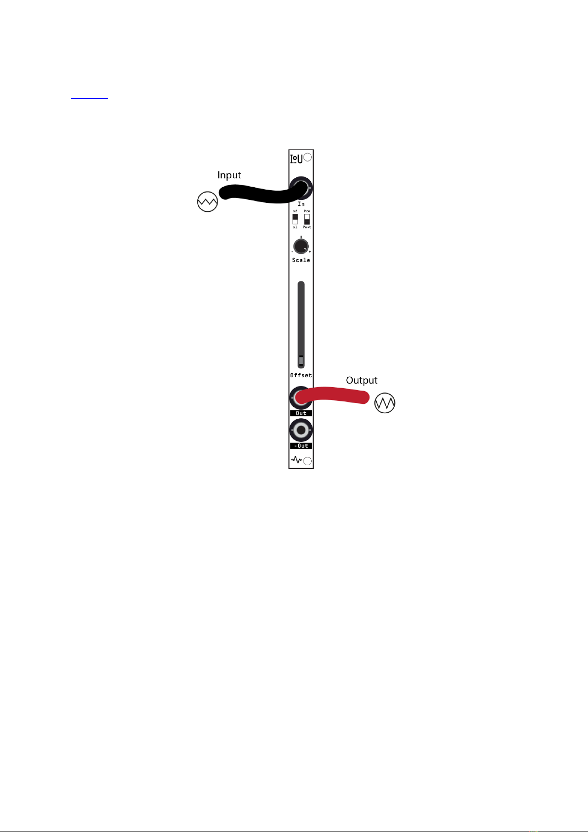
The two Outputs from the module are symmetrical, providing equal and opposite (inverted)
signals. This dual-output setup is useful for techniques like sidechain compression (ducking)
and crossfading when used with VCAs (see later examples).
The attenuverter is a key component of the IOU, providing control over signal amplitude
and polarity. The functionality of this feature is expanded by the DivKid-suggested Pre/Post
switch, allowing users to choose the application of the DC offset relative to the
attenuverter's processing. 'Post' mode offers direct control with up to +10V of offset, while
'Pre' mode enables the offset range to be limited and/or inverted by the attenuverter. The
synergy between the attenuverter and the DC offset, particularly the signal routing flexibility
afforded by the Pre/Post switch, is integral to the IOU's design, offering users extensive
creative control.
IOU excels at CV signal scaling, inversion, and offsetting and accurately handles audio signal
processing for attenuation, gain, inversion, and clipping. These features allow for meticulous
control over other modules, enhancing any Eurorack setup with the potential for more
elaborate and inventive patching.
IOU is an indispensable tool engineered to expand your modular synthesis system's
functional range and versatility.
SPECIFICATION
•2HP
•30mm depth
•Reverse polarity protected
•+12V 15mA
•-12V 5mA

5
Installation IOU
POWER
Before installing IOU, ensure your Eurorack system is powered off. IOU is supplied with a 10-
pin to 16-pin power cable. Carefully align the 10-pin end with the 1x5 pin header on the
module's rear, centering it to prevent any overhang that could cause issues when installing
it into the case. The red stripe on the cable indicates -12V and must align with the !RED!
marking on IOU for proper polarity.
Next, find a 2 HP slot in your Eurorack case for IOU. Connect the other end of the power
cable to your Eurorack power supply, again ensuring the red stripe aligns with the -12V rail.
With the power connection established, mount the module into your case using appropriate
screws and power on your Eurorack system.
The module has reverse protection diodes, which will divert the reverse current to ground in
case of incorrect installation.

6
IOU Functionality
KEY
1. Input
2. 1x / 2x Gain Select Switch
3. Pre / Post Switch
4. Scale –Attenuverter
5. Offset –Unipolar DC offset Slider
6. Standard Output
7. Inverted Polarity Output

7
INPUT
In - DC-coupled input accepts both audio signals and control voltages (CV), ensuring
versatile interfacing with your Eurorack system.
CONTROLS
Scale - This attenuverting knob allows you to adjust the amplitude of the incoming signal
precisely. At the 12 o'clock position, the signal is brought to zero Gain, while turning
clockwise (CW) increases the signal up to unity gain, and anti-clockwise (ACW) inverts the
polarity.
Offset - Provides manual control over the DC offset of your signal, allowing for the addition
or subtraction of a static voltage. The Slider is equipped with an LED indicator for visual
feedback, ensuring precise adjustments.
SWITCHES
1x / 2x Gain –This switch lets you choose between unity gain (1x) and an amplified signal at
2x Gain (+6dB), accommodating Eurorack's diverse modulation voltage levels. It's designed
for seamless integration with various modules while also enabling creative uses like driving
signals into other modules for enhanced saturation and distortion effects. Additionally, the
2x setting extends the DC offset Slider's range, allowing for adjustments from 0 to 10V,
offering even more modulation possibilities.
PRE / POST –A feature requested by DivKid, this switch offers creative flexibility by allowing
you to choose whether the DC offset is applied before or after the attenuverter's action,
offering greater control over the final output signal.
OUTPUTS
IOU is equipped with dual-polarity outputs, providing both non-inverted and inverted
versions of the processed signal. The non-inverted Out replicates the signal's post-
processing state, while the inverted -Out provides an exact inverse, allowing for creative
differential modulation techniques and exploration of phase cancellation effects in your
patches.
Precision control over your Audio and CV —IOU nothing less…

8
PATCH IDEAS
NOTE: We worked with DivKid not only for his Pre/Post switch idea but also to
provide a comprehensive video on using utilities to improve your patching.
While you don't need to watch the video for the following patch examples,
the video will support these further. Many of the following patches' titles link
directly to the video.
Attenuate
Connect your LFO, envelope, or audio signal to the IOU's input for attenuation. Ensure the
DC Offset Slider is completely down to prevent unintended offsets. For more precise control
of your signal's amplitude, position the Gain Switch at 1x. With the DC Offset not in play, the
Pre/Post switch's position does not contribute to this patch. To set the attenuation level,
adjust the Scale knob accordingly. At the 12 o'clock mark, the input signal is fully
attenuated. Turning the Scale CW from 12 o'clock will increase the signal's amplitude,
reaching unity gain at the knob's full CW rotation.

9
Amplify
Matching Modulation Voltages - Use the IOU's 1x / 2x Gain switch to amplify modulation
sources that output lower peak voltages. For instance, to modify a +5V peak modulation
source to match a module requiring a +10V peak for full modulation range, proceed as
follows:
Patch the +5V peak modulation source into the IOU's input. Select the 2x position on the
Gain Switch to double the modulation voltage. Ensure the DC Offset Slider is at its minimum
setting, if no additional offset is needed. Rotate the Scale knob fully CW to pass the signal
without any attenuation, unless specific scaling is required for modules expecting other
voltage ranges.
Note: Beyond matching voltage levels, the amplification capability of IOU can be used
creatively for audio processing. Utilising the 2x gain setting with audio signals can drive
other modules into more pronounced saturation and distortion, perfect for experimental
sound design. Similarly, when working with wavefolders, a stronger input signal from IOU
can yield more intense and complex wavefolding effects.

10
Invert
To invert the polarity of your signal while maintaining its amplitude, IOU offers two
methods:
Via Scale Knob:
Connect your signal to the IOU's input. Set the DC Offset Slider to its minimum to avoid
adding any offset. Ensure the Gain Switch is at 1x for unity gain. Rotate the Scale knob fully
ACW. Use the standard Out jack to output the inverted signal.
Via -Out Jack:
Patch your signal into the IOU's input.
Keep the DC Offset Slider at the bottom and the Gain Switch at 1x.
Set the Scale knob to fully CW for unattenuated signal pass-through.
Use the -Out jack to output the inverted signal.

11
Positive and Negative DC Offsets
IOU's DC Offset Slider offers manual control over module parameters, ideal for knobless
modules like passive LPGs or for precision control like FX dry/wet mix.
With Gain at 1x and Pre/Post to Post, the Slider ranges from 0-5V, providing corresponding
positive and negative voltages from the Out and -Out jacks.
Switching Gain to 2x extends the Slider's range to 0-10V for wider control sweeps.
Note: Both Out and -Out can be used for simultaneous modulation, such as creating a
crossfader with two VCAs. Set VCA 1's initial state to fully closed, patching IOU's non-
inverted Out to its CV control. Conversely, set VCA 2 to fully open, with IOU's inverted -Out
connected to its CV control. As you move the DC Offset Slider, it will smoothly crossfade
between the two VCAs. This technique works with both audio signals and CV if your VCAs
are DC coupled, offering versatile mixing and modulation options.

12
Granular Positive and Negative DC Offsets
For precise DC offset control, set the Pre / Post switch to Pre, allowing the DC Offset to
interact with the Scale knob. Push the DC Offset Slider all the way up to set your maximum
voltage range. With the Scale knob, define your desired modulation extent —1V, for
example. The Slider now becomes an interactive tool confined to this fixed voltage range.
Standard Out now provides a scaled positive DC offset, while the -Out delivers a scaled
negative DC offset, both finely adjustable for precision modulation tasks.
Note: Use both Out and -Out together to modulate two filters cutoff frequencies in a stereo
patch. With the Slider's range at 1V, the IOU acts as a spread control, moving the filters'
cutoffs in opposing directions—one octave up and down—creating a stereo spread effect.
Note: When utilising Pre mode with a set DC offset, the Scale knob can sweep through zero
to invert the signal, allowing for bipolar modulation. This function is possible only if the DC
Offset Slider is positioned above zero.

13
Scaling & DC Offsetting Bipolar to Unipolar
Transform a bipolar signal into a unipolar one while tailoring its range with IOU. Here's how
to modify a bipolar VCO signal into LFO rates suitable for modules requiring unipolar
modulation:
Connect your VCO/LFO's bipolar output to IOU's input. Set the Pre / Post switch to 'Post' to
add the DC offset after scaling. Adjust the DC Offset Slider to set the base voltage level,
effectively shifting the zero point up to the desired starting voltage for unipolarity. Use the
Scale knob to scale down the peak-to-peak voltage to fit within the module's range, turning
it until the output matches the required amplitude.
Note: This scaling and offsetting technique is also ideal for processing audio signals with a
wavefolder lacking a symmetry control. By adjusting the DC Offset on the IOU, you can
effectively alter the symmetry of the wavefolding effect, granting you an additional
dimension of sonic sculpting. 2x Gain can be useful if extra wavefolding is required.

14
Preserving Signal Polarity with Negative Offset
To maintain your signal's original polarity while applying a negative DC offset, use the Scale
to first invert and attenuate your input signal as needed. Then, use the Slider to adjust the
positive DC offset to your desired level. Finally, take your signal from the -Out jack, which
provides an inverted output. This applies the negative DC offset and reverts the signal back
to its original polarity, delivering the negative offset without altering the phase.

15
Inverting Envelopes for Compression
To set up a VCA for compression with IOU, derive an envelope from the audio signal using
an envelope follower. Feed this envelope into IOU's input and invert it using the Scale
control or the -Out. Patch the inverted envelope into your VCA's CV input, and open the VCA
fully. Adjust the Scale knob on IOU to dial in the desired compression amount, allowing
dynamic reduction of the VCA's volume in response to the input signal.
Note: For sidechain ducking effects, utilise the inverted envelope of a rhythmic element, like
a kick drum, to modulate the VCA controlling a sustained sound such as a bassline. This
creates a 'ducking' effect, rhythmically reducing the bass volume in sync with the kick,
carving out space in the mix for the kick drum to punch through.

16
Internal Clipping
Hard clipping effects can be achieved using IOU. Patch your audio signal into IOU's input and
switch to the 2x Gain to amplify the signal. Keep the Scale knob fully CW to ensure the full
signal level. Adjust the DC Offset Slider to add bias, pushing the signal's peaks toward the
onboard op-amps' clipping limit, which is just below the ±12V power rails. The DC Offset
Slider allows you to control the degree of clipping—moving it higher will result in more of
the waveform being clipped, and hence a more aggressive distortion effect.
Got an IOU patch tip we owe it to you to share? - let us know!
Table of contents
Other APOLLO VIEW Music Pedal manuals
Popular Music Pedal manuals by other brands

MORLEY PEDALS
MORLEY PEDALS SLMC41 manual

TC Electronic
TC Electronic HALL OF FAME 2 REVERB quick start guide

SINVERTEK
SINVERTEK CKK ELECTRONIC SPACE STATION 4 manual

Electro-Harmonix
Electro-Harmonix Pitch Fork quick start guide

TC Electronic
TC Electronic Cinders Overdrive quick start guide

Acoustic Control
Acoustic Control GAMMA ATLAS owner's manual