Appostar CPD-3230 User manual

CPD-3230
Pole Display
User’s Manual
Edition: JAN 2013 Version 1.00

PREFACE
III CPD-3230 Customer Pole Display
Federal Communications Commission (FCC)
This equipment has been tested and found to comply with the limits for a Class A
digital device, pursuant to part 15 of the FCC Rules. These limits are designed to
provide reasonable protection against harmful interference in a residential
installation. This equipment generates, uses and can radiate radio frequency
energy and, if not installed and used in accordance with the instructions, may
cause harmful interference to radio communications. However, there is no
guarantee that interference will not occur in a particular installation. If this
equipment does cause harmful interference to radio or television reception, which
can be determined by turning the equipment off and on, the user is encouraged
to try to correct the interference by one or more of the following measures:
Reorient or relocate the receiving antenna.
Increase the separation between the equipment and receiver.
Connect the equipment into an outlet on a circuit different from that to
which the receiver is connected.
Consult the dealer or an experienced radio/TV technician for help.
Declaration of Conformity
These devices comply with part 15 of the FCC Rules. Operation is subject to the
following two conditions:
1. These devices may not cause harmful interference.
2. These devices must accept any interference received, including interference
that may cause undesired operation.
Lithium Battery Replacement
To avoid possible danger of explosion, ensure correct polarity when changing the
lithium battery. Replace only with the same or equivalent type recommended by
the manufacturer.
WEEE (Waste from Electrical and Electronic Equipment)
The WEEE wheeled bin symbol on the product or on its packaging indicates that
responsibility to dispose of their waste equipment by handing it over to an
approved location for the recycling of waste electrical and electronic equipment.
For more information about where to send your waste equipment for recycling,
please contact your local city office, your household waste disposal service or
where you purchased the product.

PREFACE
CPD-3230 Customer Pole Display IV
Disclaimer
The material in this document is for information purpose and is subject to change
without prior notice. CPD-3230
manual is accurate and complete. However, no liability is assumed for any errors
and omissions that may have occurred. Nor are any liability assumed for any
damages resulting from the use of this product and the information contained in
this document. CPD-3230 reserves the right to make improvements to this
publication from time to time in the contents hereof without obligation of the
manufacturer to notify any person of such revision or changes.
Copyright
This work is copyrighted. Reproduction or retransmission of this documentation,
in whole or in part, without prior written permission from the manufacture is a
violation of copyright law.
© 2013 All rights reserved.
Trademark Recognition
Microsoft, MS-DOS and Windows are registered trademarks of Microsoft Corp.
Intel is a registered trademark of Intel International Inc.
Other software or product names used in this manual are the properties of
their respective owners and are acknowledged.

PREFACE
V CPD-3230 Customer Pole Display
Important Safety Instructions
Failure to observe these safety instructions may cause bodily injury, or damage
an accessible location for future reference.
The product may cause a fire or electric shock when it is used
improperly. Observe the above safety measures at all times.
If the product is damaged, immediately turn off the power and
disconnect the power cord. Contact your dealer for assistance.
1. Do not plug in or unplug the power cord with wet hands.
2. Do not plug the product into an AC outlet with the incorrect voltage.
(Be sure to use a voltage that is between AC 100V~240V)
3. Do not plug several products into one multi-outlet.
4. Do not apply pressure to the power cord or place heavy objects on it.
5. Immediately stop using the product if it emits strange noise, odor, or
smoke.
6. Do not use aerosol sprayers containing flammable gas inside or around
the product.
7. Do not allow foreign objects or liquids to enter the product, or serious
damage may result.
8. Do not place the product on an unstable surface. The product may cause
a fire if it is dropped, damaged, or broken.
The following instructions will help you to make better use of this product.
1. Keep the machine away from locations subject to high humidity, dust, or
temperatures that exceed the specification.
2. Clean the product only by using a dry cloth or a cloth soaked with
detergent. Never use thinner or other volatile solvents for cleaning.
3. At the end of the day, clean and inspect the exterior of the machine after
the machine is powered off.
4. Use only specified accessories.
5. Do not expose the accessories directly to sunlight, high temperatures,
humidity, dust, or gas.
6. Do not place heavy objects on top of the product or lean them against the
product. These items may fall down and cause injury.
Do not block the air vent of the product as this can cause heat accumulation
inside the box machine and may cause a fire.

Table Of Contents
CHAPTER 1 INTRODUCTION .....................................................................1
1.1 UNPACKING........................................................................................................................................................................1
1.2 FEATURES...........................................................................................................................................................................2
1.3 SPECIFICATION...................................................................................................................................................................3
CHAPTER 2 INTERFACE............................................................................4
2.1 COMMUNICATION SPECIFICATION.....................................................................................................................................4
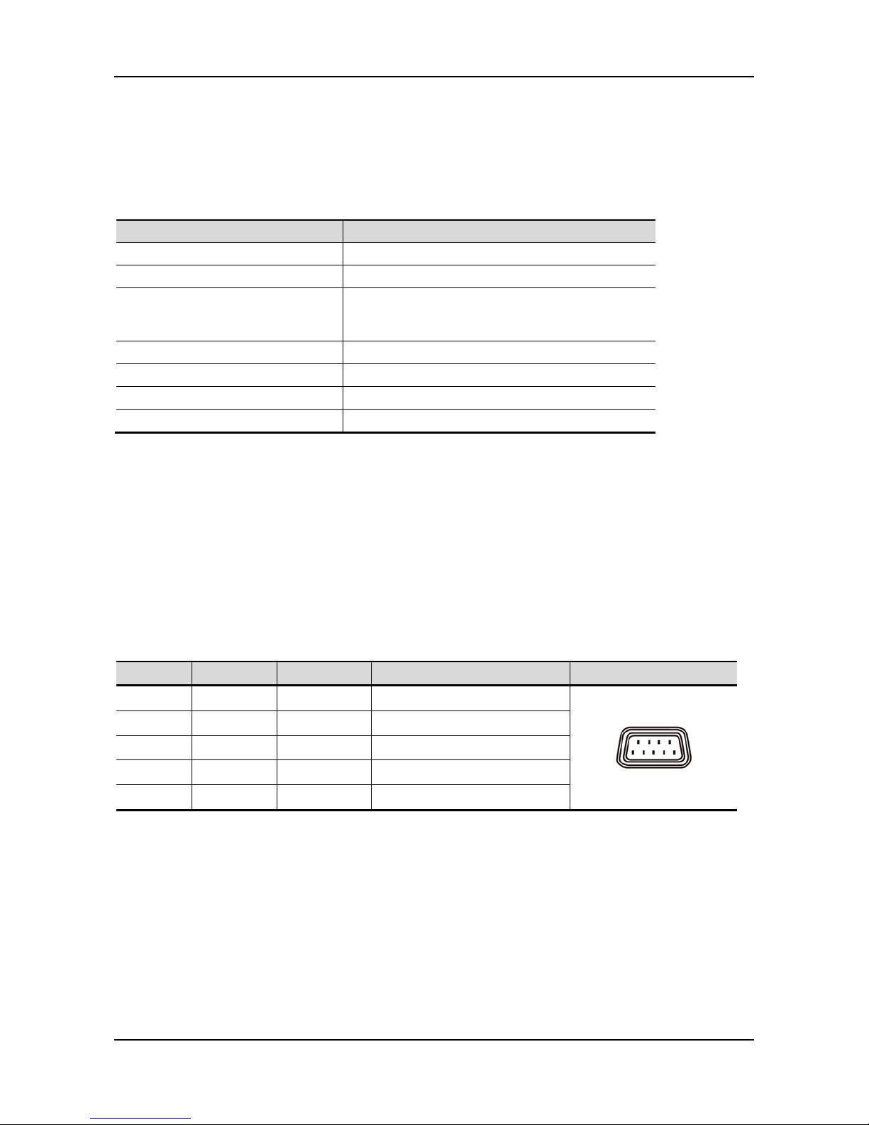
2.2 STANDARD INTERFACE......................................................................................................................................................4
2.3 USB2.0CONNECTOR TO PC/HOST...................................................................................................................................5
CHAPTER 3 INSTALLATION......................................................................6
3.1 PHYSICALFUNCTION.........................................................................................................................................................6
3.2 CONFIGURATION................................................................................................................................................................8
3.3 DRIVER INSTALLATION....................................................................................................................................................10
CHAPTER 4 CONFIGURE YOUR DEVICE...................................................11
4.1 BEFORE STARTING ........................................................................................................................................................... 11
4.2 CONFIGURE SYSTEM PARAMETERS ................................................................................................................................13
4.3 DEFINE WELCOME MESSAGE .........................................................................................................................................15
4.4 DEFINE YOUR OWN FONT...............................................................................................................................................15
CHAPTER 5 SOFTWARE SETTING COMMAND..........................................18
5.1 BAUD RATE SETTINGCOMMAND...................................................................................................................................18
5.2 PARITYCHECKSETTINGCOMMAND ..............................................................................................................................18
5.3 COMMANDTYPE SETTING COMMAND...........................................................................................................................19
5.4 INTERNATIONALCHARACTER SETSETTINGCOMMAND ...............................................................................................19
CHAPTER 6 COMMAND SET ....................................................................20
6.1 ESC/POSMODE COMMAND SET...................................................................................................................................20
6.2 ADM787/788MODE COMMAND SET............................................................................................................................22
6.3 EMAX(AEDEX) MODE COMMAND SET.....................................................................................................................23
6.4 UTCMODE COMMAND SET...........................................................................................................................................23
6.5 CD5220MODE COMMAND SET .....................................................................................................................................24
6.6 DSP-800 MODE COMMAND SET (OPTION).....................................................................................................................27
CHAPTER 7 CHARACTER SET..................................................................29
7.1 CHARACTER CODE (20H-7EH)........................................................................................................................................29
7.2 CHARACTER CODE PAGE (80H-FFH)..............................................................................................................................30

INTRODUCTION
1 CPD-3230 Customer Pole Display
CHAPTER 1
INTRODUCTION
Welcome
Thank you for choosing the CPD-3230 Customer Pole Display. The CPD-3230 is a 20 columns x 2 lines
customer display with Vacuum Fluorescent Display panel. VFD emits a very bright light with high
contrast. Based on VFD display method, the CPD-3230 gives a better view of message in bright blue-
green display fonts.
1.1 Unpacking
Confirm that all the following items are contained in the carton. If any item is missing or damaged,
contact the dealer from whom you purchased the product.
CPD-3230 Customer Pole Display Set:
Display Panel
Long Pole: 250 mm x 1
Short Pole: 117 mm x 1
Stand Base
Accessory Kit:
Quick Reference Guide
Driver CD
(User’s Manual included)
Dual Interface Cable

INTRODUCTION
CPD-3230 Customer Pole Display 2
1.2 Features
1. Vacuum Fluorescent Display
2. Eye-catching bright blue-green display font
3. Unique panel design to vitalize your retail interior.
4. Supports 14 language characters, including those from the USA, France, Germany, UK,
Sweden, Denmark I and II, Italy, Spain, Norway, Greek, Slavonic, Russian and
Portuguese.
5. Provides 6 command modes: EPSON ESC/POS, ADM787/788, UTC/S, UTC/P, EMAX
(AEDEX), CD5220 and DSP-800 (option).
6. The wide-range of power supplies input to prevent misuse.
7. Low power consumption achieves optimal energy use and reliability.
8. Innovative hinge design for quick panel adjustment.
9. User-programmable for all fonts and customer messages.
10. Hardware Interface:
Standard
Full speed data transfer using the USB 2.0 protocol.
RS-232C Interface with baud rates selectable from 9600 to 115200 bps.
11. Mechanical:
Provides a wide range of rotation and tilt angles.
Selectable pole length for best position installation.

INTRODUCTION
3 CPD-3230 Customer Pole Display
1.3 Specification
Model
CPD-3230
Display Method
Vacuum fluorescent Display text mode display panel
Number of Characters
40 characters (20 columns x 2 lines)
Display Color
Blue-green
Brightness
700 cd/m2
Font
I. 96 alphanumeric characters
II. 14 sets of international characters: USA, France, Germany, UK,
Sweden, Denmark I and II, Italy, Spain, Norway, Greek,
Slavonic, Russian and Portuguese
III. One set of user downloadable characters
Character Size
5x7 Dot Matrix
9.03 mm x 5.25 mm
Command Set
1. EPSON ESC/POS
2. ADM787/788 (option)
3. EMAX (AEDEX)
4. UTC/S, UTC/P
5. CD5220
6. DSP-800 (option)
Interface
RS-232C 9600/19200/38400/115200 bps
USB 2.0
Option
Pass-through: (1) RS232C (2) USB Hub
Power adapter
Power Supply
Power input via USB 5V
Power Consumption
3~5W
MTBF
25,000 hrs
Certification
CE/FCC Class A
Rotation Angle
Vertically: 0-36 degrees
Horizontal: 0-270 degrees
Physical Dimension
Head (W x D x H)
215 x 57 x 92 mm
Support (H x Ø)
Long: 250 x 34 mm; Short: 117 x 34 mm
Base (W x D x H)
200 x 120 x 27 mm
Weight
N.W. 1.0 kg
Environment
Operation Temperature
5~45℃
Storage Temperature
-20~70℃
Operation Humidity
15%~80% RH
Storage Humidity
10%~90% RH

INTERFACE
CPD-3230 Customer Pole Display 4
CHAPTER 2
INTERFACE
2.1 Communication Specification
RS232C Type
Data transmission
Serial
Synchronization
Asynchronous
Handshaking
None
Signal level
MARK = -3 to -15V (logical “1” OFF)
SPACE = +3 to +15V (logical “0” ON)
Baud rate
9600, 19200, 38400, 115200 bps
Parity
None, Even
Bit length (Data word length)
8 bits
Stop bits
1 bit
USB Type
The CPD-3230 series is compatible to the High-speed USB 2.0 protocol which has a raw
data rate of 12 megabits per second (Mbps).
2.2 Standard Interface
2.2.1 Serial RS232 connector to PC/HOST
Connector Type: D-sub 9Pin (Female)
Pin assignment
Pin No.
Signal
I/O
Function
Illustration
2
TXD
Output
Transmit Data
3
RXD
Input
Receive Data
4, 7
DTR/RTS
Output
Data Terminal Ready
5
GND
-
Ground
6,8
DSR/CTS
Input
Data Set Ready
NOTE: PIN9 DC input is necessarily required when DB9 functions as power source.
1 5
6 9

INTERFACE
5 CPD-3230 Customer Pole Display
2.2.2 Control Signal to Display Panel
Connector Type: 10Pin Phone Jack
Pin assignment
Pin No.
Signal
I/O
Function
Illustration
1
VIN
Input
+5V
2
GND
-
Ground
3
TXD
Output
Transmit Data
4
DTR
Data Terminal Ready
5
RXD
Input
Receive Data
6
DSR
Data Set Ready
7
USB
VBUS
8
USB
Data -
9
USB
Data +
10
GND
-
Ground
2.3 USB 2.0 connector to PC/Host
Connector Type: USB 2.0 B Type
Pin assignment
Pin No.
Signal
Illustration
Pin 1
VCC
Pin 2
Data –
Pin 3
Data +
Pin 4
GND
Type A

NSTALLATION
CPD-3230 Customer Pole Display 6
CHAPTER 3
INSTALLATION
The CPD-3230 Customer Pole Display is easy to install by following the instructions in
this chapter. No special training or tools are necessary. As this manual contains required
information on the installation and programming of CPD-3230 Customer Pole Display, it
is recommended that you read the entire manual carefully prior to initiating installations.
3.1 Physical Function
3.1.1 Display Dimension
Low
Middle
High
Highest

INSTALLATION
7 CPD-3230 Customer Pole Display
3.1.2 Assembling
Insert the RJ45 end of the dual interface cable through the base
and the pipe then into the panel and connect to the RJ45 slot. You
can extend the pole to the desired height by attaching the
extension pole for different heights:
Low 173 (mm), Mid 260 (mm), High 394 (mm) and Highest
482 (mm).
NOTE: Attach the joint of the extension pole or stand base
to the Display Panel until it is properly locked.
3.1.3 Rotation
This product allows a 270 degree rotation in either horizontal direction.
ATTENTION
(1) Violently rotating the Display Panel may cause damages of
the Display Panel.
(2) Secure the Display Panel properly after attaching the
extension pole to a desired height.
3.1.4 Angling
This product allows 0~36 degree tilt angle adjustment. The Display Panel can be easily
tilted to the desired position by using a hinge design.
How to Adjust
(1) Locate the hinge section on the backside of Display Panel.
(2) Pull the tab downward and tilt the panel up or down to the desired position.

NSTALLATION
CPD-3230 Customer Pole Display 8
3.2 Configuration
3.2.1 USB Connection
Step 1 Turn OFF the system power
Before you start the installation, ensure that the host computer and the CPD-3230
Customer Pole Display are powered off.
Step 2 Connect the USB cable
Step 3 Start the host PC and switch on the display.

INSTALLATION
9 CPD-3230 Customer Pole Display
3.2.2 RS232 Connection
Step 1 Turn OFF the system power
Before you start the installation, ensure that the host computer and the CPD-3230
Customer Pole Display are powered off.
Step 2 Connect the RS232 cable
Plug the DB9 Female connector of RS232 cable and only the 5V USB cable to host PC.
Now you are ready for power-up.
Step 3 Start the host PC and switch on the display.
ATTENTION
With the dual interface cable, the CPD-3230 is able to be powered only by the USB 5V.

NSTALLATION
CPD-3230 Customer Pole Display 10
3.3 Driver Installation
The firmware for the USB port is divided
into CDC class (Virtual COM) and printer
class. To recognize which firmware version
it is, check the starting status of your
customer display as Pic 1:
The version affix F or H : CDC Class.
The version affix E or G : Printer Class.
In case your USB port is in CDC class and
your application software is connected by
USB port, you must install the driver:
-Click CDC Class as Pic 2.
-check the device manager to find the
COM port number as below.
If your Application Software needs
to install the printer mode driver:
Click Printer Class as Pic 2 and select as
shown in the Pic 3,4:
-Serial/Virtual for COM Connection.
-USB for USB Connection.
Pic 1
Pic 2
Pic 3
Pic 4

CONFIGURE YOUR DEVICE
11 CPD-3230 Customer Pole Display
CHAPTER 4
CONFIGURE YOUR DEVICE
The system parameters of CPD-3230 can be set by using VFD Utility software tool. You
can find the tool in the companion disk. In addition to setting system parameters, you
can configure welcome message and user font with the software tool. The system
parameters include the following items.
Language Character Set
Command Type
Baud rate
Parity Check
4.1 Before starting
Before starting the software, please make sure the CPD-3230 is connected to your PC
and it works. If you use USB interface or device driver, please install device driver
before starting the software. If the connection is OK, execute the software.
4.1.1 Select a proper interface
After starting the software, the following dialog will pop up. Select a proper interface.

CONFIGURE YOUR DEVICE
CPD-3230 Customer Pole Display 12
4.1.2 RS-232 Interface
If you select the item COM port (RS232 only), the dialog of RS-232 setting will show up
the guide you configure the RS-232 interface. Please make sure the parameters that
same, the communication between host PC and your machine will fail.
4.1.3 Selecting Device Driver
Please select your device from the pull-down list on following dialog. If the device driver
is installed, your device shall be shown on the list.
4.1.4 Select Model Name
model. The model name can be selected on the upper-right corner of the window. If the
model name does not match with your device, the configuration may not take effect.
Pole Display 20x2

CONFIGURE YOUR DEVICE
13 CPD-3230 Customer Pole Display
4.2 Configure System Parameters
There are three pages on the main dialog. The first one is the Configuration Page. You
can select desired character type, command set and baud rate of RS-232 interface.
After all items are set to desired condition, press SET button to send all the settings to
your device. These settings will be stored on the non-volatile memory. Every time when
you start the device, these settings will be retrieved from non-volatile memory.

CONFIGURE YOUR DEVICE
CPD-3230 Customer Pole Display 14
4.2.1 Command Type
The CPD-3230 supports up to 7 command sets. They are listed on the following table.
Please select one from the pull-down list.
Command Type
Default
EPSON ESC/POS
*
DSP-800(option)
ADM787/788
EMAX(AEDEX)
UTC/S
UTC/P
CD5220
Reserved
4.2.2 Language Character Set Selection
The CPD-3230 supports the following language character set. Please refer to following
table for character code page.
Character Set(20h-7Fh)
Code Table (80H-FFH)
Default
U.S.A
PC-437 (USA, Standard Europe)
*
France
PC-858
Germany
U.K.
Denmark I
Sweden
Italy
Spain
Reserved
Norway
PC-858
Denmark II
U.S.A
Slavonic
U.S.A
Russia
U.S.A
PC-860 (Portuguese)
U.K.
Greek
User Font
4.2.3 Baud Rate Selection
Baud Rate (bps)
Default
9600
*
19200
38400
115200

CONFIGURE YOUR DEVICE
15 CPD-3230 Customer Pole Display
4.2.4 Parity Check Selection
Parity Check
Default
None-parity
*
Even-parity
4.3 Define Welcome Message
You can define your own message in the display. The Msg1 is displayed steadily on
upper line while the Msg2 is displayed on lower line in marquee status.
You can type the character on keyboard in ASCII mode or type others in Hex mode.
Press Set button to send the messages to the machine.
4.4 Define Your Own Font
You can create your own font and download it with the software tool.
There are three ways to create the font:
Table of contents
Other Appostar Monitor manuals