manuals.online logo
Brands
  1. Home
  2. •
  3. Brands
  4. •
  5. Appsys ProAudio
  6. •
  7. Adapter
  8. •
  9. Appsys ProAudio MTA-64 User manual

Appsys ProAudio MTA-64 User manual

MTA-64
MADI-TP Adapter for
DiGiCo/Soundcraft/Studer/Harman
User's Manual
multiverter
User's Manual
Table of Contents
1 GENERAL 3
1 1 Purpose 3
1 2 Box Contents 3
1 3 Conventions used in this manual 3
2 DEVICE DESCRIPTION 4
2 1 LED indications 4
3 PREREQUISITES 5
3 1 Multiverter Firmware Check 5
4 OPERATION 6
4 1 Connection 6
4 2 Connecting two MTA-64s 6
4 3 Software setup 7
Web7
Front panel8
Command line8
5 CONFIGURING A SECOND MTA-64 10
5 1 Changing the MTA-64's address via jumper 10
5 2 Pinswap cable 10
6 SPECIFICATIONS 11
7 APPENDIX 12
71 Warranty 12
72 Manufacturer contact 12
73 FCC Compliance 12
74 Recycling 13
75 Document Revision History 13
76 About this document 13
2
MVR-64
1. GENERAL
1.1. Purpose
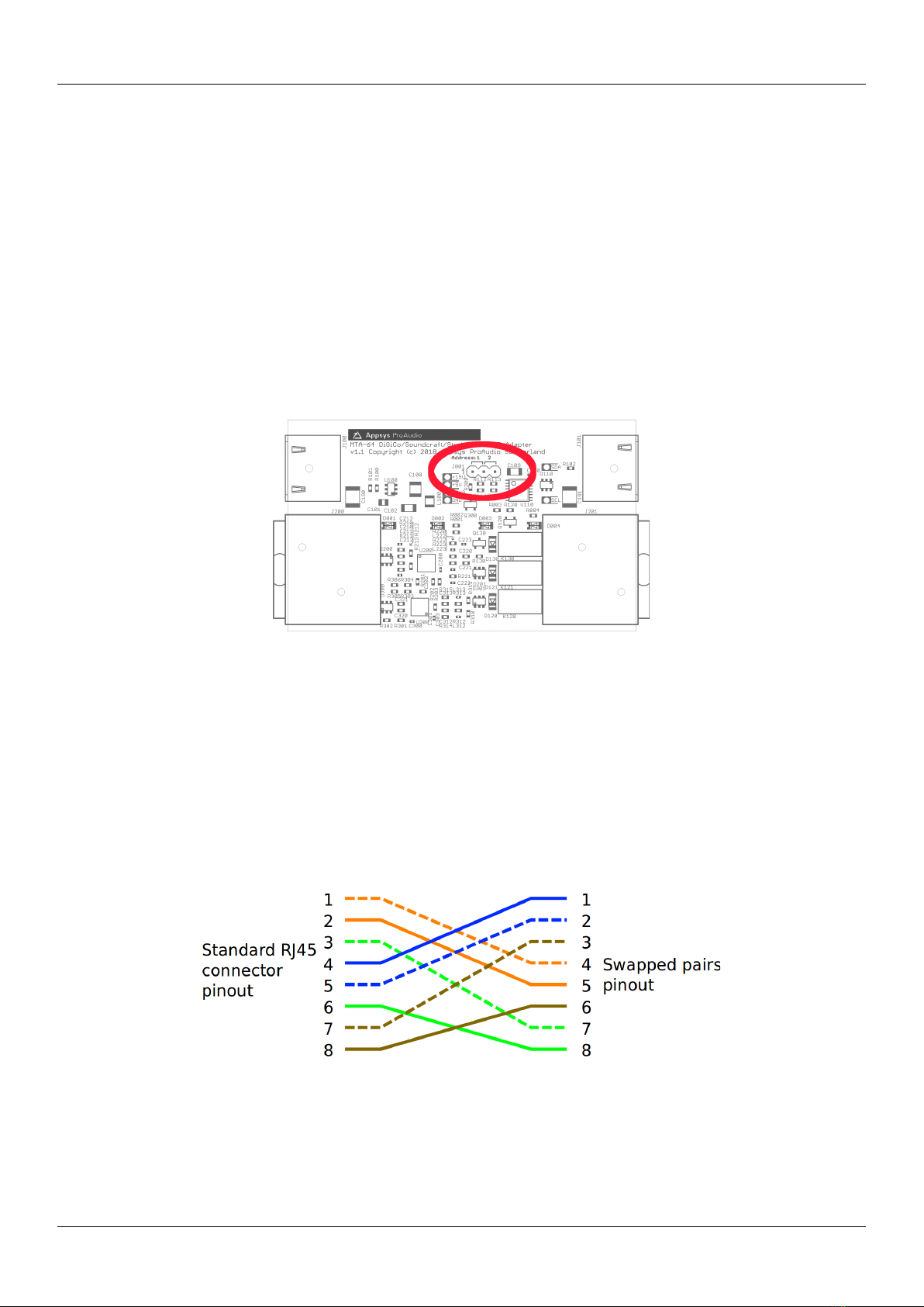
With the MTA-64, the multiverter becomes capable of connecting to the MADI-TP
variants used in DiGiCo and Soundcraft/Studer/Harman desks, which - although
not ocially standardized - have gained widespread acceptance because they are
built into many desks and stageboxes The MTA-64s relay logic eliminates the
need for crossover cables and allows to use standard straight (1:1) cabling in all
situations
The MTA-64 connects to the multiverter's MADI-TP port (for the audio
transmission) and to the EXTENSION port (for power supply and mode control)
The EXTENSION port is fed through on the MTA-64 to allow other extension boxes
(e g for AVB) to connect to the multiverter simultaneously Optionally, a second
MTA-64 may be connected to the MVR-64 to add another MADI-TP port (instead of
the AES50 port)
1.2. Box Contents
1 MTA-64 Adapter Box
1 Cat5 cable 0 5m / 1 7 ft
1 HDMI cable 0 5m / 1 7 ft with locking screws
This manual
1.3. Conventions used in t is manual
A button on the front of the multiverter is shown like this: Set
A particular LED on the front of the device is shown like this: ☼ WCLK
Text indicated on the seven-segment display is shown as 02
Operations in a particular control method are indicated by a triangle:
Front panel,  Web or Command line 
Filled circles with an exclamation mark indicates an action that
must be performed (“Required”)
A section marked with a “information” icon indicates
a useful tip
3
User's Manual
2. DEVICE DESCRIPTION
Top view
Connectors on "MVR" side Connectors on "Console/Stage" side
2.1. LED indications
LED Meaning
DiGiCo (blue) DiGiCo mode selected
Sc/St (white) Soundcraft/Studer/Harman mode selected
MDIX (yellow) Crossover configuration (Receive/Transmit swapped)
When lit, a crossover cable is emulated on the "Console/Stage" port
RxD (green) Receive Data OK (same as MADI-TP "green" indication on MVR front)
When lit, the MTA-64 is configured correctly and receives a signal
4
MVR-64
Extension-Port
MVR-64
MADI-TP Port
Optional: Extension-
Box or 2nd MTA-64
Console or
Sta ebox
MADI-TP Port
MVR-64
3. PREREQUISITES
3.1. Multiverter Firmware C eck
The multiverter requires at least firmware 4.0 for the
MTA-64 to work Please check and update if required (see
below)
To check the multiverter's firmware version: Press Recall , move to
☼ Function , press OK , move to ☼ 12 , press OK , move cursor to ☼ AD
If the seven-segment display shows 04 or higher, no update is required
If 03 or less is shown, a firmware update is required Download the firmware
update from our website and follow the instructions in the README TXT file
contained in the package
5
User's Manual
4. OPERATION
4.1. Connection
Connect the Cat5 port on the MVR side of the MTA-64 to the MADI-TP port of
the multiverter
Connect the Extension port on the MVR side of the MTA-64 to the xtension port
of the multiverter
Connect the Cat5 port on the Console / Stage side of the MTA-64 to the console
or stagebox:
4.2. Connecting two MTA-64s
The second MTA-64 needs to be jumpered to address 2 and connected to the
AES50 port (which must be set to MADI-TP mode) A pinswap cable is required
between the AES50 port and the MTA-64 See chapter 5 "Configuring the second
MTA-64" for details
6
MVR-64
multiverter
MVR-64
multiverter MTA-64
MTA-64
Cat5
Console
or Sta ebox
Console
or Sta ebox
Cat5
HDMI
Extension
MADI-TP
(optional)
Extension
Box (e. . AVB)
Extension
Box (e. . AVB)
MVR-64
multiverter
MVR-64
multiverter
MTA-64
MTA-64
Cat5
Console
or Sta ebox #1
Console
or Sta ebox #1
Cat5
HDMI
Extension
MADI-TP
Extension
Box (e. . AVB)
Extension
Box (e. . AVB)
MTA-64
(address 2)
MTA-64
(address 2)
Console
or Sta ebox #2
Console
or Sta ebox #2
Cat5
(pinswap)
HDMI
Cat5
AES50
(in TP mode)
MVR-64
4.3. Software setup
The easiest way of setting up the MTA-64 is by using the
multiverter's web configuration Simply type the IP address
of the Dante module in your web browser and open the
SETTINGS page
Web
The settings [04] and [05] can be altered on the "SETTINGS" page:
7
User's Manual
Front panel
The mode setting is available through the "Function" menu To adjust the value:
Press the blue Recall button
Move the cursor to ☼ Function by turning the encoder left or right
Confirm OK (push the encoder)
The ☼ Function LED should now be lit
Move the cursor to index ☼ 4 (MADI-TP operation mode) and push the
encoder knob* The seven-segment display is now blinking, indicating the
current mode number (see Table 1 on page 9)
Rotate the encoder to alter the value
Confirm OK (push the encoder) or press ⮌ Back to cancel the operation
Command line
function 04 <value>
with <value> according to Table 1 on page 9 *
* Index 05 is used to configure a second MTA-64 connected to the AES50 port
8
MVR-64
Value Mode Num.
C
96k frame
format
Pinout mode Remarks
00 AES-X213 56 48k Auto connect directly (without MTA-64)
01 96k
02 64 48k
03 96k
04 AES50 48 - connect directly (without MTA-64),
use pinswap cable
08 DiGiCo 56 48k Straight
09 96k
10 64 48k
11 96k
12 Soundcraft/Studer 56 48k
13 96k
14 64 48k
15 96k
24 DiGiCo 56 48k MDIX (Crossover)
25 96k
26 64 48k
27 96k
28 Soundcraft/Studer 56 48k
29 96k
30 64 48k
31 96k
32 AES-X213 57 48k Auto connect directly (without MTA-64)
33 96k
40 DiGiCo 57 48k Straight
41 96k
44 Soundcraft/Studer 57 48k
45 96k
56 DiGiCo 57 48k MDIX (Crossover)
57 96k
60 Soundcraft/Studer 57 48k
61 96k
Table 1: Mode numbers (numbers not listed are reserved)
9
User's Manual
5. CONFIGURING THE SECOND MTA-64
5.1. C anging t e MTA-64's address via jumper
The second MTA-64 needs to be jumpered internally to address "2" The jumper is
located on the internal PCB To access it:
1 Remove the four screws (two upper screws on each side)
2 Remove the top cover
3 Locate the jumper on the top and change it to position "2":
5.2. Pinswap cable
The AES50 port has a dierent pinout and requires a pin swap Cat5 cable between
the MVR-64 and the MTA-64 (Note: this is the same cable which is required to use
the MADI-TP port as AES50)
10
MVR-64
6. SPECIFICATIONS
Parameter Value
Dimensions 83x39x52mm (WxHxD)
Weight 128 g
Operating
temperature
0 +70°C, non-condensing
Storage temperature -40 +85°C, non-condensing
Power consumption +15V DC from multiverter, 2W max
Cable lengths MVR-64 to MTA-64 / Cat5 5m max
MVR-64 to MTA-64 / HDMI 5m max
MTA-64 to Console/Stagebox 70 100m
(depends on cable quality and counterpart)
Channel count Up to 64x64 in x1 modes (44 1 / 48 kHz)
Up to 32x32 in x2 modes (88 2 / 96 kHz)
Up to 16x16 in x4 modes (176 4 / 192 kHz)
Sample rates Arbitrary sample rates between 32kHz and 192kHz
Remote Control Data Transparent forwarding of DiGiCo remoting data (contained in ch57),
Soundcraft/Studer remoting data (userbits of ch1-10) and others
Latency The latency added by the MTA-64 is negligible (in the nanoseconds range)
Pinout Pin number/
color
MVR side Console/Stage side
DiGiCo DiGiCo MDIX Soundcraft Soundcraft
MDIX
1 (orange/wt) TX+ RX+ TX+ RX+
2 (orange) TX- RX- TX- RX-
3 (green/wt) RX+ TX+
4 (blue/wt) TX+
5 (blue) TX-
6 (green) RX- TX-
7 (brown/wt) RX+ RX+ TX+
8 (brown) RX- RX- TX-
Note: The signals on the "MVR" side are electrically dierent from the "Console/Stage"
side
11
User's Manual
7. APPENDIX
7.1. Warranty
We oer a full two (2) year warranty from the date of purchase Within this period,
we repair or exchange your device free of charge in case of any defect* If you
experience any problems, please contact us first We try hard to solve your
problem as soon as possible, even after the warranty period
* Not covered by the warranty are any damages resulting out of improper use,
willful damage, normal wear-out (especially of the connectors) or connection with
incompatible devices
7.2. Manufacturer contact
Appsys ProAudio
Rolf Eichenseher
Bullingerstr 63 / BK241
CH-8004 Zürich
Switzerland
www appsys ch
info@appsys ch
Phone: +41 43 537 28 51
Mobile: +41 76 747 07 42
7.3. FCC Compliance
This equipment has been tested and found to comply with the limits for a class B
digital device, pursuant to part 15 of the FCC Rules These limits are designed to
provide reasonable protection against harmful interference in a residential
installation This equipment generates, uses and can radiate radio frequency
energy and if not installed and used in accordance with the instructions, may
cause harmful interference to radio communications However, there is no
guarantee that interference will not occur in a particular installation If this
equipment does cause harmful interference to radio or television reception, which
can be determined by turning the equipment o and on, the user is encouraged to
try to correct the interference by one or more of the following measures:
Reorient or relocate the receiving antenna
Increase the separation between the equipment and receiver
Connect the equipment into an outlet on a circuit dierent from that to which
the receiver is connected
Consult the dealer or an experienced radio/TV technician for help
This equipment has been verified to comply with the limits for a class B computing
device, pursuant to FCC Rules In order to maintain compliance with FCC
regulations, shielded cables must be used with this equipment Operation with
non-approved equipment or unshielded cables is likely to result in interference to
radio and TV reception The user is cautioned that changes and modifications
12
MVR-64
made to the equipment without the approval of manufacturer could void the user’s
authority to operate this equipment
7.4. Recycling
According to EU directive 2002/96/EU, electronic devices with a
crossed-out dustbin may not be disposed into normal domestic
waste
Please return the products back for environment-friendly
recycling, we'll refund you the shipping fees
7.5. Document Revision History
2: Corrected 96k frame format in Table 1
1: Initial release
7.6. About t is document
All trademarks mentioned in this document are property of the respective owners
All information provided here is subject to change without prior notice
Document Revision: 2 · 2019-08-07
Copyright © 2019 Appsys ProAudio · Printed in Switzerland
13

Other manuals for MTA-64

1

Popular Adapter manuals by other brands

ABB Tina 2A product manual

ABB

ABB Tina 2A product manual

TP-Link TL-WPA7517 Quick installation guide

TP-Link

TP-Link TL-WPA7517 Quick installation guide

NETGEAR GA511 - Gigabit Ethernet PC Card user manual

NETGEAR

NETGEAR GA511 - Gigabit Ethernet PC Card user manual

Amer 1907GA1200T6380 user guide

Amer

Amer 1907GA1200T6380 user guide

Mitsubishi Electric PAC-SE55RA-E installation manual

Mitsubishi Electric

Mitsubishi Electric PAC-SE55RA-E installation manual

Allen-Bradley PowerFlex 20-COMM-D user manual

Allen-Bradley

Allen-Bradley PowerFlex 20-COMM-D user manual

Saramonic SmartRig user manual

Saramonic

Saramonic SmartRig user manual

IntraServer Technology ITIpci 5232E Installation and user guide

IntraServer Technology

IntraServer Technology ITIpci 5232E Installation and user guide

OPTOGAMA MSTAGE Series manual

OPTOGAMA

OPTOGAMA MSTAGE Series manual

Steren ELI-1240 instruction manual

Steren

Steren ELI-1240 instruction manual

Tektronix Keithley 8680 instruction sheet

Tektronix

Tektronix Keithley 8680 instruction sheet

NETGEAR EPS90W installation guide

NETGEAR

NETGEAR EPS90W installation guide

RKI Instruments 30-0954RK-282ST Series Operator's manual

RKI Instruments

RKI Instruments 30-0954RK-282ST Series Operator's manual

Hioki Z3230 instruction manual

Hioki

Hioki Z3230 instruction manual

SSS Siedle VA/GU 511-0 Product information

SSS Siedle

SSS Siedle VA/GU 511-0 Product information

Panasonic DMW-DCC17 user manual

Panasonic

Panasonic DMW-DCC17 user manual

iSystem CoreSight 20-pin user manual

iSystem

iSystem CoreSight 20-pin user manual

Premier Mounts UFP-280 installation instructions

Premier Mounts

Premier Mounts UFP-280 installation instructions

manuals.online logo
manuals.online logoBrands
  • About & Mission
  • Contact us
  • Privacy Policy
  • Terms and Conditions

Copyright 2025 Manuals.Online. All Rights Reserved.