Aprimatic T4 User manual

A0352000000
T4-PROFESSIONALE
Istruzioni per l’installazione
Installation instructions
Instructions pour l’installation
Montageanleitung
Instrucciones para la instalación
I
GB
F
D
E

© Aprimatic S.p.A., 1999.Tutti i diritti riservati.
Nessuna parte di questo documento può essere copiata o tradotta in altre lingue o formati senza il
consenso scritto di Aprimatic S.p.A.
Lespecifichedel prodotto sono soggetteamodifiche senza preavviso.Pertantoilpresente documento
potrebbe non corrispondere esattamente alle caratteristiche del prodotto.
Licenze e marchi
Il logotipo “Aprimatic” è un marchio registrato di Aprimatic S.p.A.
Cod. A0352000000
Stampato in Italia
© Aprimatic S.p.A., 1999.Tous droits réservés.
Aucune partie du présent document ne peut être dupliquée ou traduite dans d’autres langues sans
l’autorisation écrite d’Aprimatic S.p.A.
Les caractéristiques du produit peuvent être soumises à modifications sans préavis. Le présent
document peut de ce fait ne pas correspondre exactement aux caractéristiques du produit.
Licences et marques
Le logotype «Aprimatic» est une marque déposée d’Aprimatic S.p.A.
Réf. A0352000000
Imprimé en Italie
© Aprimatic S.p.A., 1999.Todos los derechos reservados.
Queda prohibido copiar o traducir a otros idiomas o formatos cualquier parte de este documento sin
la autorización escrita de Aprimatic S.p.A.
Las características técnicas del producto pueden modificarse sin previo aviso; por consiguiente el
presente documento podría no corresponder exactamente a las características del producto.
Patentes y marcas
El logotipo «Aprimatic» es una marca registrada de Aprimatic S.p.A.
Cód. A0352000000
Impreso en Italia
© Aprimatic S.p.A., 1999. All rights reserved.
No part of this document may be reproduced or translated into any other language or form without
the written permission of Aprimatic S.p.A.
The product specifications may be modified without prior notice. Therefore this document may not
correspond exactly to the characteristics of the product.
Licences and trademarks
The logo “Aprimatic” is a trademark registered by Aprimatic S.p.A.
Code A0352000000
Printed in Italy
© Aprimatic S.p.A., 1999. Alle Rechte vorbehalten.
Jede Vervielfältigung oder Übersetzung in andere Sprachen bzw. Formate, auch auszugsweise,
muß von Aprimatic S.p.A.schriftlich genehmigt werden.
Änderungen ohne Vorankündigung vorbehalten. Es sind daher Abweichungen zwischen den hier
angegebenen Daten und den Daten des Produkts möglich.
Lizenzen und Warenzeichen
Das Logo „Aprimatic“ ist ein eingetragenes Warenzeichen der Aprimatic S.p.A.
Code A0352000000
Gedruckt in Italien
I
GB
F
D
E

1
Sommario
1. DESCRIZIONE ........................................................................................... 2
1.1 Schema a blocchi dell’apparecchiatura .............................................. 2
2. INSTALLAZIONE ........................................................................................ 2
2.1 Preparazione ..................................................................................... 2
2.2 Montaggio .......................................................................................... 2
2.3 Collegamentielettrici ......................................................................... 2
3. MESSA IN FUNZIONE ............................................................................... 3
3.1 Prove di funzionamento ..................................................................... 3
3.2 Regolazioni ........................................................................................ 3
3.3 Programmazione del funzionamento.................................................. 3
3.4 Impostazioni / settaggi / selezioni ...................................................... 4
4. CONTROLLO DEL FUNZIONAMENTO ...................................................... 4
4.1 Verifica del funzionamento dei dispositivi esterni ............................... 4
5. COLLEGAMENTO SCHEDE OPZIONALI................................................... 5
5.1 Scheda ES per semaforo unidirezionale ............................................ 5
Norme di sicurezza
• Eseguire gli interventi come specificato dal costruttore.
• L’installatore deve verificare l’installazione e il corretto funzionamento dell’apparec-
chiatura.
• E’vietato utilizzare il prodotto per scopi diversi da quelli previsti o impropri.
• E’vietato manomettere o modificare il prodotto.
• Utilizzare ricambi originali.
• Delimitare la zona d’intervento per evitare l’accesso a persone estranee.
• Lazonad’interventodeve essere privadi ostacoli e con pavimentonon sdrucciolevole.
• Utilizzare attrezzature in buono stato.
• E’ vietato operare in ambiente non sufficientemente illuminato e non idoneo per la
salute.
• E’vietato il transito da parte di estranei nella zona di intervento.
• E’vietato lasciare incustodita la zona di lavoro.
Scopo del manuale
Questo manuale è stato redatto dal costruttore ed è parte integrante del prodotto.
Le informazioni in esso contenute sono indirizzate agli operatori esperti che eseguono
l’installazione e la manutenzione straordinaria. Essi devono possedere competenze
specifiche e particolari capacità per eseguire correttamente e in sicurezza gli interventi
di loro competenza.La costante osservanza delle informazioni contenute nel manuale
garantisce la sicurezza dell’uomo, l’economia di esercizio e una più lunga durata di
funzionamento del prodotto.Al fine di evitare manovre errate e il conseguente rischio di
incidenti, è importante leggere attentamente questo manuale, rispettando scrupolo-
samente le informazioni fornite.
Campo di applicazione
Apparecchiatura per operatori Aprimatic per l’azionamento di battenti.
ITALIANO
Aprimatic S.p.A. • Zona Industriale Fossatone
40060 Villa Fontana • Medicina • Bologna (ITALY)
tel.051.6979511 • fax 051.6930396

1. DESCRIZIONE
Apparecchiatura alimentata a tensione di rete di 230VAC 50Hz, dedicata al pilotaggio e
controllo di cancelli a battente mossi da operatori elettromeccanici alimentati a 24VDC.
Consumo in stand-by 15 Watt.Potenza massima degli operatori/motori 520 Watt max.
Tuttii modi di funzionamento,la regolazione dei parametrieleimpostazionidellefunzioni
avvengono tramite un dispositivo denominato PROGRAMMATORE, in dotazione
esclusivamente agli installatori qualificati APRIMATIC.
1.1 SCHEMA A BLOCCHI DELL’APPARECCHIATURA
T4Prof.EPS
ST1 Led ingresso Start
ST2 Led ingresso Start pedonale/
Chiude
STOP Led ingresso stop
FOTO Led ingresso fotocellula standard
F.IN Led ingresso fotocellula
supplementare
F.C.M1 Led ingresso finecorsa motore 1
F.C.M2 Led ingresso finecorsa motore 2
POWER Led alimentazione 24 VDC
presente
K1 Relé abilitazione motore 1
K2 Relé abilitazione motore 2
K3 Relé direzione motore 2
K4 Relé direzione motore 1
K5 Relé elettroblocco
J1 Morsettiera segnali
J2 Morsettiera potenza
J3 Connettore innesto radioricevente
J4 Connettore per schede
supplementari
CB Morsettiera collegamento
caricabatterie
M1 Morsetti collegamento motore 1
M2 Morsetti collegamento motore 2
20VAC Morsetto secondario trasformatore
F1 Fusibile 3,15A rete
F2 Fusibile 16A bassa tensione 20
VAC
F3 Fusibile 8A motore 1
F4 Fusibile 8A motore 2
F5 Fusibile 2A elettroblocco
F6 Fusibile 2A logica e accessori
2. INSTALLAZIONE
ATTENZIONE - L’installazione del prodotto può essere effettuatasoltantodapersonale
tecnico qualificato del servizio di assistenza e/o montaggio.
ATTENZIONE - L’impianto elettrico dovrà essere realizzato in conformità con le
normative in vigore nel paese di installazione.
ATTENZIONE - Togliere sempre tensione prima di aprire il contenitore.
Il connettore per il programmatore è
posto a bordo della scheda CPU

ITALIANO
T4PROFMO.EPS
2.1 PREPARAZIONE
Prima di procedere al montaggio dell’apparecchiatura, preparare gli utensili necessari per il
fissaggio a parete e per i collegamenti elettrici. Sono inoltre necessari i seguenti dispositivi:
1. tasselli a espansione Ø 6 mm
2. pressacavi PG16 di tipo skintop
3. un interruttore omnipolare con apertura minima dei contatti di 3 mm
4. un pulsante di emergenza
5. cavi per uso esterno approvati di 0,75 minimo e 2,5 mm² di sezione
2.2 MONTAGGIO
Per fissare l’apparecchiatura non è necessario praticare fori.
1. Fissarel’apparecchiaturaadun’altezza di almeno30cm,utilizzando iforidifissaggio
del contenitore plastico.
2. Inserire i cavi di collegamento, utilizzando i fori prestampati presenti sul fondo del
contenitore e i pressacavi indicati.
3. Installare a monte dell’apparecchiatura l’interruttore omnipolare.
4. Installare un pulsante di emergenza in posizione tale da consentire la vista del
sistema di automazione e in modo tale da togliere completamente alimentazione
all’impianto.
5. Utilizzareicavida 2,5 mm² di sezione minimaperilcollegamentodell’alimentazione
deimotorialla centralina;per collegamenti superiori ai6 m.siconsiglia l’usodi cavi
da 4 mm² di sezione. Utilizzare i cavi da 0,75 mm² per il collegamento degli altri
dispositivi a 24 VDC.
2.3 COLLEGAMENTI ELETTRICI
ATTENZIONE - Prima di procedere al collegamento è necessario interrompere
l’alimentazione elettrica di rete.
ATTENZIONE - Non utilizzare cavi citofonici o telefonici.
Effettuare i collegamenti elettrici come indicato nello schema riportato qui di fianco.
NOTA - Come previsto dalle norme vigenti, fascettare separatemente i cavi di
collegamento relativi ai comandi (morsetti da 1 a 14) rispetto ai cavi di
potenza (morsettiere M1 e M2).
N.B. Tutti i contatti N.C. di sicurezza (Stop, fotocellule e finecorsa motori) se non
utilizzati dovranno essere ponticellati.
ATTENZIONE!
Fascettare saldamente fra loro i cavi a bassa tensione in prossimità della morsettiera
J1.Fascettare saldamente fra loro i cavi di potenza in prossimità della morsettiera J2.
2
Ritardo in apertura
20 VAC - Dal secondario del trasformatore
Al primario del trasformatore
230 V - 50 Hz
N
F
N
F
Finecorsa motore 2
Elettroserratura
Finecorsa motore 1
Lampeggiatore a LED
Lampada spia max 3 W
Alimentazione accessori
Comune ingressi
Fotocellula sicurezza in apertura
Fotocellula
Stop
Start pedonale / Chiude
Start
J2
J1
4
15
+
+
+
+
17
2
3
5
16
-
-
-
-
1
9
12
13
14
7
10
8
11
6
18
M2
M1
+
-
-
+
-
+
Ritardo in chiusura
Dal circuito caricabatterie

3 MESSA IN FUNZIONE
Dopo aver completato la connessione come indicato e verificato accuratamente i
collegamentielettrici, riattivarel’alimentazione di rete e verificareche l’impiantofunzioni
correttamente come spiegato qui di seguito.
3.1 PROVE DI FUNZIONAMENTO
Al termine dei collegamenti si deve procedere al controllo del sistema di automazione,
verificando che premendo il pulsante di start l’automazione si apra. Se, invece,
l’automazione si chiude, è necessario invertire i collegamenti dei motori.
3.2 REGOLAZIONI
L’utilizzo del programmatore permette di regolare il tempo e la modalità di lavoro
dell’automazione.
ATTENZIONE - Il connettore è polarizzato ed ha una modalità di inserimento univoca
che va rispettata; se l’inserimento appare forzato controllare il verso
di innesto.
NOTA - Il numero indicato davanti alla descrizione di ciascun parametro è il numero
cheindicala funzione in cui si staoperando.I valori sono visualizzati sul display
del PROGRAMMATORE (2 digit di sinistra).
Fra parentesi quadra è indicato il range impostabile, tramite il
PROGRAMMATORE (2 digit di destra).
10 – RITARDO D’ANTA IN APERTURA (0 – 20 s) [Range: 0 – 20]
Ritardail movimentoinaperturadi un’anta rispetto all’altra dellastessaautomazione.
11 – RITARDO D’ANTA IN CHIUSURA (0 – 20 s) [Range: 0 - 20]
Ritarda l’avvio in chiusura di un’anta rispetto all’altra della stessa automazione.
12 - VELOCITA’AVVICINAMENTO/RALLENTAMENTO [Range:0 – 20]
A fine corsa (apertura o chiusura) il moto rallenta. Evita lo sbattere delle ante.
Attuabile solo con attuatori dotati di fine corsa.
13 –TEMPO DI PAUSA (2 – 180 s) [Range: 1 – 90]
Nelmododifunzionamentoautomaticoregolailtempo di sosta con anta/e aperta/e.
14 –TEMPO DI LAVORO (2 – 180 s) [Range:1 – 90]
Regola il tempo di lavoro degli attuatori, utile in special modo per operatori privi di
fine corsa.
15 – RITARDO ATTIVAZIONE FRENO (0 – 2 s) [Range: 0 – 20]
Funzione utilizzata solo per scorrevoli.
AUTOMATICO SUPER [25 – 02]
Selezionando questo tipo di funzionamento, quando viene inviato un impulso di start, si
comanda l’apertura fino a finecorsa, il cancello rimane aperto per il tempo di pausa
predeterminato e quindi si chude automaticamente.
In qualunque fase un impulso di start inverte il moto corrente: è possibile la chiusura a
comando.
• Infasedi pausa un eventuale impulso avvia il prelampeggio e lasuccessivachiusura.
NOTA - Nei modi Automatico e Automatico Super le fotocellule possono essere
impostatecome da funzione 43.L’impostazione della fotocellulaè PRIORITARIA
sulla logica di funzionamento.
DIAGNOSTICA [25 – 03]
Laroutinedi diagnostica consente di verificare il corretto funzionamento dituttele uscite
e di tutti gli ingressi con la seguente modalità.
Ilmicroprocessore, dapprima,attivainsequenza tutte le uscite(relè abilitazione motore
1, relè abilitazione motore 2, relè direzione motore 1, relè direzione motore 2, relè
elettroblocco, lampeggiatore, lampada spia) e poi si pone in condizione di attesa
dell’attivazionedegli ingressi;se entro i 10 secondi successivi al termine dellaroutine di
test delle uscite nessun ingresso viene attivato, la sequenza di attivazione delle uscite
vieneripetuta.
Se invece viene attivato un ingresso, in caso di diagnostica OK, il microprocessore
comanda un numero di cicli completi di lampeggio (0,5 s ON e 0,5 s OFF), pari al
numero progressivo dell’ingresso attivato (start=1, start pedonale/chiude=2, stop=3,
fotocellula standard=4, fotocellula supplementare=5, finecorsa motore 1=6, finecorsa
motore 2=7).
SEMIAUTOMATICO APRE/CHIUDE [25 – 04]
Selezionandoquesto tipodifunzionamentoilmorsettonr.2 della morsettiera J1 assume
la funzione di comando Chiude.In questa modalità quindi si possono avere gli ingressi
separati per apertura (START) e chiusura (CHIUDE).
Una volta aperto, il cancello è in pausa infinita in attesa di un comando “CHIUDE”.
• Un impulso di start in fase di chiusura provoca la riapertura.
• Un impulso di chiusura in fase di apertura provoca la chiusura.
QUESTA FUNZIONE NON PERMETTE LO START DI APERTURA PEDONALE.
SEMIAUTOMATICO CON STOP (passo passo) [25 – 05]
Selezionando questo tipo di funzionamento, quando viene inviato un impulso di start, si
comanda l’apertura fino a finecorsa.
• Il tempo di pausa è infinito, in attesa di nuovo comando.
• Un impulso di start comanda la chiusura (chiusura a comando).
• In chiusura e/o apertura un impulso di start ferma il moto permettendo una apertura
parziale.

ITALIANO 3
16 – REGOLAZIONE ANTISCHIACCIAMENTO [Range: 0 – 99]
Regola la sensibilità del sistema che rileva il riconoscimento di un ostacolo,
impedendo di conseguenza il movimento delle ante.
ATTENZIONE - Con parametro regolato a 99 si ottiene la massima spinta erogabile
dall’operatore.
17 – AMPIEZZA APERTURA PARZIALE (0 – 32 s) [Range:0 – 32]
Funzione utilizzata solo per scorrevoli.
3.3 PROGRAMMAZIONE DEL FUNZIONAMENTO
NOTA - I numeri indicati fra parentesi quadra rappresentano il modo di funzionamento
e vengono visualizzati sul display del PROGRAMMATORE: il numero 25 (2
digit di sinistra) indica il PROGRAMMA DI FUNZIONAMENTO, i 2 numeri a
destra indicano il tipo di modo attualmente in uso.
AUTOMATICO [25– 00]
Selezionando questo tipo di funzionamento, quando viene inviato un impulso di start, si
comanda l’apertura fino a finecorsa, il cancello rimane aperto per il tempo di pausa
predeterminato e quindi si chiude automaticamente.
• Unimpulso di start durante la fasedi chiusura inverte la direzionedi movimento(cioè
il cancello si riapre).
• Un impulso di start in apertura viene ignorato;in fase di pausa un eventuale impulso
provoca la ripartenza del tempo di pausa.
AUTOMATICO SPECIALE [25–01]
Selezionando questo tipo di funzionamento, quando viene inviato un impulso di start, si
comanda l’apertura fino a finecorsa, il cancello rimane aperto per il tempo di pausa
predeterminato e quindi si chude automaticamente.
• Unimpulso di start durante la fasedi chiusura inverte la direzionedi movimento(cioè
il cancello si riapre).
• Un impulso di start in apertura viene ignorato; in fase di pausa un eventuale impulso
di start provoca la ripartenza del tempo di pausa.
• Se si verifica un passaggio davanti alle fotocellule, viene comandata una pausa di 3
sec.e quindi l’automazione si chiude.
SEMIAUTOMATICO CON INVERSIONE [25 – 06]
Questo tipo di funzionamento è praticamente identico al funzionamento automatico,
conla sola differenzache,inviandoun impulsodistart inchiusura,siprovocalariapertura.
• Un impulso di START in apertura provoca lo STOP.
UOMO PRESENTE (con ritenuta del pulsante) [25 – 07]
Selezionandoquesto tipo di funzionamento ilmorsetto nr 2 della morsettieraJ1 assume
la funzione di comando Start pedonale. In questa modalità è necessaria la presenza
fisica di un operatore che apra e chiuda il cancello.
Per comandare l’apertura occorre premere e mantenere premuto il pulsante di start,
che una volta rilasciato blocca il movimento delle ante.Per chiudere occorre premere e
mantenere premuto il pulsante di chiusura; in caso di intervento delle fotocellule,
l’apparecchiaturacomanderà il bloccodelle ante.A questo punto l’operatore,dopoavere
rilasciato il pulsante, deciderà come procedere premendo il pulsante di apertura o di
chiusura.
La stessa condizione si verifica se avviene una pressione contemporanea dei pulsanti
di apertura e di chiusura.
SEMAFORO [25 – 08]
Questomododifunzionamento richiede la presenza della scheda opzionale“semaforo”,
che dovrà essere collegata al connettore J4 per il pilotaggio di quattro lampade (due
rossee due verdi)con tensione dialimentazione220VAC.Questomododifunzionamento
è identico al modo Automatico Standard, al quale vengono sommate le funzionalità del
semaforo descritte qui di seguito. E’ inoltre necessario collegare due pulsanti di Start
con contatto NA fra i morsetti 1 e 6 dell’apparecchiatura T4Prof e fra i morsetti 7 e 8
della scheda opzionale.La funzionalità del modo “Semaforo”prevede che, a impianto a
riposo, i due semafori siano accesi a luce rossa fissa. Quando uno dei due ingressi di
Start viene attivato, il semaforo corrispondente inizia a lampeggiare alternativamente
fra verde e rosso; ad apertura completata si posiziona sul verde e rimane in questa
condizione fino a 6 secondi prima della chiusura. Dopodiché torna a lampeggiare fra
verde e rosso per 3 secondi e quindi torna sul rosso fino a chiusura completata.
Nel caso di attivazione contemporanea dei due pulsanti di Start, l’apparecchiatura
provvederà automaticamente a selezionare la priorità secondo l’ordine cronologico. A
ciclo iniziato, eventuali successivi impulsi di start vengono ignorati.
NOTA - La selezione di questo modo di funzionamento disabilita il pulsante di stop, la
sicurezza supplementare, lo start pedonale, il prelampeggio, l’elettroserratura
e il colpo di sgancio.

3.4 IMPOSTAZIONI / SETTAGGI /SELEZIONI
NOTA - Il numero indicato davanti alla descrizione di ciascun parametro è il numero
cheindicala funzione in cui si staoperando.I valori sono visualizzati sul display
delPROGRAMMATORE (2 digit disinistra).Fra parentesi èindicatalaselezione
operabile:ON oppure OFF (2 digit di destra)
35 – PRELAMPEGGIO IN APERTURA (ON=1/OFF=0)
Lampeggio del segnalatore per 3 secondi prima dell’attivazione dei motori (e della
lampada spia) in apertura.
36 – PRELAMPEGGIO IN CHIUSURA (ON=1/OFF=0)
Lampeggio del segnalatore per 3 secondi prima dell’attivazione dei motori (e della
lampada spia) in chiusura.
37 – COLPO DI SGANCIO (solo battenti) (ON=1/OFF=0)
Prima di avviare l’apertura, con la massima forza, l’automazione comanda una
breve spinta in chiusura per agevolare lo sblocco dell’elettroserratura.
38 – INVERSIONE A FINE CICLO (ON=1/OFF=0)
Funzione utilizzata solo per basculanti.
39 – START AUTOMATICO A SICUREZZA SUPPLEMENTARE IMPEGNATA (OFF=0)
Permette di completareilciclo in automatico dopo chela sicurezza supplementare
è stata liberata.
Questafunzione evitacheil cancello si apraosichiuda quando lo spazionecessario
all’apertura o alla chiusura delle ante (non coperto dalla fotocellula standard
morsetto 5/6) è impegnato da un oggetto (segnalato da apposite fotocellule
supplementari).
PER OTTENERE QUESTA FUNZIONE OCCORRE COLLEGARE UNA COPPIA DI
FOTOCELLULE SUPPLEMENTARI AI MORSETTI 5/6 DELLA MORSETTIERA J1.
39 - START MANUALE A SICUREZZA SUPPLEMENTARE IMPEGNATA (ON=1)
Il funzionamento è identico al precedente con la sola differenza che, dopo che la
fotocellula è stata liberata dall’ostacolo, occorre un nuovo impulso (START)
dall’operatore.
PER OTTENERE QUESTA FUNZIONE OCCORRE COLLEGARE UNA COPPIA DI
FOTOCELLULE SUPPLEMENTARI AI MORSETTI 5/6 DELLA MORSETTIERA J1.
40 – BASE DI RALLENTAMENTO
Funzioneutilizzatasolo per automazioni comandate damotorialimentatia220VAC.
4. CONTROLLO DEL FUNZIONAMENTO
Dopo aver programmato l’apparecchiatura, si consiglia di procedere a un controllo dei
dispositivi esterni collegati alla scheda.
4.1 VERIFICA DEL FUNZIONAMENTO DEI DISPOSITIVI ESTERNI
Ingresso start – MORSETTO 1/6 DELLA MORSETTIERA J1.Contatto N.A.,cheha la
funzione di fornire l’impulso di partenza all’automazione
Ingresso stop – MORSETTO 3/6 DELLA MORSETTIERA J1. Contatto di sicurezza
N.C.prioritario in qualunque statoe su tutte le funzioni.In caso di interventodello STOP,
l’apparecchiatura comanda il blocco del movimento nella posizione in cui si trova il
cancello e la ripartenza avverrà solo dopo la pressione del tasto START, che comanda
la chiusura dell’automazione. Quando l’ingresso di STOP viene attivato,
l’apparecchiatura ignora tutti i comandi.
Ingresso fotocellula – MORSETTO 4/6 DELLA MORSETTIERA J1. Contatto di
sicurezza N.C.attivo solo nella fase di chiusura. In caso di intervento della fotocellula,
comanda una fermata dell’automazione di 1 secondo e quindi la riapertura delle ante
fino allo scadere del tempo di lavoro. Quando il cancello è aperto e le fotocellule sono
impegnate, queste impediscono all’automazione di richiudersi.
Ingresso start pedonale – MORSETTO 2/6 DELLA MORSETTIERA J1. Contatto di
tipo N.A. Agendo su questo pulsante si ottiene il comando di apertura/chiusura di una
solaanta(aperturapedonale),l’anta singola avràla stessa funzionedelmodoimpostato
per l’apparecchiatura (AUTOMATICO, AUTOMATICO SPECIALE, AUTOMATICO
SUPER, SEMIAUTOMATICO CON STOP, SEMIAUTOMATICO CON INVERSIONE).
Un impulso di START durante l’apertura dell’anta singola abilita il movimento della
seconda anta. L’impulso di START ANTA SINGOLA viene ignorato durante tutto il ciclo
dimovimentodelcancelloquandol’aperturaèstatacomandataconun impulso di START.
Ingresso sicurezza apertura – MORSETTO 5/6 DELLA MORSETTIERA J1.Contatto
di tipo N.C. Si tratta di un ingresso di sicurezza attivo sia in fase di apertura che di
chiusura.Quando l’ingresso viene attivato, le ante vengono arrestate nella posizione in
cui si trovano, mentre quando viene disattivato le ante stesse riprendono il movimento
nella stessa direzione in cui si stavano muovendo, dopo un’attesa di 1 secondo.Questa
funzione può essere utilizzata per proteggere le zone interessate da schiacciamento.
Ingresso chiude – MORSETTO 2/6 DELLA MORSETTIERA J1.Contatto di tipo N.A.
Quando l’apparecchiatura è impostata nei modi di funzionamento SEMI AUTOMATICO
APRE/CHIUDE o UOMO PRESENTE premendo il pulsante si ottiene la chiusura del
cancello.

ITALIANO 4
41 – GESTIONE ANTISCHIACCIAMENTO
Posizionando il PROGRAMMATORE suON (1) l’antischiacciamento agisce come
STOP immediato sull’ostacolo e la ripartenza avviene solo con impulso di START.
Nella posizione OFF (0) l’antischiacciamento agisce come limitatore di spinta fino
alloscadere del tempo dilavoro;la ripartenzaavvienesoloconunimpulsodi START.
Il parametro è preimpostato su ON (1).
42 – STOP CON FOT. DI SICUREZZA SUPP. IMPEGNATE (0)
Quando la fotocellula di sicurezza supplementare in apertura viene impegnata
(morsetto5/6dellamorsettiera J1)siottieneunoSTOPimmediatodel funzionamento.
Quando la sicurezza viene liberata il cancello, dopo 0,5 secondi, riparte
automaticamente in apertura.
Per ottenere questa funzione occorre collegare una coppia di fotocellule di
sicurezza supplementare ai morsetti 5/6 della morsettiera J1.
42 – STOP CON FOT. DI SICUREZZA SUPP. IMPEGNATE + BREVE INVERSIONE (1)
Ilfunzionamentoèidentico al precedente;l’unicadifferenzaè chealriconoscimento
dell’ostacolo l’automazione inverte il moto per un breve tratto e poi si ferma.
Per ottenere questa funzione occorre collegare una coppia di fotocellule di
sicurezza supplementare ai morsetti 5/6 della morsettiera J1.
43 – FOTOCELLULE: STANDARD O CON AZZERAMENTO.
Quandole fotocellulesono impegnate è possibile variare il loro funzionamento nel
seguente modo:
PROGRAMMATOREnella posizioneOFF(0)le fotocelluleimpegnate fannoripartire
il conteggio del tempo di sosta (pausa ante aperte)
PROGRAMMATORE nella posizione ON (1) le fotocellule impegnate annullano il
tempo di sosta con ante aperte e una volta liberate, dopo un prelampeggio di 3
secondi fanno iniziare la chiusura.
44 – ABILITAZIONE ANTISCHIACCIAMENTO (ON=1/OFF=0)
Questa funzione permette di attivare o meno la funzione di antischiacciamento
elettronico.
OFF:solo con attuatori oleodinamici.
45 – NO START CON SICUREZZA STANDARD ATTIVATA (start=0/no start=1)
Questafunzionepermette diattivareo disattivareuna funzione aggiuntivae agisce
nel seguente modo.
Quando le fotocellule in chiusura sono impegnate con il cancello fermo e chiuso,
selezionando la posizione 0, ad un impulso di START avviene la normale apertura
delle ante; selezionando la posizione 1 con le fotocellule impegnate quando il
cancelloè chiuso,l’apparecchiaturanon accettaalcun tipo di impulso diSTART ed
impedisce il movimento delle ante fino al disimpegno delle fotocellule.
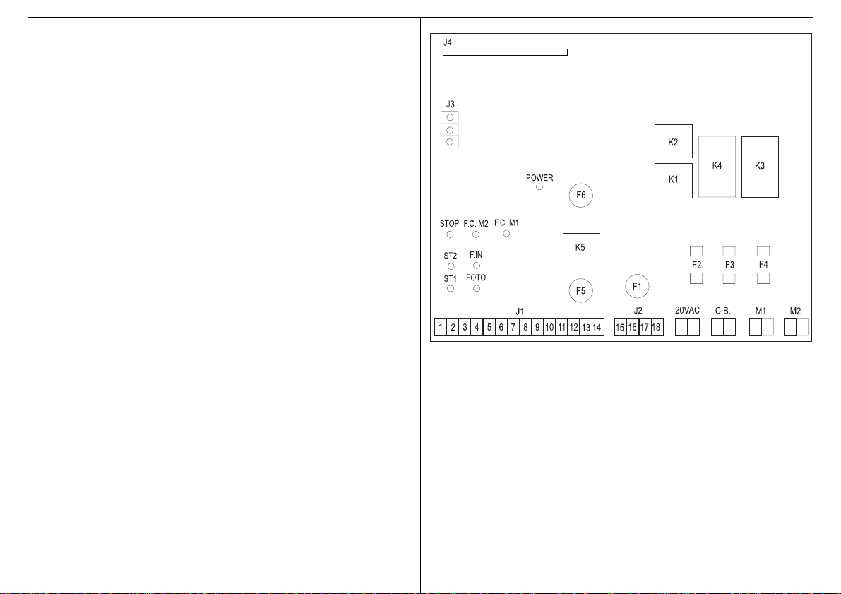
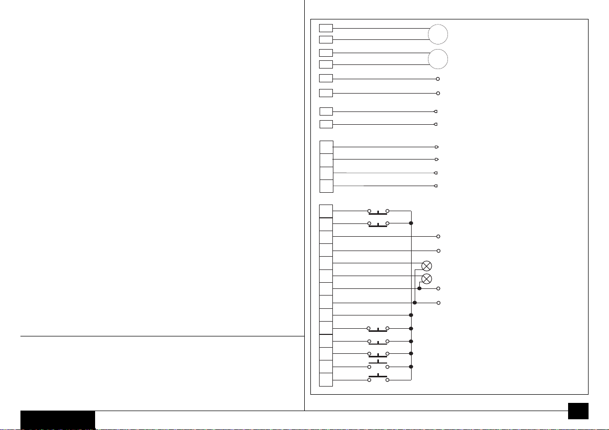
Ingresso finecorsa 1 – MORSETTO 13/6 DELLA MORSETTIERA J1. Collegamento
per l’eventuale finecorsa elettromeccanico (o equivalente) presente sull’operatore nr. 1.
Permette l’attivazione, da parte della centralina di controllo, della fase di rallentamento
nell’ultimo arco di corsa sia in apertura che in chiusura.
Ingresso fine corsa 2 – MORSETTO 14/6 DELLA MORSETTIERA J1. Collegamento
per l’eventuale finecorsa elettromeccanico (o equivalente) presente sull’operatore nr. 2.
Permette l’attivazione, da parte della centralina di controllo, della fase di rallentamento
nell’ultimo arco di corsa sia in apertura che in chiusura.
Uscita elettroserratura – MORSETTO 12/11 DELLA MORSETTIERA J1.Uscita a 12
VAC con carico massimo di 15 W, che comanda l’elettroserratura per circa 1,5 secondi
nella fase di apertura.
Uscita lampada spia – MORSETTO 8/9 DELLA MORSETTIERA J1.Uscita a 24VDC
con carico massimo di 3 W, che comanda la lampada spia di segnalazione dello stato
del cancello.Lampada spenta:cancello chiuso, lampada accesa fissa: cancello aperto
o in fase di apertura, lampada lampeggiante:cancello in fase di chiusura.
Uscita lampeggiatore a LED – MORSETTO 7/10 DELLA MORSETTIERA J1.Uscita
a 24V, che comanda il lampeggiatore a led.
Quest’uscita comanda il lampeggiatore con un’alimentazione pulsante con frequenza
1HZ: accensione della luce per 0,5 secondi e spegnimento per 0,5 secondi. In caso di
abilitazionedelprelampeggio, questauscitaviene attivata3secondi primadel comando
del movimento delle ante sia in apertura che in chiusura.
NOTA - Utilizzare esclusivamente lampeggiatori a LED serie ET Aprimatic, se si
vuole evitare la rottura dell’uscita e il conseguente malfunzionamento
dell’intero sistema.
Uscita motori – MORSETTIERE MOTORI.L’apparecchiaturaT4professionaledispone
didue uscite per motori indipendenti, motore1 e motore 2.L’uscita del motore 1 è quella
che permette di selezionare il ritardo d’anta in chiusura tramite il PROGRAMMATORE.
Incasodi utilizzodell’ingresso anta singola si otterrà lasola partenzadell’anta collegata
all’uscita del motore 1;se durante questa fase si invia un impulso di START si otterrà la
partenza della seconda anta.
NOTA – In caso di utilizzo di questa apparecchiatura in automazioni dotate di una sola
anta, il motore deve necessariamente essere collegato all’uscita motore 1.
NOTA – In caso di utilizzoadantasingola,nonconnettere l’ingresso del finecorsamotore
2 al morsetto 14.

Uscita caricabatteria - MORSETTIERA C.B. Ai morsetti C.B.dell’apparecchiaturaT4-
P è possibile collegare una scheda ausiliaria (da alloggiarsi nello stesso contenitore
plastico dell’apparecchiatura) per il controllo di un gruppo di batterie di emergenza le
quali,in mancanzaditensionedi rete,consentono di effettuareunamanovradi emergenza
di apertura/chiusura.
ATTENZIONE - Rispettare la polarità indicata per il collegamento della scheda
addizionale ai morsetti caricabatteria.
NOTA - Utilizzare esclusivamenteil gruppodibatteriediemergenzafornitoda Aprimatic.
5. COLLEGAMENTO SCHEDE OPZIONALI
5.1 SCHEDA ES PER SEMAFORO UNIDIREZIONALE
Start semaforo 1
Semaforo 2
Semaforo 1
Start semaforo 2
MorsettieraT4Prof
Verde
Rosso
Verde
Rosso
Modalità di collegamento
1. Togliere l’alimentazione elettrica
all’apparecchiatura.
2. Inserire la scheda nel connettore J4
rispettando la configurazione della
piedinatura.
3. Collegare i semafori alla
morsettiera della scheda ES come
indicato in figura.
4. Collegare un pulsante con contatto
NA ai morsetti 1 e 6 della scheda
T4Prof.Questo pulsante
comanderà il semaforo 1.
5. Collegare un pulsante con contatto
NA al morsetti 7 e 8 della scheda
ES.Questo pulsante comanderà il
semaforo 2.

5
ENGLISH
Safety recommendations
• The manufacturer’s instructions must be strictly observed.
• The installer must check the installation and the correct functioning of the device.
• The product must not be used incorrectly or for purposes that are not envisaged.
• The product must not be tampered with or modified in any way.
• Always use original spare parts.
• Cordon off the working area to prevent the access of unauthorised persons.
• Ensure that the working area is clear of obstacles and the floor is not slippery.
• All equipment used must be in good working condition.
• The working area must be sufficiently well lit and free of health hazards.
• Unauthorised persons must not enter the working area.
• The working area must not be left unattended.
Purpose of the manual
This manual was drawn up by the manufacturer and is an integral part of the product.
The information it contains is addressed to expert operators that carry out the installation and
extraordinary maintenance. They must have the specific qualifications and training to carry out
the operations assigned to them correctly and under the maximum safety conditions. Strict
observation of the instructions contained in the manual will ensure safety, optimum operation and
prolonged functioning of the product.To avoid incorrect manoeuvres and the consequent risk of
accidents, it is important to read this manual carefully, strictly observing the instructions given.
Application range
Equipment for Aprimatic swing gate operators.
Contents
1. DESCRIPTION ................................................................................................................. 6
1.1 Block diagram of equipment................................................................................... 6
2. INSTALLATION ................................................................................................................. 6
2.1 Preparation ............................................................................................................ 6
2.2 Assembly................................................................................................................ 6
2.3 Electrical connections ............................................................................................ 6
3. START-UP ......................................................................................................................... 6
3.1 Functioning tests .................................................................................................... 6
3.2 Adjustments ........................................................................................................... 6
3.3 Operating programming ......................................................................................... 7
3.4 Settings/selections ................................................................................................. 7
4. FUNCTIONING CONTROL .............................................................................................. 7
4.1 Checking functioning of the external devices ......................................................... 7
5. OPTIONAL CARD CONNECTION ................................................................................... 8
5.1 ES card for one-way traffic light ............................................................................. 8
Aprimatic S.p.A. • Zona Industriale Fossatone
40060 Villa Fontana • Medicina • Bologna (ITALY)
tel.+39-051.6979511 • fax +39-051.6930396

1. DESCRIPTION
Equipment supplied with a mains power supply of 230VAC 50Hz, dedicated to piloting and control
of swing gates driven by electro-mechanical operators supplied with power at 24 VDC. Stand-by
consumption: 15 W. Maximum power of the operators/motors:520 Watt.
All functioning mode selection, parameter setting and function setting is carried out using a device
known as the PROGRAMMER, supplied exclusively to qualified APRIMATIC installers.
1.1 BLOCK DIAGRAM OF EQUIPMENT
J1 Signal terminal board
J2 Power terminal board
J3 Radio receiver plug-in connector
J4 Connector for additional cards
CB Battery charger connection terminal
board
M1 Motor 1 connection terminals
M2 Motor 2 connection terminals
20VAC Secondary transformer terminal
F1 Mains 3.15A fuse
F2 20 VAC low voltage 16A fuse
F3 Motor 1 8A fuse
F4 Motor 2 8A fuse
F5 Electric lock 2A fuse
The connector for the programmer is on the CPU card.
2. INSTALLATION
CAUTION - The product may only be installed by the qualified technical personnel of the
assistance and/or assembly service.
CAUTION - The electrical system must comply with current standards in the country where the
unit is installed.
CAUTION - Always disconnect the power supply before opening the container.
2.1 PREPARATION
Before assemblingthe equipment, prepare the tools required forwall-mountingandfortheelectrical
connections.The following are also required:
1. 6 mm diameter expansions plugs
2. Skintop type PG16 cable clamps
3. a multipole switch with minimum contact opening of 3 mm
4. an emergency push-button
5. approved cables for external use with cross-section of 0.75 minimum and 2.5 mm²
F6 Logic and accessories 2A fuse
ST1 Start input LED
ST2 Pedestrian Start/Close input LED
STOP Stop input LED
FOTO Standard photocell input LED
F.IN Additional photocell input LED
F.C.M1 Motor 1 limit switch input LED
F.C.M2 Motor 2 limit switch input LED
POWER 24 VDC power supply present LED
K1 Motor 1 ON/OFF relay
K2 Motor 2 ON/OFF relay
K3 Motor 1 direction relay
K4 Motor 2 direction relay
K5 Electric lock relay
Opening delay
20VAC – From the secondary transformer
To the primary transformer
230V - 50 Hz
N
Ph
N
Ph
T4Prof.EPS
J2
J1
15
+
+
+
+
17
16
-
-
-
-
18
M2
M1
Closing delay
From the battery charger circuit

ENGLISH
2.2 ASSEMBLY
You do not need to drill holes to fit the equipment.
1. Assemblethe equipment at a heightofat least 30 cm, using theholesin the plastic container.
2. Insert the connection cable, using the pre-marked holes on the bottom of the container and
the cable clamp indicated.
3. Install the multipole switch upstream of the equipment.
4. Install an emergency push-button in a position which allows you to see the operator system
and which ensures that the switch completely cuts off the power supply to the operator.
5. Use the 2.5 mm² minimum cross-section cable to connect the mains power supply to the
motor; for connections longer than 6 m, use cable with a cross-section of 4 mm². Use the
0.75 mm² cross-section cable for the other 24 VDC devices.
2.3 ELECTRICAL CONNECTIONS
CAUTION - Before making the connections, turn OFF the mains power supply.
CAUTION - Do NOT use intercom or telephone cable.
Make the electrical connections as indicated in the diagram.
NOTE - As envisaged by current standards, separately strap the connection cable for the
controls (terminals from 1 to 14) and the power cable (terminal boards M1 and M2).
3 START-UP
After making the connections as indicated and carefully checking the electrical connections, turn
the mains power supply ON and check that the system is operating correctly as specified below.
3.1 FUNCTIONING TESTS
After making the connections, check the operator system:when you press the start push-button,
the gate must open. If the gate closes, invert the motor connections.
3.2 ADJUSTMENTS
Use the programmer to adjust the operator work time and mode.
CAUTION - The pins on the connector must be plugged in correctly; if the connector is difficult to
insert, check that it is the right way round.
NOTE - The number indicated in front of the description for each parameter is the number
which indicates the function in operation.The values are shown on the PROGRAMMER
display (2 left-side digits).
Thesquare brackets contain the settingrangeof thePROGRAMMER (2right-side digits).
10 – WING OPENING DELAY (0 – 20 s) [Range: 0 – 20]
Delays opening of one wing compared to the other wing controlled by the same operator.
11 – WING CLOSING DELAY (0 – 20 s) [Range: 0 - 20]
Delays closing of one wing compared to the other wing controlled by the same operator.
6
12 - APPROACH/SLOW-DOWN SPEED [Range: 0 – 20]
Thegateslowsdownwhen it reachesthelimitswitch (duringopeningor closing).This prevents
violent knocking of the gates. Can only be enabled for operators with limit switches.
13 – PAUSE TIME (2 – 180 s) [Range: 1 – 90]
In the automatic operating mode, this function sets the pause time when the wings are open.
14 – WORKTIME (2 – 180 s) [Range: 1 – 90]
Adjusts the operator work time, which is especially useful for operators without limit switches.
15 – BRAKE ENABLING DELAY (0 – 2 s) [Range: 0 – 20]
This function is only used for sliding gates.
16 – ANTI-CRUSH DEVICE ADJUSTMENT [Range: 0 – 99]
Adjusts the sensitivity of the system which recognises obstacles, preventing movement of
the gates.
CAUTION - Set the parameter to 99 for the maximum operator thrust force.
17 – PARTIAL OPENING SPAN (0 – 32 s) [Range: 0 – 32]
This function is only used for sliding gates.
T4PROFMO.EPS
Motor 2 limit switch
Electric lock
Motor 1 limit switch
LED flashing unit
Max. 3W warning light
Accessory power supply
Shared inputs
Opening safety device photocell
Photocell
Stop
Pedestrian start/Close
Start
J1
4
2
3
5
1
9
12
13
14
7
10
8
11
6
+
-
-
+
-
+
N.B. All the N.C.safety contacts (Stop, photocells and motor limit switches) must be jumpered
if they are not used.
CAUTION!
Strap the low voltage cables together near terminal board J1. Strap the power cables together
near terminal board J2.

3.3 OPERATING PROGRAMMING
NOTE - The numbers indicated in square brackets indicate the operating mode and are shown on
the PROGRAMMER display: the number 25 (2 left-side digits) indicates the OPERATING
PROGRAM, the 2 right-side numbers indicate the type of operating mode currently in use.
AUTOMATIC [25 – 00]
When you select this type of operating and a start pulse is given, the gate opens as far as the limit
switch and stays open for the pre-set pause time and then closes automatically.
• Astart pulse givenduring closing reversesthe direction of thegate (in other words,thegate re-opens).
• A start pulse given during opening is ignored; a pulse given during the pause restarts the pause time.
SPECIAL AUTOMATIC [25 – 01]
When you select this type of operating and a start pulse is given, the gate opens as far as the limit
switch and stays open for the pre-set pause time and then closes automatically.
• Astart pulse givenduring closing reversesthe direction of thegate (in other words,thegate re-opens).
• A start pulse given during opening is ignored; a pulse given during the pause restarts the pause time.
• If the photocells are triggered, there is a pause of 3 seconds and the gate then closes.
SUPER AUTOMATIC [25 – 02]
When you select this type of operating and a start pulse is given, the gate opens as far as the limit
switch and stays open for the pre-set pause time and then closes automatically.
Astart pulsegivenduring anystage reverses the direction:youcan closethegate with a command.
• A pulse given during the pause triggers pre-flashing and subsequent closing of the gate.
NOTE - in the Automatic and Super Automatic modes, the photocells can be set as in function 43.
Photocell setting has PRIORITY over the operating logic.
DIAGNOSTICS [25 – 03]
The diagnostics routine is used to check the correct functioning of all the outputs and inputs, as follows.
The microprocessor enables all the outputs in sequence (motor 1 ON/OFF relay, motor 2 ON/
OFF relay, electric lock relay, flashing unit, warning lights) and then waits until the inputs are
enabled; if no input has been enabled within 10 seconds of the end of the output test routine, the
output enabling sequence is repeated.
If, on the other hand, an input is enabled and the diagnostics is OK, the microprocessor commands
a number of complete flashing cycles (0.5 s ON and 0.5 s OFF) equal to the progressive number for
the input enabled (start=1, start pedestrain/close=2, stop=3, standard photocell=4, additional
photocell=5, motor 1 limit switch=6, motor 2 limit switch =7).
OPEN/CLOSE SEMIAUTOMATIC [25 – 04]
When you select this type of operating, terminal number 2 of the J1 terminal board assumes the
Closefunction.Inthismode,youcanhaveseparateinputsfor opening (START)andclosing (CLOSE).
Once opened, the gate remains open until the “CLOSE” command is given.
• A start pulse during closing re-opens the gate.
• A close pulse during opening closes the gate.
THIS FUNCTION DOES NOT PERMIT PEDESTRIAN OPENING.
36 – CLOSING PRE-FLASHING (ON=1/OFF=0)
Light flashing for 3 seconds before the motors (and the warning light) start during closing.
37 – RELEASE STROKE (swing gates only) (ON=1/OFF=0)
Before opening, with the maximum force, the operator commands a brief closing movement
to facilitate the release of the electric lock.
38 – REVERSE AT END OF CYCLE (ON=1/OFF=0)
This function is used for up-and-over garage doors only.
39 – AUTOMATIC START WITH ADDITIONAL SAFETY DEVICE TRIGGERED (OFF=0)
Used to complete the automatic cycle when the additional safety device has been disabled.
This function prevents the gate from opening or closing when the space require for gate
opening or closing (not covered by the standard photocell, terminal 5/6) is blocked by an
obstacle (signalled by additional photocells).
TO USETHIS FUNCTION,YOU MUST CONNECT APAIR OF ADDITIONAL PHOTOCELLS
TO TERMINALS 5/6 ON THE J1TERMINAL BOARD.
39 - MANUAL START WITH ADDITIONAL SAFETY DEVICE TRIGGERED (ON=1)
Operatesasabovewiththedifference that, when the photocell has been cleared,theoperator
must give a new pulse (START).
TO USETHIS FUNCTION,YOU MUST CONNECT APAIR OF ADDITIONAL PHOTOCELLS
TO TERMINALS 5/6 ON THE J1TERMINAL BOARD.
40 – SLOW-DOWN BASE
Thisfunctionisonly used foroperatorscommanded bymotors with a powersupply of 220VAC.
41 – ANTI-CRUSH DEVICE MANAGEMENT
If you set the PROGRAMMER to ON (1), the anti-crush device functions as an immediate
STOP when there is an obstacle and the gate only starts again when a START pulse is
given.
In the OFF (0) position, the anti-crush device functions as a thrust limiter until the end of the
work time; the gate only starts again when a START pulse is given.
The parameter is pre-set to ON (1).
42 – STOP WITH ADDITIONAL SAFETY PHOTOCELL TRIGGERED (0)
When the additional opening safety photocell is triggered (terminal 5/6 on the J1 terminal
board), the gate STOPS immediately.
When the safety photocell is cleared, the gate starts to open again after 0.5 seconds.
To obtain this function, you must connect a pair of additional photocells to terminals
5/6 on the J1 terminal board.
42 – STOP WITH ADDITIONAL SAFETY PHOTOCELLTRIGGERED + SLIGHT REVERSE (1)
Asabove theonly differencebeing that, when theobstacle is detected, theoperatorreverses
the direction for a brief period and then stops.
To obtain this function, you must connect a pair of additional photocells to terminals
5/6 on the J1 terminal board.

ENGLISH
SEMIAUTOMATIC WITH STOP (step-by-step) [25 – 05]
When you select this type of operating and a start pulse is given, the gate opens as far as the limit switch.
• The remains open, until a new command is given.
• A start pulse closes the gate (close command).
• A start pulse during closing and/or opening stops the gate allowing partial opening.
SEMIAUTOMATIC WITH REVERSE [25 – 06]
This operating mode is virtually identical to the automatic mode.There is one difference: when a
start pulse is given during closing, the gate is re-opened.
• A START pulse during opening STOPS the gate.
DEAD MAN (holding down the push-button) [25 – 07]
When you select this type of operating, terminal number 2 of the J1 terminal board assumes the
pedestrian start function. In this mode, an operator must be present to open and close the gate.
To open the gate, press and hold down the start button.Release it to stop the gates.To close the
gate, press and hold down the close button; if the photocells are triggered, the gates are blocked.
At this point, the operator must release the button and decide how to proceed:he can press either
open or close.
The same occurs if the open and close buttons are pressed at the same time.
TRAFFIC LIGHTS [25 – 08]
To use this function, the equipment must have an optional “traffic light” card, which must be
connected to the J4 connector to power the four lights (two red and two green) with a power
supply of 220 VAC. This operating mode is identical to Standard Automatic, with the addition of
the traffic light functions described below.You must also connect two Start push-buttons with a
NO contact between terminals 1 and 6 of theT4Prof equipment and between terminals 7 and 8 of
the optional card.In the “Traffic Lights”mode, when the system is in stand-by, the two traffic lights
have a steady red light.When one of the two Start inputs is enabled, the corresponding traffic light
starts to flash alternately red and green; when the gate is open, the light remains green until 6
seconds before the gate starts to close. It then flashes alternately red and green for 3 seconds
and turns red again when the gate is fully closed.
If the two Start buttons are pressed at the same time, the device will automatically give priority to
the one which was pressed first. Once the cycle has started, all start pulses are ignored.
NOTE - Thisoperatingmode disablesthe stop button, the additional safetydevice,the pedestrian
start, pre-flashing, the electric lock and the release stroke.
3.4 SETTINGS/SELECTIONS
NOTE -The number indicated in front of the description for each parameter is the number which
indicates the function in operation.The values are shown on the PROGRAMMER display
(2 left-side digits).
The brackets indicate the selections possible: ON or OFF (2 right-side digits)
35 – OPENING PRE-FLASHING (ON=1/OFF=0)
Light flashing for 3 seconds before the motors (and the warning light) start during opening.
43 – PHOTOCELLS: STANDARD OR WITH RESET.
When the photocells are triggered, you can vary their function as follows:
PROGRAMMER OFF (0) the triggered photocells start the pause time count (open gate
pause)
PROGRAMMER ON (1) the triggered photocells cancel the open gate pause time and,
once cleared, after pre-flashing for 3 seconds, close the gate.
44 – ANTI-CRUSH DEVICE ENABLING (ON=1/OFF=0)
This function is used to enable or disable the electronic anti-crush device function.
OFF: with hydraulic operators only.
45 – NO START WHEN STANDARD SAFETY DEVICE IS TRIGGERED (start=0/no start=1)
This function is used to enable or disable an additional function and operates as follows:
When the closing photocells (terminals 18/19 on the CN3 terminal board) are triggered
with the gate is closed and at a standstill, and the safety device is set at 0, a START pulse
opens the gates normally; if the photocells are triggered when the gate is closed and the
safety device is set at 1, the equipment does not accept any type of START pulse and
blocks gate movement until the photocells are cleared.
4. FUNCTIONING CONTROL
After programming the equipment, check the external devices connected to the card.
4.1 CHECKING FUNCTIONING OF THE EXTERNAL DEVICES
Start input – TERMINAL 1/6 ON THE J1 TERMINAL BOARD. N.O. contact which sends the
start pulse to the operator
Stop input – TERMINAL 3/6 ON THE J1 TERMINAL BOARD. N.C. safety contact which has
priority over all states and all functions. If there is a STOP pulse, the operator stops the gate in
position and only starts again after START is pressed, which closes the gate. When the STOP
input is enabled, the equipment ignores all the commands.
Photocell input –TERMINAL 4/6 ON THE J1TERMINAL BOARD. N.C. safety contact which is
only enabled during closing. If the photocell is triggered, the gate stops for 1 second and then
reopens until the end of the work time.When the gate is open and the photocells are triggered,
the gate cannot close.
Pedestrian start input –TERMINAL 2/6 ONTHE J1TERMINAL BOARD. N.O.contact.Use this
button to open/close one wing only (pedestrian opening). This single wing will operate in the
mode set for the equipment (AUTOMATIC, SPECIAL AUTOMATIC, SUPER AUTOMATIC,
SEMIAUTOMATICWITH STOP,SEMIAUTOMATICWITH REVERSE).A STARTpulse givenduring
single wing opening moves the second wing.The SINGLE WING START pulse is ignored for the
entire gate movement when opening was commanded with a START pulse.
7

Opening safety device input – TERMINAL 5/6 ON THE J1 TERMINAL BOARD. N.C. type
contact.This safety device input is enabled during both opening and closing.When the input is
enabled, the gates are stopped in position while, when disabled, the gates start moving again in
the same direction as before, after a pause of 1 second. This function can be used to protect
areas where there is a danger of crushing.
Close input –TERMINAL 2/6 ONTHE J1TERMINAL BOARD.N.O.contact.When the equipment
is set to OPEN/CLOSE SEMI AUTOMATIC or DEAD MAN, press this button to close the gate.
Limit switch 1 input –TERMINAL 13/6 ONTHE J1TERMINAL BOARD. Connection for electro-
mechanical (or equivalent) limit switch on operator 1.Used by the control cabinet to enable the
slow-down stage for the final part of the opening and closing strokes.
Limit switch 2 input –TERMINAL 14/6 ONTHE J1TERMINAL BOARD. Connection for electro-
mechanical (or equivalent) limit switch on operator 2.Used by the control cabinet to enable the
slow-down stage for the final part of the opening and closing strokes
Electric lock output – TERMINAL 12/11 ON THE J1 TERMINAL BOARD. 12 VAC output with
maximum load of 15 W, which commands the electric lock for approximately 1.5 seconds during
opening.
Warning light output – TERMINAL 8/9 ON THE J1 TERMINAL BOARD. 24 VDC output with
maximum load of 3 W, which commands the gate state warning light. Light OFF: gate closed.
Steady light: gate open or opening. Flashing light: gate closing.
LED flashing output– TERMINAL 7/10 ON THE J1 TERMINAL BOARD. 24V output, which
commands flashing of the LED’s.
This output commands the LED’s with a pulsating power supply with frequency of 1HZ: light ON
for 0.5 seconds and OFF for 0.5 seconds. If pre-flashing is enabled, this output is enabled 3
seconds before the gates are moved during both opening and closing.
NOTE - Only use Aprimatic ET series LED’s to prevent breakage of the output and
consequent malfunctioning of the entire system.
Motor output –MOTORTERMINAL BOARDS.The T4 professional equipment has two outputs
for independent motors: motor 1 and motor 2.The output for motor 1 is used to select the wing
closing delay using the PROGRAMMER.If you use the single wing input, only the gate connected
to the output for motor 1 can start; if a START pulse is given during this stage, the second gate
starts.
NOTE – If you use this equipment in operators used for only one wing, the motor must be
connected to the output for motor 1.
NOTE – If you use only one wing, do NOT connect the input for the motor 2 limit switch to
terminal 14.
Battery charger output- C.B.TERMINAL BOARD.You can connect an auxiliary card to the C.B.
terminals in the T4-P equipment (in the same plastic container as the equipment) to control an
emergency battery unit which, in the event of a power failure, is used for emergency gate opening/
closing.
CAUTION - Respect the polarity indicated when connecting the additional card to the battery
charger terminals.
NOTE - Only use the emergency battery unit supplied by Aprimatic.
5. CONNECTING OPTIONAL CARDS
5.1 ES CARD FOR ONE-WAY TRAFFIC LIGHT
Traffic light 1 start
Traffic light 2
Traffic light 1
Traffic light 2 start
T4Prof terminal board
Green
Red
Green
Red
Connection
1. Turn OFF the power supply to the
equipment.
2. Insert the card in the J4 connector,
respecting the pin configuration.
4. Connect a push-button with NO
contact to terminals 1 and 6 of the
T4Prof card.This button is used for
traffic light 1.
3. Connect the traffic lights to the
terminal board on the ES card as
illustrated in the diagram.
5. Connect a push-button with NO contact
to terminals 7 and 8 of the ES card.
This button is used for traffic light 2.

8
FRANÇAIS
Normes de sécurité
• Effectuer les interventions de la façon spécifiée par le fabricant.
• L’installateur doit vérifier l’installation et le bon fonctionnement du dispositif.
• Ne pas utiliser le produit dans des buts différents de ceux qui ont été établis.
• Ne pas fausser ou modifier le produit.
• Utiliser les pièces détachées d’origine.
• Délimiterla zonedetravaildefaçonàeninterdire l’accèsàtoutespersonnes étrangères
auservice.
• La zone de travail ne doit pas présenter d’obstacles et sa surface ne doit pas être
glissante.
• Utiliser un outillage en bon état.
• Travailler toujours dans un endroit bien éclairé et ne présentant aucun risque pour la
santé.
• Le passage de personnes étrangères au service est impérativement interdit dans la
zone de travail.
• Ne jamais abandonner la zone de travail.
But du manuel
Ce manuel a été rédigé par le fabricant et fait partie intégrante du produit.
Les informations qui y sont contenues s’adressent aux opérateurs spécialisés qui
effectuent l’installation et les interventions d’entretien extraordinaire. Ceux-ci doivent
posséder des compétences spécifiques pour effectuer, correctement et dans des
conditionsde sécurité,les interventionsqui leur incombent.L’observationconstantedes
instructions contenuesdanscemanuelgarantit la sécuritédespersonnes,une économie
de service et une plus longue durée de fonctionnement du produit. Pour éviter toutes
fausses manœuvres et donc tous risques d’accidents, lire attentivement ce manuel et
respecter scrupuleusement les informations qui y sont contenues.
Champ dapplication
Bloc électronique des actionneurs pour portails Aprimatic.
Sommaire
1. DESCRIPTION ........................................................................................... 9
1.1 Schéma fonctionnel ........................................................................... 9
2. INSTALLATION ........................................................................................... 9
2.1 Préparation ........................................................................................ 9
2.2 Montage ............................................................................................ 9
2.3 Raccordements électriques ............................................................... 9
3. MISE EN SERVICE
3.1 Essais .............................................................................................. 10
3.2 Réglages ......................................................................................... 10
3.3 Programmation ................................................................................ 10
3.4 Mises au point/programmation/sélections ........................................ 11
4. CONTROLE .............................................................................................. 11
4.1 Vérification des dispositifs externes ................................................. 11
5. RACCORDEMENT DES CARTES OPTIONNELLES................................ 12
5.1 Carte ES pour feu de signalisation unidirectionnel........................... 12
Aprimatic S.p.A. • Zona Industriale Fossatone
40060 Villa Fontana • Medicina • Bologna (ITALY)
tel.+39-051.6979511 • fax +39-051.6930396

1. DESCRIPTION
Ce bloc électronique, alimenté à 230 Vca 50 Hz, a pour fonction de commander et de
contrôler la fermeture et l’ouverture de portails motorisés par des actionneurs
électromécaniquesalimentésà24Vcc.Consommationenstand-by15Watts.Puissance
maximale des actionneurs/moteurs 520Watts maxi.
Un dispositif, dit PROGRAMMATEUR, permet de choisir le mode de fonctionnement,
desélectionner les paramètreset lesfonctions;cedispositifestdisponibleexclusivement
auprès des installateurs qualifiés APRIMATIC.
1.1 SCHEMA FONCTIONNEL
J1 Borniersignaux
J2 Bornier puissance
J3 Connecteurdu radiorécepteur
J4 Connecteurpour cartes supplémentaires
CB Bornier de raccordement de chargeur
debatteries
M1 Bornes de raccordement moteur 1
M2 Bornes de raccordement moteur 2
20Vca Borne secondairetransformateur
F1 Fusible 3,15A secteur
F2 Fusible 16A basse tension 20 Vca
F3 Fusible 8A moteur 1
F4 Fusible 8A moteur 2
F5 Fusible 2A verrouillageélectromécanique
F6 Fusible 2A logique etaccessoires
Le connecteur du programmateur
est monté sur la carte CPU
2. INSTALLATION
ATTENTION - Leblocélectronique nepeutêtreinstalléquepardesinstallateursagréés
et/ou des techniciens qualifiés du service d’assistance Aprimatic.
ATTENTION - L’installation électrique doit être réalisée conformément à la
réglementation en vigueur dans le pays d’installation.
ATTENTION - Avant d’ouvrir le boîtier, coupez le courant.
ST1 Led entrée marche
ST2 Led entrée marche ouverture
piétonne/fermer
STOP Led entrée arrêt
FOTO Led entrée cellule
photoélectrique standard
F.IN Led entrée cellule
photoélectriquesupplémentaire
F.C.M1 Led entrée fin de course moteur 1
F.C.M2 Led entrée fin de course moteur 2
POWER Ledalimentation24Vcc présente
K1 Relaisactivationmoteur 1
K2 Relaisactivationmoteur 2
K3 Relais direction moteur 2
K4 Relais direction moteur 1
K5 Relaisverrouillage
électromécanique
T4Prof.EPS

FRANÇAIS 9
2.1 PREPARATION
Avant de procéder au montage du bloc électronique, préparez tous les outils qui vous
seront utiles pour la pose et les raccordements électriques. Vous devez également
disposer du matériel suivant :
1. chevilles à expansion Ø 6 mm
2. serre-câbles PG16 du type skintop
3. interrupteur omnipolaire avec une ouverture des contacts de min.3 mm.
4. bouton d’arrêt d’urgence
5. câbles pour usage externe, approuvés, de 0,75 min.de Ø et de 2,5 mm² de section.
2.2 MONTAGE
Pour fixer le bloc électronique, vous ne devez pratiquer aucun perçage.
1. Fixez le bloc électronique à au moins 30 cm de haut, en vous servant des trous de
fixation existant sur le boîtier en plastique.
2. Faites passer les câbles de raccord par les trous existant sur le fond du boîtier et les
serre-câblesindiqués.
3. Installez un interrupteur omnipolaire en amont du bloc électronique.
4. Installez un bouton d’arrêt d’urgence en mesure d’interrompre complètement
l’alimentationenénergieélectrique del’équipementetdansune position qui permette
à l’usager de voir la motorisation.
5. Utilisez des câbles de 2,5 mm² mini de section pour raccorder l’alimentation des
moteurs à la centrale de commande.Pour les raccordements supérieurs à 6 m, il est
recommandé d’utiliser des câbles de 4 mm² de section.Utilisez des câbles de 0,75 mm²
pour les dispositifs à 24 Vcc.
2.3 RACCORDEMENTS ELECTRIQUES
ATTENTION - Avant de procéderau raccordement, coupez l’alimentation électriquedu
réseau.
ATTENTION - N’utilisez pas de câbles pour téléphones ou parlophones.
Effectuez les raccordements électriques comme l’indique le schéma ci-contre.
NOTE - Comme le prévoit la réglementation en vigueur,liez les câbles de raccord
entre eux (de la borne 1 à la 14) et les câbles de puissance entre eux
(borniers M1 et M2)
T4PROFMO.EPS
N.B. Tous les contacts N.F.de sécurité(Arrêt,cellulesphotoélectriquesetfinsdecourse
moteurs) doivent être pontés s’ils ne sont pas utilisés.
ATTENTION !
Liezfermement entre eux les câblesà basse tension à proximitédu bornier J1.Puis liez
entre eux les câbles de puissance à proximité du bornier J2.
Retard en ouverture
20 Vca – Du secondaire du transformateur
Au primaire du transformateur
230 V - 50 Hz
N
P
N
P
Fin de course moteur 2
Serrure électrique
Fin de course moteur 1
Clignotant à LED
Lampe témoin 3 W maxi
Alimentation accessoires
Commun entrées
Cellule photoélectrique sécurité en ouverture
Cellule photoélectrique
Arrêt
Marche piétonne / Fermer
Marche
J2
J1
4
15
+
+
+
+
17
2
3
5
16
-
-
-
-
1
9
12
13
14
7
10
8
11
6
18
M2
M1
+
-
-
+
-
+
Retard en fermeture
Du circuit du chargeur de
batteries

3 MISE EN SERVICE
Aprèsle raccordement et après avoirsoigneusement vérifiéles connexionsélectriques,
mettez l’installation sous tension et vérifiez si elle fonctionne bien en suivant les
instructions ci-dessous.
3.1 ESSAIS
A ce stade, il faut contrôler le fonctionnement de la motorisation.Vérifiez si, en pressant
leboutondemarche,leportail s’ouvre ;sileportailseferme, inversez les raccordements
des moteurs.
3.2 REGLAGES
Le programmateur permet de régler les temps et modes de fonctionnement du
portail.
ATTENTION - Le connecteur est polarisé et doit être branché dans un seul sens.Si le
branchement a été forcé, vérifiez s’il a été effectué du bon côté.
NOTE - Le numéro qui précède la description d’un paramètre correspond au numéro
dela fonctioncourante.L’afficheur du PROGRAMMATEUR signaleles valeurs
(2 chiffres à gauche).
La plage admissible par le PROGRAMMATEUR est entre crochets (2 chiffres
à droite).
10 – RETARD DU VANTAIL EN OUVERTURE (0 – 20 s) [Plage : 0 – 20]
Retarde le mouvement en ouverture d’un vantail du portail par rapport à l’autre.
11 – RETARD DU VANTAIL EN FERMETURE (0 – 20 s) [Plage : 0 - 20]
Retarde le mouvement de fermeture d’un vantail du portail par rapport à l’autre.
12 - VITESSE D’APPROCHE/RALENTISSEMENT [Plage :0 – 20]
En fin de course (ouverture ou fermeture), le mouvement ralentit. Evite le
claquement des vantaux.Uniquement sur actionneurs équipés de fins de course.
13 –TEMPS DE PAUSE (2 – 180 s) [Plage :1 – 90]
Dans le mode automatique, le temps de pause règle le temps d’arrêt du vantail ou
des vantaux ouvert(s).
14 –TEMPS DETRAVAIL (2 – 180 s) [Plage: 1 – 90]
Règlele temps de travaildes actionneurs, utile spécialement sur actionneurssans
fin de course.
15 – RETARD ACTIVATION DU FREIN (0 – 2 s) [Plage: 0 – 20]
Sur coulissants exclusivement.
NOTE - Dans les modes de fonctionnement «automatique» et «automatique super»,
lescellulesphotoélectriques peuventêtre programmées comme pour lafonction
43. La programmation d’une cellule photoélectrique est PRIORITAIRE sur la
logique de fonctionnement.
DIAGNOSTIC [25 – 03]
Lediagnostic permet de vérifier le bon fonctionnementde toutes les sorties et detoutes
les entrées en procédant comme suit.
Le microprocesseur active en séquence toutes les sorties (relais activation moteur 1,
relais activation moteur 2, relais direction moteur 1, relais direction moteur 2, relais
verrouillage électromécanique, clignotant, lampe témoin) et attend ensuite l’activation
de toutes les entrées ; si 10 secondes après le test des sorties, aucune entrée n’est
activée, le microprocesseur répète la séquence d’activation des sorties.
Si, au contraire, une entrée est activée, dans le cas d’un diagnostic OK, le
microprocesseur commande un nombre de cycles complets de clignotement (0,5 s ON
et0,5 s OFF),égalaunombreprogressif de l’entréeactivée(marche=1,marche ouverture
piétonne/fermer=2, arrêt=3, cellule photoélectrique standard=4, cellulephotoélectrique
supplémentaire=5, fin de course moteur 1=6, fin de course moteur 2=7).
SEMI-AUTOMATIQUE OUVRIR/FERMER [25 – 04]
En semi-automatique Ouvrir/Fermer, la borne 2 du bornier J1 prend la fonction de
commande “Fermer”. De cette façon, on peut avoir les entrées séparées par ouverture
(OUVRIR) et fermeture (FERMER).
Une fois ouvert, le portail est en pause infinie et attend une commande “Fermer”.
• Une impulsion de marche “Ouvrir” en phase de fermeture provoque la réouverture.
• Une impulsion de marche “Fermer” en phase d’ouverture provoque la fermeture.
CETTE FONCTION NE PERMET PAS D’OUVRIR LE PORTAIL POUR UNE
OUVERTUREPIETONNE.
SEMI-AUTOMATIQUE AVEC ARRET (pas à pas) [25 – 05]
En semi-automatique avec arrêt, une impulsion de marche commande l’ouverture
jusqu’au fin de course.
• Le temps de pause est infini et dure jusqu’à la nouvelle commande.
• Une impulsion de marche commande la fermeture (fermeture à commande).
• En fermeture et/ou ouverture, une impulsion de marche arrête le mouvement
permettant une ouverture partielle.
SEMI-AUTOMATIQUE AVEC INVERSION [25 – 06]
Ce type de fonctionnement est pratiquement identique au fonctionnement automatique,
aveclaseule différencequ’uneimpulsionde marcheenfermetureprovoque laréouverture.
• Une impulsion de MARCHE en ouverture provoque l’ARRET.
Table of contents
Languages:
Other Aprimatic Motherboard manuals