Aprimatic T1B User manual

Programmatore
Programmer
Programmateur
Programmiergerät
Programador
Istruzioni per l’installazione
Installation instructions
Instructions pour l’installation
Montageanleitung
Instrucciones para la instalación
I
GB
F
D
E
67954-0023300

© Aprimatic S.p.A., 1999.Tutti i diritti riservati.
Nessuna parte di questo documento può essere copiata o tradotta in altre lingue o formati senza il
consenso scritto di Aprimatic S.p.A.
Lespecifichedel prodotto sono soggetteamodifiche senza preavviso.Pertantoilpresente documento
potrebbe non corrispondere esattamente alle caratteristiche del prodotto.
Licenze e marchi
Il logotipo “Aprimatic” è un marchio registrato di Aprimatic S.p.A.
Cod. 67954-0023300
Stampato in Italia
© Aprimatic S.p.A., 1999.Tous droits réservés.
Aucune partie du présent document ne peut être dupliquée ou traduite dans d’autres langues sans
l’autorisation écrite d’Aprimatic S.p.A.
Les caractéristiques du produit peuvent être soumises à modifications sans préavis. Le présent
document peut de ce fait ne pas correspondre exactement aux caractéristiques du produit.
Licences et marques
Le logotype «Aprimatic» est une marque déposée d’Aprimatic S.p.A.
Réf.67954-0023300
Imprimé en Italie
© Aprimatic S.p.A., 1999.Todos los derechos reservados.
Queda prohibido copiar o traducir a otros idiomas o formatos cualquier parte de este documento sin
la autorización escrita de Aprimatic S.p.A.
Las características técnicas del producto pueden modificarse sin previo aviso; por consiguiente el
presente documento podría no corresponder exactamente a las características del producto.
Patentes y marcas
El logotipo «Aprimatic» es una marca registrada de Aprimatic S.p.A.
Cód.67954-0023300
Impreso en Italia
© Aprimatic S.p.A., 1999. All rights reserved.
No part of this document may be reproduced or translated into any other language or form without
the written permission of Aprimatic S.p.A.
The product specifications may be modified without prior notice. Therefore this document may not
correspond exactly to the characteristics of the product.
Licences and trademarks
The logo “Aprimatic” is a trademark registered by Aprimatic S.p.A.
Code 67954-0023300
Printed in Italy
© Aprimatic S.p.A., 1999. Alle Rechte vorbehalten.
Jede Vervielfältigung oder Übersetzung in andere Sprachen bzw. Formate, auch auszugsweise,
muß von Aprimatic S.p.A.schriftlich genehmigt werden.
Änderungen ohne Vorankündigung vorbehalten. Es sind daher Abweichungen zwischen den hier
angegebenen Daten und den Daten des Produkts möglich.
Lizenzen undWarenzeichen
Das Logo „Aprimatic“ ist ein eingetragenes Warenzeichen der Aprimatic S.p.A.
Code 67954-0023300
Gedruckt in Italien
I
GB
F
D
E

1
Norme di sicurezza
• Eseguire gli interventi come specificato dal costruttore
• L’installatore deveverificare il corretto funzionamento del dispositivo.
• E’vietato utilizzare il prodotto per scopi diversi da quelli previsti o impropri.
• E’vietato manomettere o modificare il prodotto.
• Fare riferimento al manuale dell’apparecchiatura da programmare per le norme di
sicurezza da adottare in fase di installazione dell’apparecchiatura stessa.
Scopo del manuale
Questo manuale è stato redatto dal costruttore ed è parte integrante del prodotto.
Le informazioni in esso contenute sono indirizzate agli operatori esperti che eseguono
l’installazione e la manutenzione straordinaria. Essi devono possedere competenze
specifiche e particolari capacità per eseguire correttamente e in sicurezza gli interventi
di loro competenza.La costante osservanza delle informazioni contenute nel manuale
garantisce la sicurezza dell’uomo, l’economia di esercizio e una più lunga durata di
funzionamento del prodotto.Al fine di evitare manovre errate e il conseguente rischio di
incidenti, è importante leggere attentamente questo manuale, rispettando scrupolo-
samente le informazioni fornite.
Campo dapplicazione
Programmatore per apparecchiature elettroniche Aprimatic.
ITALIANO
Aprimatic S.p.A.• Zona Industriale Fossatone
40060 Villa Fontana • Medicina • Bologna (ITALY)
tel.051.6979511 • fax 051.6930396
Sommario
1. Descrizione ................................................................................................. 2
1.1 Tasti e display........................................................................................ 2
2. Istruzioni per l’utilizzo.................................................................................. 2
2.1 Procedura di collegamento alla scheda................................................. 2
2.2 Procedura di impostazione dei parametri/funzioni ................................. 2
3. Tabelle di programmazione ......................................................................... 2
Tabella delle funzioni ................................................................................... 2
Tabella generale di programmazione........................................................... 3

1. DESCRIZIONE
Il Programmatore è un dispositivo elettronico da utilizzare per la programmazione
dell’apparecchiaturadi comando,che può essere collegatotramitel’apposito connettore
ad innesto rapido presente sulla scheda a circuito stampato.
Questo dispositivo permette all’installatore di effettuare tutte le regolazioni e le
impostazioninecessarie infasedi installazione omessa a punto,senza dovereregolare
trimmer e DIP-switch.
Unavoltaeffettuatalaprogrammazione,il dispositivodeveesserescollegato dalla scheda.
1.1 TASTI E DISPLAY
Il programmatore è costituito da 5 tasti e 1 display a quattro cifre, illustrati nella figura:
a) 2 tasti “FRECCIA” che permettono di selezionare la funzione o il parametro da
modificare (←freccia indietro e →freccia avanti)
b) 2 tasti di incremento e decremento che permettono di impostare il valore desiderato
(+ e -)
c) un tasto centrale di conferma (ENTER) dell’impostazione, che memorizza il valore in
una memoria (EEPROM) presente sulla scheda di controllo.Il valore rimane quindi
memorizzato anche in caso di mancanza di tensione di rete.
Il display a 4 cifre visualizza i seguenti valori:
• 2 digit di destra: valore del parametro ➁
• 2 digit di sinistra:numero identificativo del parametro/funzione da modificare ➀
Esempio: se il display visualizza le cifre 13 50, significa che è stato selezionato il
parametro “Tempo di pausa” (con identificativo 13) e attualmente questo parametro e
impostato al 50% (50) del valore massimo ammesso per quel tipo di automazione.
PROGR.EPS
2digitsinistra:
funzione o
parametro
selezionato
2digit destra:
valore del
parametro
selezionato o della
impostazione
Tastodi
incremento
Conferma il dato
impostato o
selezionato
Tastofreccia
“AVANTI”
Tastofreccia
“INDIETRO”
Tastodi
decremento
Display

ITALIANO
2. ISTRUZIONI PER LUTILIZZO
Attenzione - Ilprodotto può essere utilizzato soltantoda personale tecnico qualificato
del servizio di assistenza e/o montaggio.
Attenzione - E’possibileinserireilconnettore del programmatore in unsolo verso.Se
l’inserimento appare forzato, controllare il verso di innesto.
2.1 PROCEDURA DI COLLEGAMENTO ALLA SCHEDA
Attenzione - Prima di procedere al collegamento del programmatore,assicurarsi che
la scheda di controllo non sia alimentata.
1. Collegare il programmatore alla scheda di controllo inserendo il connettore volante
nel relativo connettore fisso presente sulla scheda di controllo. Per individuare la
posizione del connettore fisso sulla scheda di controllo, fare riferimento alle istruzioni
dell’apparecchiaturastessa.
2. Dare alimentazione all’impianto.
3. Il programmatore viene alimentato tramite la connessione alla scheda di controllo.A
questo punto e in assenza di anomalie, il display deve apparire illuminato.
2.2 PROCEDURA DI IMPOSTAZIONE DEI PARAMETRI/FUNZIONI
NOTA - Se il programmatore rimane inattivo per 10 secondi mentre è collegato alla
scheda di controllo, il display si spegne. Per riaccenderlo basta premere un
tasto qualsiasi.
1. Tramitei tasti FRECCIA selezionarela funzione o il parametroche si vuole impostare
o modificare, verificandone ilnumero indicativosui 2digit di sinistra ➀(vederetabella
allegata).
2. Una volta selezionato il parametro o la funzione desiderata, modificarne il valore
tramite i tasti +e – leggendo il valore sui 2 digit di destra ➁ (vedere tabella allegata).
3. Confermare il valore impostato premendo il tasto ENTER.
4. In caso di errore o necessità di ulteriore modifica ripetere la procedura dal punto 1.
5. Terminate tutte le impostazioni o regolazioni, togliere alimentazione all’impianto e
staccare il programmatore dalla scheda di controllo, agendo sul connettore e non
tirando il cavo.
NOTA - Attualmenteesistonomoltelocazioni di funzione/parametro“libere”(da51a97).
Durante la fase di ricerca queste locazioni vengono saltate dal programmatore.
2
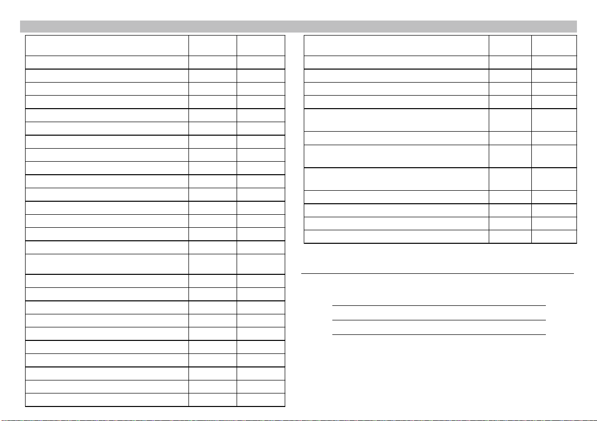
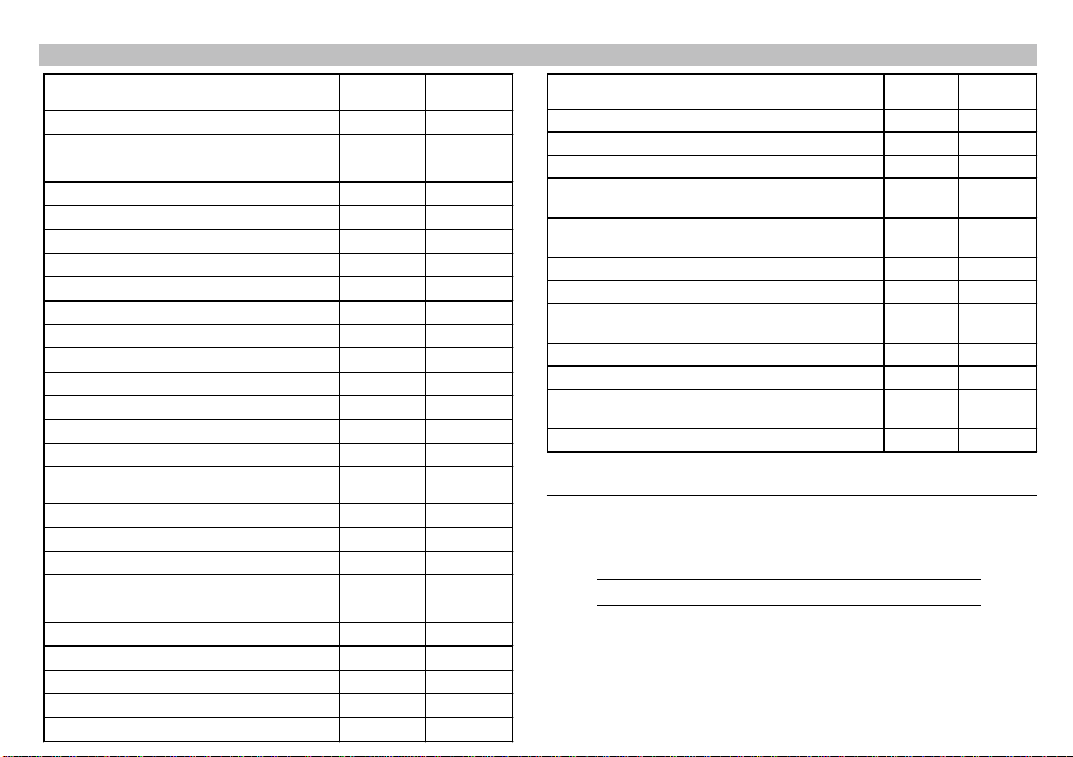
3. TABELLE DI PROGRAMMAZIONE
Ilpresente paragraforiporta le tabelle chel’installatore deveutilizzareper programmare
l’apparecchiatura di comando.
NOTA - I modi di funzionamento, le funzioni e le impostazioni elencanti nelle tabelle di
programmazione sono descritti dettagliatamente nelle istruzioni
dell’apparecchiaturaelettronica professionale.
TABELLA DELLE FUNZIONI
Le funzioni da 00 a 06 sono molto utili in fase di installazione per verificare la corretta
messa in funzione dell’automazione.Simulano l’attivazione dei seguenti ingressi:
Apre/Start 00
Start anta singola 01
Stop 02
Chiude 03
Start apertura parziale 04
Sicurezza standard (fotocellula 1) 05
Sicurezza supplementare (fotocellula 2) 06
Disponibile per sviluppi futuri 07
Disponibile per sviluppi futuri 08
Disponibile per sviluppi futuri 09
Esempio:
1) tramite i tasti “freccia” selezionare la funzione 01 - Start anta singola - verificandone
il numero identificativo sui 2 digit di sinistra ➀.
2) premere il tasto ENTER.
3) il cancello battente compirà un’apertura con l’anta singola.

Regolazioni Codice
funz. Valore
parametro
Ritardo anta in apertura (solo battenti) 10 0-20
Ritardo anta in chiusura (solo battenti) 11 0-20
Velocità avvicinamento / Rallentamento 12 0-15(*)
Tempo di pausa 13 1-90(*)
Tempo di lavoro 14 1-90(*)
Ritardo attivazione freno (solo scorrevoli) 15 0-20
Regolazione antischiacciamento 16 0-99
Ampiezza apertura parziale (solo scorrevoli) 17 0-32
Disponibile per sviluppi futuri
18 0-99
Disponibile per sviluppi futuri
19 /
Disponibile per sviluppi futuri
20 /
Disponibile per sviluppi futuri
21 /
Disponibile per sviluppi futuri
22 /
Disponibile per sviluppi futuri
23 /
Disponibile per sviluppi futuri
24 /
Modi di funzionamento Codice
funz. Valore
parametro
Automatico 25 0
Automatico speciale 25 1
Automatico super 25 2
Diagnostica 25 3
Semiautomatico apre/chiude 25 4
Semiautomatico con stop 25 5
Semiautomatico con inversione 25 6
Uomo presente 25 7
Semaforo 25 8
Disponibile per sviluppi futuri
25 9
Modi di funzionamento Codice
funz. Valore
parametro
Prelampeggio apertura: ON (1) o OFF (0) 35 0/1
Prelampeggio chiusura: ON (1) o OFF (0) 36 0/1
Colpo di sgancio (battenti): ON (1) o OFF (0) 37 0/1
Inversione a fine ciclo (basculanti): ON (1) o OFF (0) 38 0/1
START automatico (0) o START manuale (1) con
sicurezza supplementare non attivata 39 0/1
Base di rallentamento: 8 (0) o 19 (1) semionde 40 0/1
Gestione antischiacciamento: limitazione (0) o
STOP (1) 41 0/1
Sicurezza supplementare attivata: STOP (0) o
STOP + breve inversione (1) 42 0/1
Fotocellule: standard (0) o con azzeramento (1) 43 0/1
Abilitazione antischiacciamento: ON (1) o OFF (0) 44 0/1
No start con sic. standard attivata: ON (1) o OFF (0) 45 0/1
Disponibile per sviluppi futuri
46-50 /
(*) I valori dei parametri 12, 13 e 14 per l’apparecchiatura T4-P sono rispettivamente
0-99, 1-80 e 1-90.
TABELLA GENERALE DI PROGRAMMAZIONE
Le funzioni 98 e 99 permettono di trasferire tutte le impostazioni e regolazioni dal
programmatore alla scheda di controllo e viceversa.
Trasferimento dati, da una automazione al programmatore 98
Trasferimento dati, dal programmatore all’automazione 99
Queste ultime due funzioni sono particolarmente utili quando si dispone di due o più
impianti uguali.E’infatti possibile programmare un solo impianto e quindi trasferire tutti
i dati agli altri impianti con una sola operazione.
Per l’esecuzionedi questa funzioneè necessario mantenere premutoil tastoENTER
per almeno 5 secondi.

3
ENGLISH
Aprimatic S.p.A.• Zona Industriale Fossatone
40060 Villa Fontana • Medicina • Bologna (ITALY)
tel.+39-051.6979511 • fax +39-051.6930396
Safety recommendations
• The manufacturer’s instructions must be strictly observed.
• The installer must check that the device is operating correctly.
• Do NOT use the product incorrectly or for purposes not envisaged.
• Do NOT tamper with or modify the product.
• Refer to the manual for the device to be programmed for the safety standards to be
adopted during installation.
Purpose of the manual
This manual has been drawn up by the manufacturer and is an integral part of the
product.
The information contained in this manual is for expert operators who install the product
and carry out extraordinary maintenance.They must have specific skills to carry out the
operations correctly and in complete safety. Constant observance of the information in
this manual guarantees the safety of persons, low running costs and a longer life for the
product.Topreventincorrectuseandtheconsequentriskofaccidents,readthismanually
thoroughly and carefully and follow the instructions in full.
Application range
Programmer for Aprimatic electronic devices.
Contents
1. Description.................................................................................................. 4
1.1 Keys and display ................................................................................... 4
2. User instructions ......................................................................................... 4
2.1 Card connection procedure ................................................................... 4
2.2 Parameter/function setting procedure.................................................... 4
3. Programming tables .................................................................................... 4
Functions table ........................................................................................... 4
General programming table ......................................................................... 5

1. DESCRIPTION
TheProgrammeris anelectronicdevice used forprogrammingcontrol equipment, which
may be connected with a quick-fit connector present on the printed circuit card.
This device allows the installer to carry out all the adjustments and settings required
during installation or setting-up,withouthavingto adjustthe trimmersand DIP-switches.
Once programming is completed, the programmer must be disconnected from the card.
1.1 KEYS AND DISPLAY
The programmer consists of 5 keys and 1 four-digit display, as shown in the diagram:
a) 2“ARROW”keys used to select the function or the parameter to be modified (←back
→forward)
b) 2 increment and decrement keys for setting the value required (+ and -)
c) a central ENTER key for confirming the setting, which saves the value in a memory
(EEPROM) present on the control card.The value remains saved even if there is a
power failure.
The 4-digit display shows the following values:
• 2 right-side digits: value of the parameter ➁
• 2 left-side digits: identification number for the parameter/function to be modified ➀
Example: if the display indicates 13 50, it means that the “Pause time” parameter has
been selected (identification number 13) and this parameter is currently set at 50% (50)
of the maximum value permitted for this type of operator.
PROGR.EPS
2 Left-side digits:
function or
parameter selected
2 right-sided digits:
value of the
parameter selected
or the setting
Increment key
Confirms the data
set or selected
“FORWARD”
arrow key
“BACK”arrow key
Decrement key
Display

ENGLISH 4
2. USER INSTRUCTIONS
Caution - The product may only be used by the skilled technical personnel of the
assistance and/or assembly service.
Caution - The programmer connector can only be inserted in one direction. If you
have to force it in, check that the direction is correct.
2.1 CARD CONNECTION PROCEDURE
Caution - Before connecting the programmer, make sure that the control card is not
powered up.
1. Connect the programmer to the control card, inserting the mobile connector into the
fixed connector on the control card.To identify the position of the fixed connector on
the control card, refer to the instructions for the device.
2. Power up the system.
3. The programmer is supplied with power by means of the connection with the control
card. If there are no problems, the display must be lit.
2.2 PARAMETER/FUNCTION SETTING PROCEDURE
NOTE - If the programmer is not used for 10 seconds while connected to the control
card, the display goes OFF.Press any key to turn it ON again.
1. Use the ARROW keys to select the function or the parameter you want to set or
modify, checking the identification number on the two left-side digits ➀(see table
below).
2. When you have selected the parameter or function required, use the+and – keys to
change the value and read the value on the two right-side digits ➁(see table below).
3. Press ENTER to confirm the value set.
4. Inthe event of an error or if youneed to change the valueagain,repeat the procedure
from point 1.
5. When you have finished all the settings or adjustments, disconnect the power supply
and disconnect the programmer from the control card.Do NOT pull the cable.
NOTE - Currently, there are several“free” functions/parameters (from 51 to 97).During
the search stage, they are skipped by the programmer.
3. PROGRAMMING TABLES
Thissectionincludes the tables which the installer must use for programmingthe control
equipment.
NOTE - The operating modes, functions and settings listed in the programming tables
are described in detail in the instructions for the professional electronic
equipment.
FUNCTIONS TABLE
The functions from 00 to 06 are very useful during installation to check the correct
setting of the operator.They simulate the enabling of the following inputs:
Open/Start 00
Single wing start 01
Stop 02
Close 03
Partial opening start 04
Standard safety function (photocell 1) 05
Additional safety function (photocell 2) 06
Available for future functions 07
Available for future functions 08
Available for future functions 09
Example:
1)use the“arrow”keystoselectfunction01 - Singlewingstart- and checktheidentification
number on the two left-side digits ➀.
2) press ENTER.
3) one wing of the swing gate will open.

Functions 98 and 99 are used to transfer all the settings and the adjustments from the
programmer to the control card and vice versa.
Data transfer from an operator to the programmer 98
Data transfer from the programmer to the operator 99
These two functions are very useful when there are two or more identical systems.It is
possible to program only one system and then transfer all the data to the other systems
with a simple operation.
To apply this function, hold down ENTER for at least 5 seconds.
GENERAL PROGRAMMING TABLE
Adjustments Function
code Parameter
value
Wing opening delay (swing gates only) 10 0-20
Wing closing delay (swing gates only) 11 0-20
Approach/Slow-down speed 12 0-15(*)
Pause time 13 1-90(*)
Work time 14 1-90(*)
Brake enabling delay (sliding gates only) 15 0-20
Anti-crush device adjustment 16 0-99
Partial opening span (sliding gates only) 17 0-32
Available for future functions
18 0-99
Available for future functions
19 /
Available for future functions
20 /
Available for future functions
21 /
Available for future functions
22 /
Available for future functions
23 /
Available for future functions
24 /
Operating modes Function
code Parameter
value
Automatic 25 0
Special automatic 25 1
Super automatic 25 2
Diagnostics 25 3
Open/Close semiautomatic 25 4
Semiautomatic with stop 25 5
Semiautomatic with reverse 25 6
Dead man 25 7
Traffic lights 25 8
Available for future functions
25 9
(*) The values of parameters 12, 13 and 14 for the T4-P are, respectively, 0-99, 1-80
and1-90.
Operating modes Function
code Parameter
value
Opening pre-flashing: ON (1) or OFF (0) 35 0/1
Closing pre-flashing: ON (1) or OFF (0) 36 0/1
Release stroke (swing gates): ON (1) or OFF (0) 37 0/1
Reverse at end of cycle (up-and-over garage doors):
ON (1) or OFF (0) 38 0/1
Automatic START (0) or manual START (1) with
additional safety device not triggered 39 0/1
Slow-down base: 8 (0) or 19 (1) semi-waves 40 0/1
Anti-crush management: thrust limiter (0) or STOP (1) 41 0/1
Additional safety photocell enabled: STOP (0) or STOP
+ brief reverse movement (1) 42 0/1
Photocells: standard (0) or with reset (1) 43 0/1
Anti-crush enabling: ON (1) or OFF (0) 44 0/1
No start with standard safety function triggered: ON (1)
or OFF (0) 45 0/1
Available for future functions
46-50 /

Aprimatic S.p.A.• Zona Industriale Fossatone
40060 Villa Fontana • Medicina • Bologna (ITALY)
tel.+39-051.6979511 • fax +39-051.6930396
5
FRANÇAIS
Normes de sécurité
• Effectuer les interventions de la façon spécifiée par le fabricant.
• L’installateur doit vérifier si le dispositif fonctionne correctement.
• Ne pas utiliser le produit dans des buts différents de ceux qui ont été établis.
• Ne pas fausser ou modifier le produit.
• Faites référence au manuel du dispositif à programmer pour les normes de sécurité
à adopter en phase d’installation.
But du manuel
Ce manuel a été rédigé par le fabricant et fait partie intégrante du produit.
Les informations qui y sont contenues s’adressent aux opérateurs spécialisés qui
effectuent l’installation et les interventions d’entretien extraordinaire. Ceux-ci doivent
posséder des compétences spécifiques pour effectuer, correctement et dans des
conditionsde sécurité,les interventionsqui leurincombent.L’observationconstante des
instructions contenuesdanscemanuelgarantit la sécuritédes personnes,uneéconomie
de service et une plus longue durée de fonctionnement du produit. Pour éviter toutes
fausses manœuvres et donc tous risques d’accidents, lire attentivement ce manuel et
respecter scrupuleusement les informations qui y sont contenues.
Champ dapplication
Programmateur pour dispositifs électroniques Aprimatic.
Sommaire
1. Description.................................................................................................. 6
1.1 Touches et afficheur .............................................................................. 6
2. Mode d’emploi ............................................................................................ 6
2.1 Raccordement à la carte ....................................................................... 6
2.2 Sélection des paramètres/fonctions ...................................................... 6
3. Tables de programmation............................................................................ 6
Table des fonctions ..................................................................................... 6
Table générale de programmation ............................................................... 7

1. DESCRIPTION
Le programmateur est un système électronique de programmation à brancher par le
biais d’un connecteur à raccord rapide présent sur la carte électronique à programmer.
Ce système permet à l’installateur d’effectuer tous les réglages et les sélections
nécessaires en phase d’installation ou de mise au point, sans devoir régler aucun
potentiomètre, ni interrupteur DIP.
Une fois la programmation terminée, le programmateur doit être débranché de la carte.
1.1 TOUCHES ET AFFICHEUR
Leprogrammateurest forméde 5 touches et 1 afficheur à quatrechiffres,comme illustré
dans le dessin :
a) 2 “FLECHES”de direction qui permettent de sélectionner la fonction ou le paramètre
à modifier (←flèche en arrière et →flèche en avant)
b) 2 touches d’incrémentation et de décrémentation qui permettent de sélectionner la
valeur souhaitée (+ et -)
c) une touche (ENTER) au centre, pour valider la sélection, en mémorisant la valeur
dansune mémoire (EEPROM)delacartedecontrôle.La valeurrestedonc mémorisée
même en cas de coupure de courant.
L’afficheur à 4 chiffres visualise les valeurs suivantes :
• les 2 chiffres de droite : valeur du paramètre ➁
• les 2 chiffres de gauche : code du paramètre ou fonction à modifier ➀
Exemple : si l’afficheur visualise les chiffres 13 50, cela veut dire que vous avez
sélectionné le paramètre “Temps de pause” (code 13) et que ce paramètre a comme
valeur courante 50, soit 50% de sa valeur maximale admissible pour ce type
d’automatisme.
PROGR.EPS
les 2 chiffres de
gauche : fonction ou
paramètre
sélectionné
les 2 chiffres de
droite : valeur du
paramètre
sélectionné ou de
la fonction
Touche
d’incrémentation
Valide la donnée
paramétrée ou
sélectionnée
Flèche de direction
“AVANT”
Flèche de direction
“ARRIERE”
Touchede
décrémentation
Afficheur

FRANÇAIS 6
2. MODE DEMPLOI
Attention - Le produit ne peut être utilisé que par des installateurs agréés et/ou des
techniciens qualifiés du service d’assistance Aprimatic.
Attention - Le connecteur du programmateur ne peut être inséré que dans un seul
sens.Si la connexion vous paraît forcée, contrôlez si le connecteur a été
inséré dans le bon sens.
2.1 RACCORDEMENT A LA CARTE
Attention - Avantde procéder au raccordementdu programmateur,vérifiez si lacarte
de contrôle est bien hors tension.
1. Reliez le programmateur à la carte de contrôle en insérant le connecteur mobile sur
le connecteur fixe présent sur la carte de contrôle. Pour trouver la position du
connecteur fixe sur la carte de contrôle, référez-vous aux instructions du dispositif.
2. Mettez l’équipement sous tension.
3. Le programmateur est alimenté par le biais de sa connexion à la carte de contrôle.A
ce stade et si tout fonctionne correctement, l’afficheur doit s’éclairer.
2.2 SELECTION DES PARAMETRES/FONCTIONS
NOTA -Si le programmateur reste inactif pendant 10 secondes alors qu’il est relié à la
carte de contrôle, l’afficheur s’éteint. Pour le rallumer, il suffit de presser une
touchequelconque.
1. Avecles FLECHES de direction,sélectionnezleparamètreou la fonction souhaité(e),
en vérifiant le code sur les 2 chiffres de gauche ➀(voir table jointe).
2. Après avoir sélectionné le paramètre ou la fonction souhaité(e), modifiez la valeur
avec les touches +et –en lisant la valeur sur les 2 chiffres de droite ➁ (voir table
jointe).
3. Validez la valeur sélectionnée avec ENTER.
4. Pour corriger une erreur ou si vous devez modifier une donnée saisie, recommencez
la procédure en partant du point 1.
5. Après avoir terminé toutes les sélections, mettez l’installation hors tension et
débranchez le programmateur de la carte de contrôle, par le biais du connecteur,
sans tirer le câble.
NOTA - Ilexisteactuellement de nombreuxemplacementsdefonction/paramètre“libres”
(du 51 au 97). Pendant la phase de recherche, le programmateur saute les
emplacements vacants.
3. TABLES DE PROGRAMMATION
Cettesection contient les tablesque l’installateur doitutiliserpourprogrammer le dispositif
de commande.
NOTA - Les modes de fonctionnement, les fonctions et les sélections contenus dans
lestables de programmation sont décritsplusen détail dans lesinstructions du
dispositif électronique professionnel.
TABLE DES FONCTIONS
Les fonctions de 00 à 06 sont très utiles en phase d’installation pour vérifier le
fonctionnement de l’automatisme.Elles simulent l’activation des entrées suivantes :
Ouvrir/Fermer 00
Marche un seul vantail 01
Arrêt 02
Fermer 03
Marche ouverture partielle 04
Sécurité standard (cell.photoélectr.1) 05
Sécurité supplémentaire (cell.photoélectr.2) 06
Entrée libre 07
Entrée libre 08
Entrée libre 09
Exemple :
1) avec les“flèches” de direction, sélectionnez la fonction 01 - Marche un seul vantail -
vérifiant le numéro de code sur les 2 chiffres de gauche ➀.
2) pressez ENTER.
3) un seul vantail du portail s’ouvrira.

TABLE GENERALE DE PROGRAMMATION
Les fonctions 98 et 99 permettent de transmettre toutes les sélections et réglages du
programmateur à la carte de contrôle et vice versa.
Transmission de données, de l’automatisme au programmateur 98
Transmission de données, du programmateur à l’automatisme 99
Ces deux dernières fonctions sont particulièrement utiles si vous disposez de deux ou
plusieurs équipements identiques. Il est en effet possible de programmer un seul
équipement et de transmettre toutes les données aux autres par une seule opération.
Pour exécuter cette fonction, vous devez presser ENTER pendant au moins 5
secondes.
Réglages Code
fonct. Valeur du
paramètre
Retard du vantail en ouverture (ouvrants uniquement) 10 0-20
Retard du vantail en fermeture (ouvrants uniquement) 11 0-20
Vitesse d’approche / Ralentissement 12 0-15(*)
Temps de pause 13 1-90(*)
Temps de travail 14 1-90(*)
Retard activation du frein (coulissants uniquement) 15 0-20
Réglage anti-écrasement 16 0-99
Largeur d'ouverture partielle (coulissants uniquement) 17 0-32
Libre
18 0-99
Libre
19 /
Libre
20 /
Libre
21 /
Libre
22 /
Libre
23 /
Libre
24 /
Modes de fonctionnement Code
fonct. Valeur du
paramètre
Automatique 25 0
Automatique spécial 25 1
Automatique super 25 2
Diagnostic 25 3
Semi-automatique ouvrir/fermer 25 4
Semi-automatique avec arrêt 25 5
Semi-automatique avec inversion 25 6
Homme présent 25 7
Feux de signalisation 25 8
Libre
25 9
Modes de fonctionnement Code
fonct. Valeur du
paramètre
Préclignotement en ouverture : ON (1) ou OFF (0) 35 0/1
Préclignotement en fermeture : ON (1) ou OFF (0) 36 0/1
Coup de décrochage (ouvrants) : ON (1) ou OFF (0) 37 0/1
Inversion en fin de cycle (basculantes) : ON (1) ou OFF (0) 38 0/1
MARCHE automatique (0) ou MARCHE manuelle (1) avec
sécurité supplémentaire non activée 39 0/1
Base de ralentissement : 8 (0) ou 19 (1) demi-ondes 40 0/1
Gestion anti-écrasement : limitation (0) ou ARRET 41 0/1
Sécurité supplémentaire activée : ARRET (0) ou ARRET +
courte inversion (1) 42 0/1
Cellules photoélectriques : standard (0) ou avec mise à
zéro (1) 43 0/1
Activation anti-écrasement : ON (1) ou OFF (0) 44 0/1
Marche annulée avec séc. standard activée : ON (1) ou
OFF (0) 45 0/1
Libre
46-50 /
(*) Les valeursdesparamètres12, 13 et 14 pourledispositifT4-P sont respectivement
0-99, 1-80 et 1-90.

Aprimatic S.p.A.• Zona Industriale Fossatone
40060 Villa Fontana • Medicina • Bologna (ITALY)
Tel.+39-051.6979511 • Fax +39-051.6930396
7
DEUTSCH
Sicherheitsvorschriften
• Die Arbeiten müssen nach den Angaben des Herstellers durchgeführt werden
• Das Montagepersonal muß den einwandfreien Betrieb des Geräts überprüfen.
• DasProdukt darfausschließlichfürden vomHerstellervorgesehenenZweckverwendet
werden.
• Am Produkt dürfen keine Änderungen vorgenommen werden.
• Bezüglich der bei der Installation zu beachtenden Sicherheitsvorschriften sind die im
Handbuch des Programmiergeräts enthaltenen Hinweise zu beachten.
Zweck des Handbuchs
Dieses Handbuch wurde vom Hersteller verfaßt und ist wesentlicher Bestandteil des
Produkts.
Die darin enthaltenen Informationen richten sich an erfahrenes Montage- und
Wartungspersonal.DiesesPersonalmußüber spezifische Kenntnisseverfügen,umdie
Arbeit korrekt und unter sicheren Bedingungen durchführen zu können.Die Beachtung
derAnweisungengewährleistetSicherheit, wirtschaftlichenBetriebderAnlageund eine
lange Lebensdauer der Einrichtung.Zur Vermeidung von Fehlbedienung und folglicher
Unfallgefahr dieses Handbuch aufmerksam durchlesen und die Anweisungen genau
befolgen.
Anwendungsbereich
Programmiergerät für elektronische Aprimatic-Steuerungen.
Inhalt
1. Beschreibung .............................................................................................. 8
1.1Tasten und Display ................................................................................ 8
2. Bedienungsanleitung................................................................................... 8
2.1 Anschluß an die Karte........................................................................... 8
2.2 Einstellung der Parameter/Funktionen .................................................. 8
3. Programmiertabelle..................................................................................... 8
Tabelle der Funktionen ................................................................................ 8
AllgemeineProgrammiertabelle .................................................................. 9

1. BESCHREIBUNG
Bei dem Programmiergerät handelt es sich um ein elektronisches Gerät zur
Programmierung der Steuerung.Es kann mit der entsprechenden Steckverbindung an
die gedruckte Schaltung angeschlossen werden.
Mit Hilfe dieses Geräts kann der Monteur alle Einstellungen vornehmen, die bei der
Installation bzw.Einrichtung nötig sind, ohne daß dabei Trimmpotentiometer oder DIP-
Switches eingestellt werden müssen. Nach erfolgter Programmierung wird das Gerät
wieder von der Karte getrennt.
1.1 TASTEN UND DISPLAY
Das Programmiergerät ist mit 5Tasten und einem 4-stelligen Display ausgestattet, wie
in der Abbildung gezeigt:
a) 2 “PFEIL”-Tasten, mit denen die Funktion bzw. der Parameter ausgewählt wird, der
geändert werden soll (←Pfeil rückwärts und →Pfeil vorwärts)
b) 2 Aufwärts- und Abwärtstasten, mit denen der gewünschte Wert eingestellt werden
kann (+ und -)
c) eine zentraleTaste (ENTER) zum Bestätigen der Eingabe.Mit dieser Taste wird der
Wert in einem Speicher (EEPROM) auf der Steuerkarte abgelegt. Der Wert bleibt
also auch bei Stromausfall gespeichert.
Am 4-stelligen Display werden folgende Werte angezeigt:
• 2 Stellen rechts:Wert des Parameters ➁
• 2 Stellen links: Identifikationsnummer des Parameters/der Funktion, die geändert
werden soll ➀
Beispiel: Erscheinen am Display die Zahlen 13 50, bedeutet dies, daß der Parameter
“Pausenzeit” (mit der Identifikationsnummer 13) ausgewählt und auf 50% (50) des für
diesen Automationstyp maximal zulässigen Werts eingestellt ist.
PROGR.EPS
2 Stellen links:
gewählte Funktion
bzw.gewählter
Parameter
2 Stellen rechts:
Wert des
gewählten
Parameters oder
der Einstellung
Aufwärtstaste
Bestätigung des
eingegebenen oder
gewählten Werts
Pfeiltaste
“VORWÄRTS”
Pfeiltaste
“RÜCKWÄRTS”
Abwärtstaste
Display

DEUTSCH 8
2. BEDIENUNGSANLEITUNG
Achtung - Das Gerät darf ausschließlich von qualifizierten Technikern des Kunden-
bzw.Montagedienst verwendet werden.
Achtung - Der Steckverbinder des Programmiergeräts kann nur in einer Stellung
gesteckt werden. Sollte sich der Steckverbinder nicht problemlos stecken
lassen, muß die Steckposition überprüft werden.
2.1 ANSCHLUSS AN DIE KARTE
Achtung - Vor demAnschluß des Programmiergeräts, muß sichergestellt werden, daß
dieVersorgung der Steuerkarte unterbrochen ist.
1. DasProgrammiergerätmitHilfedesSteckverbindersan den Anschluß der Steuerkarte
anschließen. Bezüglich der Anordnung des Anschlusses auf der Steuerkarte siehe
die Betriebsanleitung des Steuergeräts.
2. Die Anlage mit Spannung versorgen.
3. Das Programmiergerät wird über die Steuerkarte versorgt. Nun muß das Display,
sofern keine Störungen vorliegen, leuchten.
2.2 EINSTELLUNG DER PARAMETER/FUNKTIONEN
HINWEIS - Wird das an die Steuerkarte angeschlossene Programmiergerät 10
Sekunden lang nicht betätigt, erlischt das Display. Zum Einschalten muß
lediglich eine beliebigeTaste betätigt werden.
1. MitdenPFEILTASTENdieFunktionbzw.denParameter,der eingestellt bzw.geändert
werden soll, auswählen. Die Identifikationsnummer an den beiden Stellen auf der
linken Seite ➀überprüfen (sieheTabelle im Anhang).
2. Nach Auswahl der gewünschten Funktion bzw. des gewünschten Parameters, den
Wert mit Hilfe der Tasten +und – ändern. Den Wert an den beiden Stellen auf der
rechten Seite ➁ablesen (sieheTabelle im Anhang).
3. Den eingestellten Wert mit der Taste ENTER bestätigen.
4. Im Fall eines Fehlers, oder im Fall einer weiteren Änderung, ist das Verfahren ab
Punkt 1 zu wiederholen.
5. Nach Beendigung aller Einstellungen und Eingaben, die Versorgung der Anlage
unterbrechen und das Programmiergerät von der Steuerkarte trennen. Hierzu den
Steckverbinder abziehen und nicht am Kabel ziehen.
HINWEIS - Zur Zeit sind zahlreiche Funktions-/Parameteradressen “frei“ (von 51 bis
97). Beim Suchen werden diese Adressen vom Programmiergerät
übersprungen.
3. PROGRAMMIERTABELLEN
DieserAbschnitt enthält dieTabellen,diederMonteurzur ProgrammierungderSteuerung
verwendenmuß.
HINWEIS - Die Betriebsarten, die Funktionen und Einstellungen, die in den
Programmiertabellen aufgelistetwerden,werdenin der Bedienungsanleitung
derprofessionellenElektroniksteuerung ausführlichbeschrieben.
TABELLE DER FUNKTIONEN
DieFunktionenvon00bis 06 sind in der Installationsphase sehr nützlich, um die korrekte
InbetriebnahmederAutomatikzu überprüfen.Es wird dieAktivierungfolgenderEingänge
simuliert:
Öffnen/Start 00
Start Einzeltorflügel 01
Stop 02
Schließen 03
StartTeilöffnung 04
Standardsicherheitseinrichtung (Lichtschranke1) 05
Zusätzliche Sicherheitseinrichtung (Lichtschranke 2) 06
Für zukünftige Anwendungen 07
Für zukünftige Anwendungen 08
Für zukünftige Anwendungen 09
Beispiel:
1) Mit den “Pfeiltasten” die Funktion 01 - Start Einzeltorflügel - prüfen und die
Identifikationsnummer an den 2 Stellen auf der linken Seite ➀prüfen.
2) DieTaste ENTER drücken.
3) Das Flügeltor öffnet einen einzelnenTorflügel.

ALLGEMEINE PROGRAMMIERTABELLE
Die Funktionen 98 und 99 erlauben die Übertragung aller Eingaben und Einstellungen
vom Programmiergerät auf die Steuerkarte und umgekehrt.
Datenübertragung, von einer Automatik zum Programmiergerät 98
Datenübertragung, vom Programmiergerät zu einer Automatik 99
Dieseletzten beidenFunktionensindbesonders nützlich,wennzwei odermehreregleiche
Anlagenvorhandensind.Es istmöglich, nur eine einzige Anlagezu programmierenund
inder Folgealle DatenineinemeinzigenVorgangaufalleanderen Anlagen zuübertragen.
Zur Ausführung dieser Funktion muß dieTaster ENTER mindestens 5 Sekunden
lang gedrückt werden.
Einstellungen Code der
Funktion Parameter-
wert
Torflügelverzögerung beim
Ö
ffnen (nur Flügeltore) 10 0-20
Torflügelverzögerung beim Schließen (nur Flügeltore) 11 0-20
Annäherungsgeschwindigkeit / Bremsung 12 0-15(*)
Pausenzeit 13 1-90(*)
Betriebszeit 14 1-90(*)
Bremsverzögerung (nur Schiebetore) 15 0-20
Einstellung des Einklemmschutzes 16 0-99
Weite der Teilöffnung (nur Schiebetore) 17 0-32
Für zukünftige Anwendungen
18 0-99
Für zukünftige Anwendungen
19 /
Für zukünftige Anwendungen
20 /
Für zukünftige Anwendungen
21 /
Für zukünftige Anwendungen
22 /
Für zukünftige Anwendungen
23 /
Für zukünftige Anwendungen
24 /
Betriebsarten Code der
Funktion Parameter-
wert
Automatik 25 0
Spezialautomatik 25 1
Superautomatik 25 2
Diagnose 25 3
Halbautomatik
Ö
ffnen/Schließen 25 4
Halbautomatik mit Stop 25 5
Halbautomatik mit Umkehr der Laufrichtung 25 6
Totmannschaltung 25 7
Ampelschaltung 25 8
Für zukünftige Anwendungen
25 9
Betriebsarten Code der
Funktion Parameter-
wert
Vorblinken beim Öffnen: ON (1) oder OFF (0) 35 0/1
Vorblinken beim Schließen: ON (1) oder OFF (0) 36 0/1
Entriegelungsschlag (Flügeltore): ON (1) oder OFF (0) 37 0/1
Umkehrung der Laufrichtung am Zyklusende (Kipptore):
ON (1) oder OFF (0) 38 0/1
Automatischer START (0) oder manueller START (1) bei
nicht ausgelöster zusätzlicher Sicherheitseinrichtung 39 0/1
Bremsart: 8 (0) oder 19 (1) Halbwellen 40 0/1
Einklemmschutz: Begrenzung (0) oder STOP (1) 41 0/1
Belegte zusätzliche Lichtschranke: STOP (0) oder
STOP + kurzer Umkehrschlag (1) 42 0/1
Lichtschranke: Standard (0) oder mit Nullstellung (1) 43 0/1
Freigabe des Einklemmschutzes: ON (1) oder OFF (0) 44 0/1
No Start bei ausgelöster Standardsicherheitseinrichtung:
ON (1) oder OFF (0) 45 0/1
Für zukünftige Anwendungen
46-50 /
(*) Die Werte der Paramter 12, 13 und 14 der SteuerungT4-P sind jeweils 0-99, 1-80
und 1-90.

ESPAÑOL
Aprimatic S.p.A.• Zona Industriale Fossatone
40060 Villa Fontana • Medicina • Bologna (ITALY)
tel.+39-051.6979511 • fax +39-051.6930396
9
Normas de seguridad
• En la ejecución de las operaciones, atenerse a las indicaciones del constructor.
• Elinstaladortienelaobligaciónde controlar el correcto funcionamiento del dispositivo.
• Está prohibido utilizar el producto para usos distintos a los previstos o impropios.
• Está prohibido manipular o modificar el producto.
• Consultar el manual del equipo a programar para las normas de seguridad que hay
que adoptar durante la instalación del equipo.
Finalidad del manual
Estemanual ha sido redactado por el constructor y formaparteintegrantedel producto.
La información que contiene está dirigida a los operadores expertos encargados de la
instalación y el mantenimiento extraordinario. Dichos operadores tendrán que poseer
competencias y capacidades específicas para llevar a cabo correctamente y en toda
seguridad las operaciones de su competencia.Elrespetoconstantedelas instrucciones
del manual garantiza la seguridad del personal, economía de ejercicio y una mayor
duración del producto. Para evitar maniobras indebidas con el consiguiente riesgo de
accidentes, es importante leer con atención este manual y respetar escrupulosamente
las informaciones que contiene.
Campo de aplicación
Programador para equipos electrónicos Aprimatic.
Índice
1. Descripción ............................................................................................... 10
1.1 Teclas y display ................................................................................... 10
2. Instrucciones de uso ................................................................................. 10
2.1 Procedimiento de conexión de la tarjeta.............................................. 10
2.2 Procedimiento de planteamiento de parámetros/funciones ................. 10
3. Tablas de programación ............................................................................ 10
Tabla de funciones .................................................................................... 10
Tabla general de programación ................................................................. 11

1. DESCRIPCIÓN
El Programador es un dispositivo electrónico que se utiliza para la programación del
equipo de mando que puede conectarse por medio del conector dedicado con
acoplamiento rápido presente en la tarjeta circuito impreso.
Graciasa este dispositivoelinstaladorpuedeefectuartodos los ajustes y planteamientos
necesarios en la fase de instalación o puesta a punto, sin necesidad de regular trimmer
ni DIP-switch.
Finalizada la programación, el dispositivo se tiene que desconectar de la tarjeta.
1.1 TECLASY DISPLAY
El programador está formado por 5 teclas y 1 display de cuatro dígitos, ilustrados en la
figura:
a) 2 teclas “FLECHA” que permiten seleccionar la función o el parámetro a modificar
(←flecha atrás y →flecha adelante)
b) 2 teclas de incremento y decremento que permiten plantear el valor deseado (+ y -)
c) una tecla central para confirmar (ENTER) el planteamiento, que memoriza el valor
en una memoria (EEPROM) presente en la tarjeta de control. El valor permanece
memorizado incluso ante un fallo de la tensión de la línea principal.
El display de 4 dígitos visualiza los valores siguientes:
• 2 dígitos a la derecha: valor del parámetro ➁
• 2 dígitosa la izquierda:número de identificacióndel parámetro/función amodificar ➀
Ejemplo: si el display visualiza los dígitos 13 50, significa que se ha seleccionado el
parámetro “Tiempo de pausa” (con número de identificación 13) y actualmente este
parámetro está planteado en el 50% (50) del valor máximo admitido para esa clase de
automatización.
PROGR.EPS
2 dígitos a la
izquierda: función o
parámetro
seleccionado
2 dígitos a la
derecha: valor del
parámetro
seleccionado o del
planteamiento
Teclade
incremento
Confirma el dato
planteado o
seleccionado
Teclaflecha
“ADELANTE”
Teclaflecha
“ATRÁS”
Teclade
decremento
Display
Table of contents
Languages:
Other Aprimatic Motherboard manuals