APT 850C User manual

1
Product TFT LCD Display
Model 850C (DPC-14)
Abbreviation 850C-BF
VENTURE SCOOTERS
850c Display
User Manual

2
1.Product Name
TFT LCD display
Model : APT TFT 850C
2.Manufacturer
Tianjin APT Science and Technology Co., Ltd.
Email : yzhao@aptdevelop.com apt@aptdevelop.com
3.Electrical Parameters
3.2inch IPS screen
24V/36V/48V battery supply
Rated operating current : 40mA
Max operating current : 100mA (36V battery, with USB equipment changed)
USB changing port : 5V 500mA
Off leakage current < 1uA
Max output current to controller : 100mA
Operating temperature : -20~70℃, Storage temperature : -30~80℃
4.Dimensions & Material
Product shell is ABS, transparent window is made with high strength Acrylic.
Dimensions : host/L92mm*W60mm*H14mm

3
5.Features
Suitable for low temperature Max -20℃.
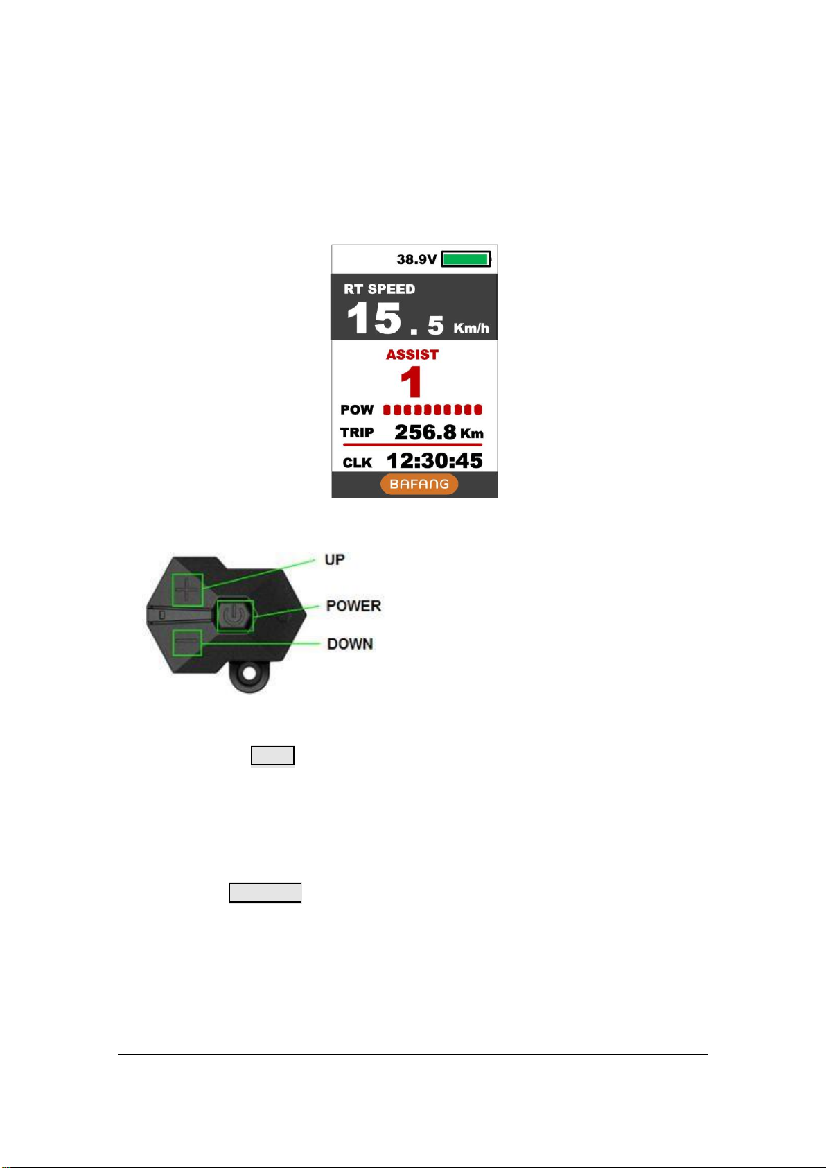
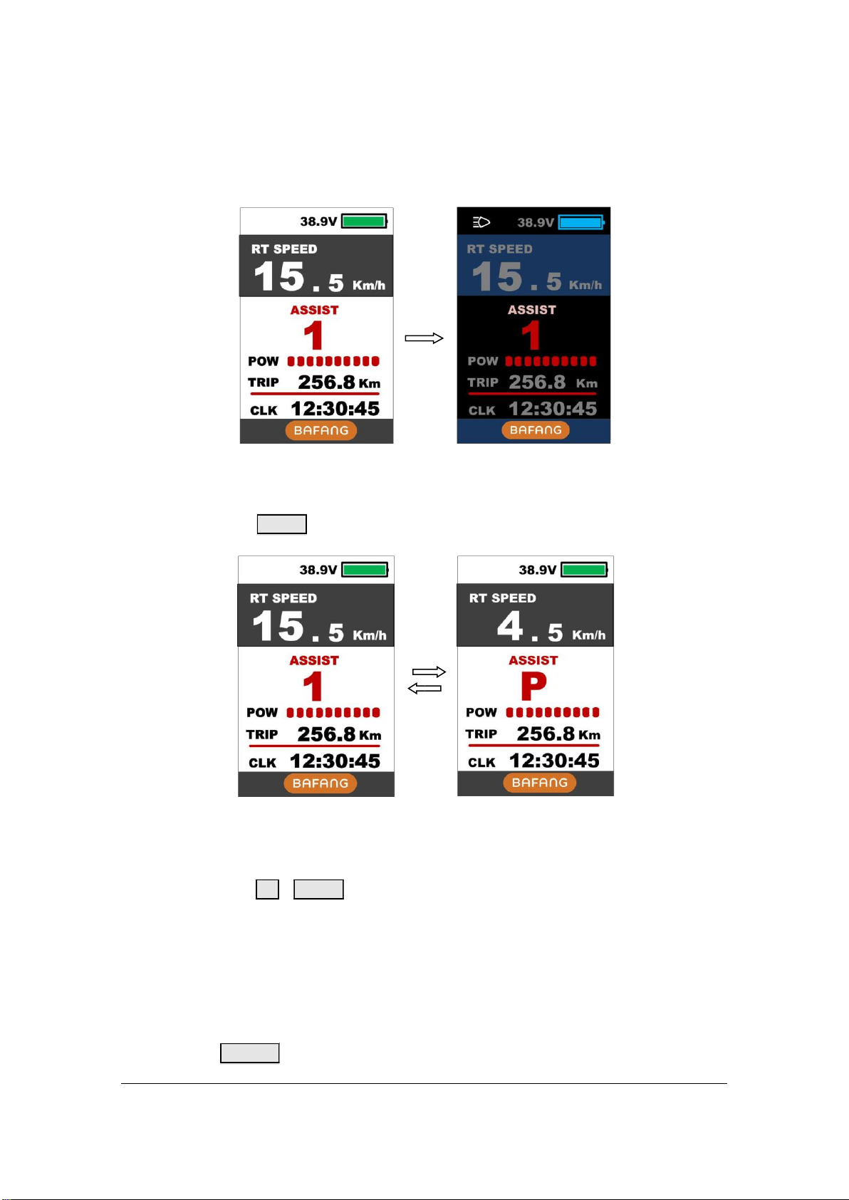
High-contrast 3.2inch IPS colourful matrix screen.
Ergonomic external button design, easy to operate.
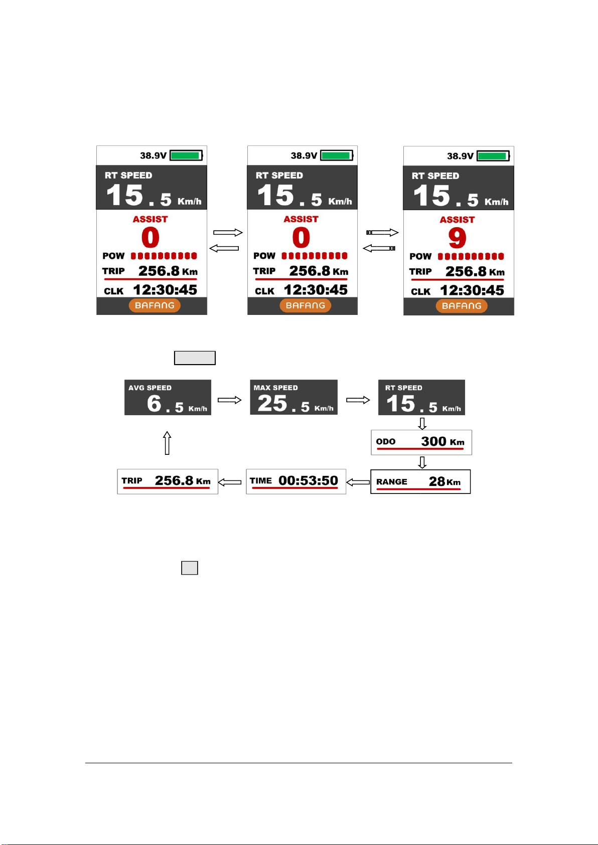
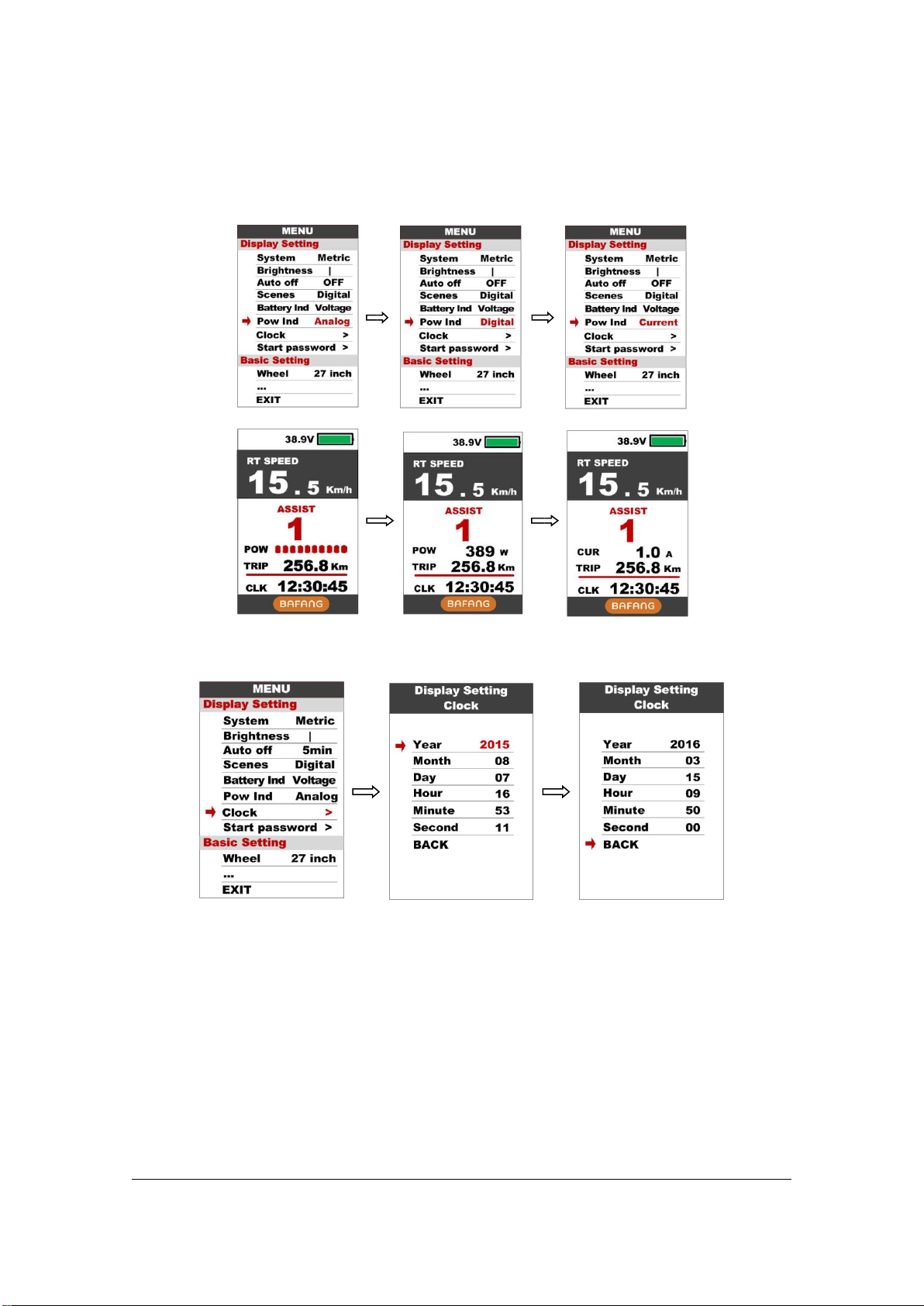
Speed display : AVG SPEED, MAX SPEED, SPEED (Real-time).
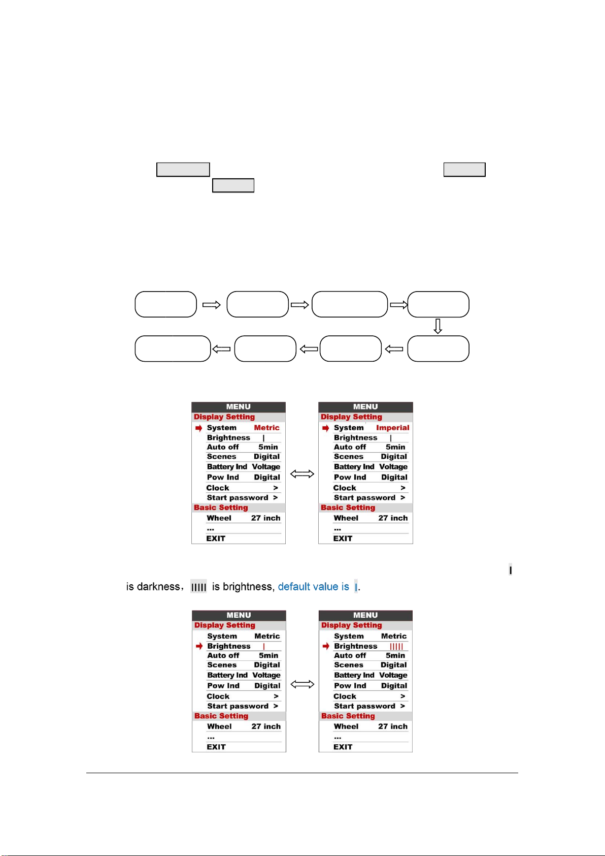
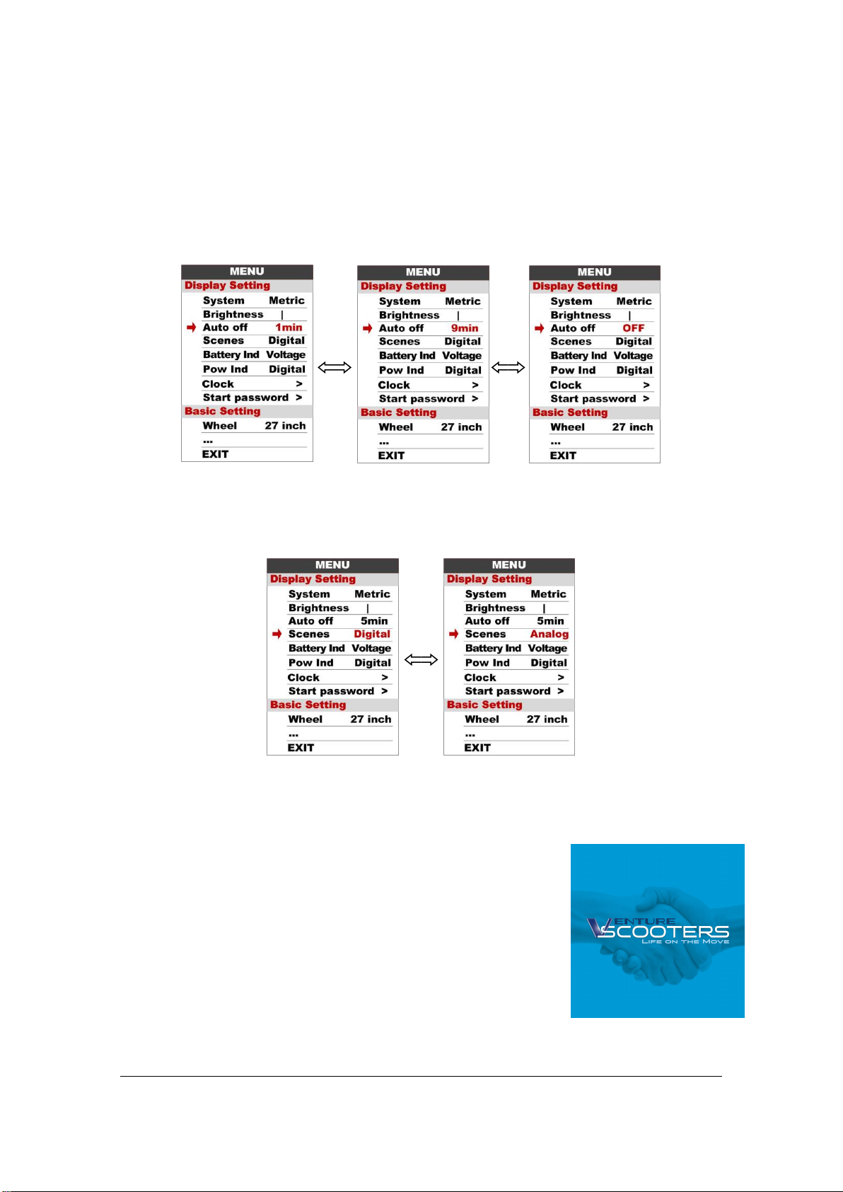
Kilometer / Mile : Can be set according to customers’ habits.
Smart battery indicator : Provide a reliable battery indicator.
9-level Assist : 3-level/5-level/9-level optional.
Mileage indicator : Odometer/Trip distance/ Clock/ Riding time.
Power/Current indicator : real time power indicator, digital or analog or Current.
Error code indicator: Displays error code if fault occurs.
Software upgraded : Software can be upgraded through UART.
USB charging port : 5V/500mAh

4
6.TFT screen instructions
7.Functional Description
7.1 Power On/Off
Press and hold button for 1 second can turn on/off the display. The Display can
shut down when there is no operate& ride for Xminutes(Xcould
automatically
be 0~9).
*If the display has been set password power on, you need to input the correct password before start.
7.2 Assist level operating
Short press button can change the assist level. Top assist level is 9, 0 for
neutral. Level quantities can be adjusted according to the customer
requirements.
Power
UP/DOWN

5
Short press button can change the speed and mileage mode, AVG SPEED-
>MAX SPEED->RT SPEED->ODO->RANGE->TIME->TRIP.
**If there is no operation for 5 seconds, display will return Speed (Real-Time) display automatically.
7.4 Headlight/backlight On/Off
Press and hold button for 1 second can turn on/off the headlight, and the scree will
switch to the corresponding mode.
*The motor does not work when the battery voltage is low, Display still can keep the headlight on for a
while when E-bike is in riding.
POWER
UP
7.3
Speed
&
Mileage
mode
switch

6
Daytime mode night mode
7.5 Walking mode (6km)
Press and hold button for 2 second can get into walking mode, out of the mode
when release the button.
7.6 Data cleanup
Press and hold buttons together for 1 second can reset several temporary
data, temporary data include AVG Speed / MAX Speed / Trip /
Time.
* These temporary data can’t be erased by power off.
8.Parameter setting
DOWN
UP
&
DOWN
POWER
*
This
feature
needs
to
be
supported
by
controller.

7
Double press button (press interval less than 0.3 second) can get into setting menus, press
button can switch
to next item. Double press button to exit from menu.
* Display will automatically quit menu when there is no operation for 30 seconds.
* For safety reasons, display can’t get into MENU when riding.
* Display will quit MENU when start riding.
The order of parameters are as follow.
8.1 System : Press Up / Down button to switch between Metric / Imperial.
8.2 Brightness : Press Up / Down button to change the brightness of the backlight,
UP/DOWN
buttons to change the parameter setting, press
POWER
POWER
Metric/Imperial
Brightness
Auto
off
Scenes
Battery
Ind
Pow
Ind
Start
password
Clock

8
8.3 Auto off : Press UP/DOWN button to change the auto power off time, from 1 to 9
or OFF, the number represent time (minutes) to shutdown, default value is 5
minutes.
8.4 Scenes : Press UP/DOWN button to change the scenes, Digital / Analog.
*Display only support Digital scenes for now, Analog scenes will be supported for future.
8.5 Battery Ind : Press UP/DOWN button to change the battery indicator, Voltage /
Percentage / OFF.
*Accurate percentage needs communication with battery.

9
8.6 Pow Ind : Press UP/DOWN button to change the Power indicator, Analog /
Digital/Current.
* This data represents power output of the battery (not motor).
Voltage
Percentage
OFF

10
8.7 Clock : Clock setting, press POWER button get into the clock setting menu, press
UP/DOWN button to set Year/Month/Day/Hour/Min/Sec.
8.8 Start password : Press POWER button get into the password setting menu. If you
had set Start input ON, you must input right password before power on, password is
accorded to your setting.

11
You need to input the right password before start with 30 seconds, display will power
off automatically if the password was wrong.
Basic Setting
show all items of the Basic Setting.
Wheel
Ad
v
ance
s
etting
Battery
Factory
setting
Information
*Press
DOWN
button
to
move
the
red
arrow
to
,
press
POWER
button
can

12
8.9 Wheel : Press UP/DOWN can change the wheel setting, optional wheel diameter is
16/18/20/22/24/26/27/27.5/28/29/30/31 inch, 51cm~255cm represent wheel
circumference (this needs controller support).
8.10 Battery : Press UP/DOWN will change battery voltage setting, optional value is
24V/36V/48V/UBE,UBE means user define value.
8.11 Advance setting : Press POWER button can get into the advance setting menu,
default password is ‘1919’.
8.12 Speed limit : Press UP/DOWN will change speed limit, range 10km/h~45km/h.
Default value is 25km/h.
Speed
limit
E
rror
code
Assist
levels

13
*Speed limit and current limit are restricted by controller and motor.
8.13 Assist levels : This parameter can customize assist levels, options are 3/5/9/UBE,
UBE represent factory default settings.
8.14 Error code :Display the last 10 times error code.
8.15Factorysetting :Press POWERbuttonenterRestoreFactorysettingsitem,set YES
will restore all parameter to factory settings.

14
8.16 Information : Show information of the E-bike.
8.17 Product info : Get into this item can show hardware version software version…
8.18 Battery info : Get into this item can show all information of battery, including
Voltage, Current, Avg Current, Cycle times, Capacity, Remaining Capacity , Full
Charge Capacity , Temperature, Max Tempt, Min Tempt , Relate ChgSta ,
Absolute ChgSta , Max Uncharge Times , Last Uncharge Times , CorVolt-1.
*These information needs to be supported by battery communication.
9.Error Code define
850C can show warning message, icon shows on the screen, and show error code at the
bottom of the screen, error code from 04~30, definition see the table below.
Error Code
Error description
Error diaplay

15
0x01
Normal
No error
0x03
Brake signal
No error
0x04
Throttle on high position
Display 04H on speed position
0x05
Throttle error
Display 05H on speed position
0x06
Low voltage protection
Display 06H on speed position
0x07
High voltage protection
Display 07H on speed position
0x08
Line of the Hall on motor
error
Display 08H on speed position
0x09
Phase line of the motor error
Display 09H on speed position
0x10
High temperature of
controller
Display 10H on speed position
0x11
Controller’s temperature
sensor error
Display 11H on speed position
0x12
Current sensor error
Display 12H on speed position
0x13
Battery’s temperature sensor
Display 13H on speed position
error
0x14
Motor‘s temperature
sensor error
Display 14H on speed position
0x21
Motor‘s speed sensor error
Display 21H on speed position
0x22
BMS communication error
Display 22H on speed position
0x23
Head light error
Display 23H on speed position
0x24
Head light sensor error
Display 24H on speed position
0x30
Communication error
Display 30H on speed position

16
10.Assembly instructions
Please pay attention to the screw’s torque value, damaged caused by excessive torque
is not within the scope of the warranty.
There are 2 directions for the clamp installation, forward or backward.

17
Clamps suit for 3 size of handlebar, 31.8mm, 25.4mm, 22.2mm, there are transfer rings for
25.4mm and 22.2mm, transfer ring must be assembled with the special directions, pay
attention to the green arrow below.
11.Connector descriptions
1、Red wire : Anode(24v/36v/48V)
2、Blue wire : Power cord to the controller
3、Black wire : GND
4、Green wire : RxD (controller -> display)
5、Yellow wire : TxD (display -> controller)
12.Assist level instructions
Assist level can be customized, the highest level is 9, common used assist level see the
table below:
3 level
5 level
9 level
0
0
No power assist
1
1
2
1
2
3
4
3
5

18
2
6
4
7
8
3
5
9
13.Certification
CE / IP65 (water proof) / ROHS.
Other manuals for 850C
1
Table of contents
Other APT Monitor manuals