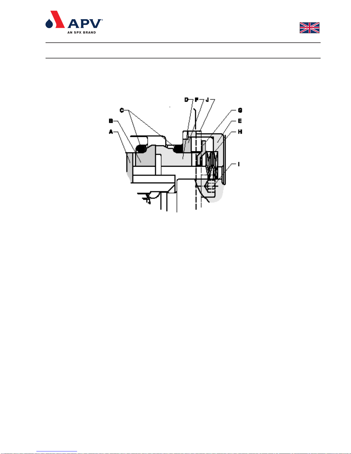
APV DW1 User manual

Instruction Manual
DW Pumps
Read and understand this manual prior to
operating or servicing this product.


453194 ISS 09.2006
Contents:
Section Page Description
- 2 Sectional Drawing - Pump
- 5 Sectional Drawing - Shaft seal
0. 7 Warnings
1. 8 Introduction to the DW range
1.1 - The DW range
1.2 - The DW Pump, options and extras
1.3 - Indentifying the pump model
1.4 - Indentification of motor
2. 9 Installation of the pump
2.1 - Handling and storage
2.2 - Positioning of the pump
2.3 - The pipe system
2.4 - Pump rotation
2.5 - Power supply
2.6 10 Water supply for water flushed seals
3. 10 Before start-up and starting the pump
3.1 - Checking the pump for foreign bodies
3.2 - Check the following before finishing the installation
3.3 11 Immediately after starting the pump
3.4 12 Fault finding
4. 13 Dismantling and re-assembling the pump
4.1 - Remove front cover
4.1.1 - Re-fit the front cover
4.2 - Remove the rotors
4.2.1 14 Re-fit the rotors
4.3 - Remove the rotor case
4.3.1 - Re-fit the rotor case
4.4 15 Remove can
4.4.1 - Re-fit can
4.5 - Remove lipseal holder
4.5.1 - Re-fit lipseal holder
4.6 - Remove the timing gears
4.6.1 16 Re-fit the timing gears
4.7 - Remove the oil seal plate
4.7.1 - Re-fit the oil seal plate
4.8 17 Remove the foot
4.8.1 - Re-fit the foot
4.9 - Adjustment of the rotors axial position
4.9.1 18 Adjustment of the rotors angular position
5. 19 Maintenance
5.1 - Replacing rotors
5.2 20 Replacement of single mechanical shaft seals
5.3 - Changing port orientation
5.4 21 Changing the bearings
5.5 22 Recommended holding of spare parts
6. 23 Technical data
6.1 - Tightening Torque Settings
6.2 24 Maximum differential and discharge pressures
6.3 - Maximum permissable moment
6.4 - Maximum permissable temperature
6.5 - Sound pressure and sound power level
6.6 26 Temperature changes and max. temperature
6.7 - Maximum permissable rotational speed
6.8 27 Clearance for adjustment
Section Page Description
7. - Spare parts list
- 36 Pump complete
- 64 Shaft seal, single mechanical
- 66 Baseplate
- 67 Motorshroud complete
- 68 Motorshroud spare part
- 70 Coupling guard
- 72 Pump dimensions
- 74 Pump dimensions with fittings
- 75 Fitting tools for pump flushing
- 76 Locking tool
- 77 Removal tool
Separate Manuals
7.1 - Dimensional sketches
- - Pump dimensions
- - Pump dimensions with fittings
- - Dimensional sketches for complete arrangement
8 - Accessories
8.1 - Shaft seal
8.2 - Thermal jacket
8.3 - Relief Valve
8.4 - Rectangular inlet
8.5 - Electro polishing
UK

2
453195 ISS U 09.2006
Sectional Drawing, pump complete

3
453195 ISS U 09.2006
Sectional Drawing, pump complete
Pos
1
2
3
4
5
6
7
9
10
11
13
17
18
20
21
22
23
24
25
26
27
28
29
30
31
32
Description
Front cover
Bolt, front cover
Bolt, front cover stepped
Nut, front cover dome
Gasket, front cover
Screw, rotor case to chassis
Dowel
Rotor case
Oil seal plate
O-ring, oil seal plate
Chassis
O-ring, can
Clamp ring
Seal consol
O-ring, seal consol
Oil seal rear
Oil filler plug
Screw, seal consol
Oil level window
Can
Oil drain plug
Nut
Foot, left
Foot, right
Screw for foot
Rotor screw with washer
Pos
34
35
36
37
38
39
40
42
43
44
45
45a
45b
47
48
48a
48b
49
50
51
52
53
54
55
56
Description
O-ring, rotor screw
Rotor
O-ring, rotor/shaft
Shims, rotor
Shaft main
Shaft aux
Gear key
Oil seal front
Drive key
Front spacer
Bearing front
Bearing front,inner bearing race
Bearing front, outer bearing race
Spacer, rear bearing
Bearing rear
Bearing rear, inner bearing race
Bearing rear, outer bearing race
Bearing rear tab washer
Bearing rear nut
Circlip
Gear spacer
Gear shims
Gear (1pair)
Gear tab washer
Gear nut

5
342229 ISS Z 04.2000
Sectional drawing - Shaft seal
Single mechanical seal
A: Rotary drive ring
B: Rotary seal face
C: O-ring, seal
D: Stationary seal face
E: Seal housing
F: Clamp plate
G: Stationary drive ring
H: Wave spring
I: Screw, seal housing
J: Clamp

7
453272 ISS U 09.2004
1. Read the instructions before installing and starting the pump. Always follow
the guidelines for assembly in order to secure optimum operational reliability.
If in doubt, contact your local APV dealer.
Electrical Installation
2. Always check that the specifications of the motor and the motor control unit
are correct, particularly in operating environments where there may be a risk
of explosion.
3. Always ensure that all electrical installation is carried out by qualified staff.
4. Never hose down the electric motor directly with water or cleaning fluids.
5. Never dismantle the pump before the power supply to the motor has been
disconnected. The fuses should be removed and the cable disconnected
from the motor.
6. Pumps should only be installed, disassembled, repaired and assembled by
personnel trained in servicing of APV pumps, or by APV fitters.
For further information, please contact your local APV dealer.
Personal Injury
7. Never start the pump before the coupling guard between pump and motor
has been securely fitted.
8. There are rotating parts in the pump. Never put hands or fingers into a pump
while it is in operation..
9. Never touch the gearbox of the pump as it can become very hot.
10. Never touch the rotor case during operation. If the pump is being used for
hot fluids the rotor case may become very hot.
11. Always ensure that all pipe connections have been fitted and tightened
properly before the pump is started. If the pump is used for hot and/or
hazardous liquids, special care must be taken. In such cases, follow the local
regulations for personal safety when working with these products.
12. Never dismantle the pump until the isolating valves on the suction and
discharge side have been closed and the immediate pipe system has been
drained. If the pump is used for hot and/or hazardous fluids, special
precautions must be taken. In such cases follow the local regulations for
personal safety when working with these products.
Pump damage
13. Always remove assembly tools from the pump before starting it up.
14. Always ensure that no debris of any kind is present in the pump.
15. Always ensure that the pump is filled with liquid before it is started.
16. Always ensure that the pump and the motor shafts are properly aligned .
17. Always ensure that the suction and discharge valves isolating the pump are
fully open before starting the pump.
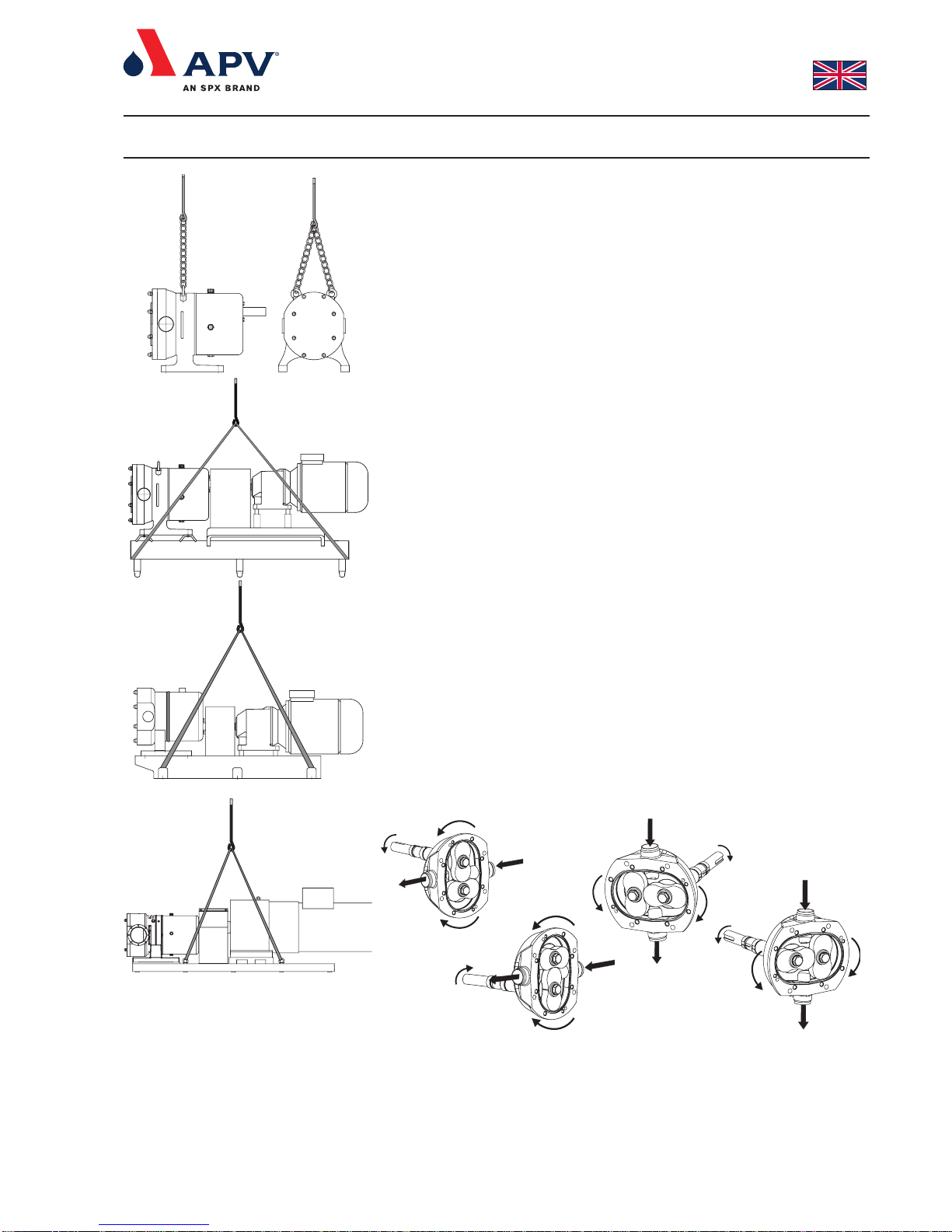
18. Always use securely fitted lifting straps when lifting the pump with a hoist or
similar lifting gear. Check whether there are any special lifting instructions.
19. Always ensure that the gearbox case is filled with an APV recommended
gear oil to the appropriate level.
20. Never close or obstruct the outlet of the pump as the pressure in the system
will increase above the specified maximum pressure of the pump and cause
damage to the pump.
21. Never drop parts - especially rotors and front covers - on the floor.
22. Never exceed the maximum temperature specified on the pump nameplate.
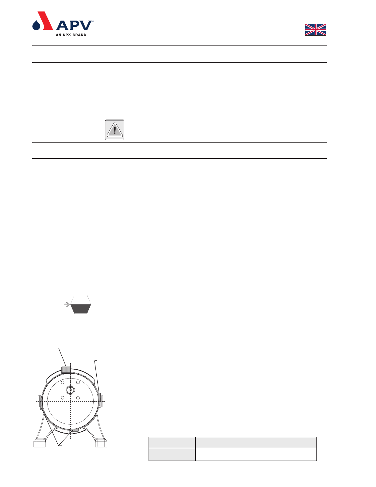
23. Never exceed the maximum allowable pressure specified below:
Max. 33 bar: DW6 and DW7
Max. 28 bar: DW5
Max. 23 bar: DW2; DW3 and DW4
Max. 18 bar: DW1
These pressures apply for water at 20°C.
The differential pressure must not exceed the pressure stated on the nameplate.
0. Warnings

8
453196 ISS E 04.2008
1.1 The DW range
This manual covers all sizes of standard DW and DWE pumps as
well as high temperature pumps. Check the nameplate of the pump
to ensure that you have one of the above versions.
1.2 The DW Pump, options and extras
The following standard options are available in the DW range:
- Bareshaft pump
- Pump with constant speed geared motor, suitable for inverter
drive use. Up to 37 kW these are available with stainless steel
motor shroud.
- Pump with geared motor with constant or manually variable
speed.
- Pump base plate and coupling guard in stainless steel.
- Lobe rotors suitable for max. 110°C or max.180°C product
temperature, in stainless steel 316L or Non Galling Alloy (NGA).
- Piston rotors suitable for max. 110°C product temperature, in
stainless steel 316L or NGA.
- Elastomers in EPDM, FPM (Viton) or ISOLASTTM.
- Single mechanical shaft seal in SiC/Carbon or SiC/SiC, flushed
or non-flushed.
- Double mechanical shaft seal in SiC/Carbon or SiC/SiC .
- Single EPDM lip seal for DW1-5.
- Triple PTFE lip seal (confectionary) for DW1-5.
- Packed gland with sealing thread in PTFE impregnation, for DW1-5.
- Horizontal or vertical suction and discharge ports.
- Rectangular inlet.
- Cooling/heating jacket on rotor case and front cover.
- Pressure relief valves on DW1-5.
1.3 Identifying the pump model
Example - See fig. 1.
ORDER NO: The APV order number of the pump
TYPE: Indicates the type of pump; in this case DW3/017/20
017: displacement volume in l/100 rpm
20: max. allowable differential pressure in bars
SERIAL NO: Indicates the serial number of the pump
YEAR: Indicates year of manufacture
TEMP 110: Max. product temperature in °C.
MAX. BAR 20: Max. differential pressure in bars
1.4 Indentification of motor
The motor is identified by means of the nameplate of the motor.
1. Introduction to the DW range
Fig. 1

9
453196 ISS E 04.2008
2 Installation of the pump
2.1 Handling and storage
Refer to the pump weight in the Spare Parts List page 73 before
selecting and using any lifting gear. Ensure that lifting equipment is
correctly rated and used within the specified limits.
The drawings on the left shows how the pump should be lifted.
DW1 - DW2 bareshaft pump: To be lifted manually with the hands.
Alternally eyebolts can be fitted and the pump lifted as DW3 - DW7.
(see fig. A)
DW3 - DW7 bareshaft pump: To be lifted with chain as shown in fig.
A.
DW1 - DW5 pump on baseplate type 1: To be lifted by putting straps
below the baseplate as shown in fig. B.
Fig. C: DW1 - DW6 pump on baseplate type 2: To be lifted by putting
straps below the baseplate as shown in fig. C.
Fig. D: DW6 - DW7 pump on baseplate type 3: To be lifted by putting
straps below the baseplate as shown in fig. D.
After receipt and inspection, if the pump is not to be installed immedia-
tely, the pump must be repacked and placed in suitable roofed storage.
The storage location must be clean, dry and free from vibration.
Plastic or gasket type port covers must be left in place.
If a moist or dusty atmosphere is used for storage, further protect the
pump and unit with a suitable cover.
2.2 Positioning of the pump
Install the pump as close to the liquid source as possible.
Keep the number of bends, tees, valves and other components in the
pipe system leading to the inlet of the pump to an absolute minimum.
Install the pump as low in relation to the liquid source as possible.
Install the pump with sufficient space for maintenance access.
2.3 The pipe system
Ensure that pipe unions are properly aligned and assembled.
Use appropriate gaskets.
Support the suction and discharge piping as close to the pump as
possible.
2.4 Pump rotation
Depending on the required flow direction and the position of the
shaft, the rotation direction of the pump is shown on fig. E, F, G and
H. The rotation direction can be determined by looking at the motor
coupling.
2.5 Power supply
Connect the motor to the mains via a motor switchbox in accordance
with local regulations. Connect the motor in accordance with the
instructions inside the cover of the terminal box of the motor.
Ensure correct pump rotational direction.
Fig. A
Fig. B
Fig. C
Fig. D
Fig. E
Fig. F
Fig. G
Fig. H

10
453196 ISS E 04.2008
2.6 Water supply for water flushed seals
If seal flushing is required, connect the flushing liquid to the pump.
Pumps fitted with a liquid-flushed mechanical shaft seal have 2 hose
connectors for flushing liquids in the seal housing. The hose
connectors are M5 and fit a Ø6.0 mm hose. See “Accessories
Manual 8.1, Shaft seal” for operating specifications.
Do not use these connections for flushing with steam or steam
condensate. If steam or condensate flush is required, a special
aseptic piping must be used.
Before starting the pump, remove any dirt, debris or foreign objects
which may have collected in the rotor chamber.
The rotors should be removed from the pump during the cleaning of
the system before start-up. Flushing plugs can be used, see spare
part manual.
Use the sectional drawing for reference.
3.1 Checking the pump for foreign objects:
1. Disconnect the power supply.
2. Undo and remove the front cover bolts (2,3,4) in the
front cover (1)
3. Use the two large bolts with full length thread (2) as jacking
screws in the threaded holes in the front cover (1). The front
cover is removed by turning each bolt one turn at a time - this
ensures that the front cover is removed in an even manner.
Remove the front cover (1).
4. Rotate the rotors (35) by manually turning the coupling between
pump and motor, to ensure that there are no foreign objects
behind the rotors.
5. Any foreign objects in the pump, must be removed. Clean with
air or water, removing the rotors if necessary. See 4.2
6. Re-fit front cover gasket (5) in rotor case (9).
7. Re-fit the front cover (1) by positioning it on the dowels (7) in the
rotor case (9), if fitted, tapping it gently in place with a plastic
mallet, and fastening the front cover bolts (2, 3, 4) to the
appropriate torque. See section 6.1.
8. Rotate the rotors (35) by manually turning the coupling between
pump and geared motor carefully to ensure freedom of
movement of the rotors inside the pump.
3.2 Check the following before finishing the installation:
- that the oil level of the pump is visible in the oil level window (25)
as shown in fig. 2.
NOTE:
The oil level window should be mounted on the side that gives the
highest oil level. The oil level window is above centreline. See fig. 19.
2 Installation of the pump
3. Before start-up and starting the pump
Fig. 2
Pump type DW1 DW2 DW3 DW4 DW5 DW6 DW7
Lubricant quantities
in Litre (ca.) 0.8 1.3 1.4 3 7 25 40
Fig. 19
Oliepåfyldningsstuds /
Oil filler plug
Olieskueglas /
Oil level window
Oliedrænprop /
Oil drain plug

11
453196 ISS E 04.2008
- that the lubricant used is of an APV recommended type
- that the pump shaft (38) and the motor shaft are properly
aligned.
- that the pump port connections are tight.
- that there is liquid in the pump.
- that the pump rotates freely.
- that all suction and discharge valves are open.
- that nothing obstructs the flow and that liquid has free access to
the pump.
- that the rotational direction is correct.
- that the coupling guard has been fitted properly.
- if the pump has a flushed seal, check that the flushing flowrate is
adequate. See “Accessories Manual 8.1, Shaft seal”.
- that the pump is free from dirt, weld spatter or other foreign
objects. See section 3.1.
NOTE:
Synthetic and mineral lubricants must not be mixed.
3.3 Immediately after starting the pump:
1. Listen for unusual noises.
2. Look for leaks.
3. Check that there is a flow.
3. Before start-up and starting the pump
-20- +120 °C
Ambient temp. t<40 °C
and
all DW pumps with product
temp.<110 °C
Energol
GR-XP
220
X
Mineral
Oil temp. °C
Mobil
gear
630
Omala
Oil-
220
Alpha
SP
220
120-+180 °C
Ambient temp. t>40 °C
and
all DW pumps with product
temp.>110 °C
At oil temperatures higher than
120ºC, another drain plug and oil
level gauge must be used.
Enersyn
SG-XP
220
X
Mobil
Glygole
HE460
Tivela
Oil WB
Alphasyn
T220
Castrol
Synthetic
Lubricant
type
Pump/ambient
temp. °C BP Mobil Shell
Mineral Approval
Mobil:
DTE FM 220
USDA (H1)
Oil temp. °C
X
Ambient temp. t<40 °C
and
all DW pumps with product
temp.<110 °C
X
FDA 178.3570
178.362
USDA (H1)a
USDA (H1)
Castrol:
Vitalube GS 220
Synthetic
-20- +120 °C
Lubricant
type
Pump/ambient
temp. °C Type
Special lubricants for food and pharmaceutical industries:
Standard Lubricants:
X
Klüber:
Klüberoil 4UH- 220
APV recommends that the oil be changed every year.

12
453196 ISS E 04.2008
3. Before start-up and starting the pump
3.4 Fault Finding
Motor overheats:
Pump under capacity:
No flow from pump:
Unsteady flow:
Noise and vibration:
Stall on start-up:
Pump overheating:
Excessive rotor wear:
Excessive power absorbed:
Pump seizure:
Shaft seal leskage:
6, 7, 14, 15, 17, 19
2, 7, 8, 9
1, 2, 3, 5
2, 4, 5, 7
2, 4, 5, 6, 7, 9, 10, 13, 14, 15, 16, 17, 18, 19, 20
6, 7
7, 14, 15, 17, 19
4, 10, 13, 14, 15, 18, 19
6, 7
6, 10, 13, 14, 15, 18, 19
11, 12, 13
Possible causes, see: cause/possible remediesSymptoms
1. Incorrect rotation:
2. Insufficient N.P.S.H. and, as a result of
this, cavitation:
3. There is no liquid in the pump.
4. Air entering pump:
5. Blocked or restricted suction pipe:
6. Discharge pressure exceeds the allowable:
7. Product viscosity too high:
8. Product viscosity too low:
9. Worn rotors:
10. Shaft bearing wear:
11. Worn mechanical seal:
12. O-ring incompatible with product:
13. Worn timing gears:
14. Insufficient lubricating oil:
15. Incorrect grade of lubricating oil:
16. Rotor contact with rotor case or front
cover:
17. Pump and motor misalignment:
18. Foreign objects in product:
19. Loose bolts between pump, motor and
base frame:
20. Loose bolts between gearcase and foot:
Reverse direction of motor by interchanging 2 of the phaseleads.
Increase N.P.S.H., raise suction vessel, lower pump, reduce speed,
increase suction pipe diameter, simplify and shorten suction pipe run,
remove bends and other components which produce pressure loss.
Introduce liquid - vent air.
Check pump suction and system connections.
Check pipe system, clean any filter if necessary.
Check for obstruction, lower pressure by increasing pipework diameter.
Decrease speed - increase product temperature.
Increase speed - reduce product temperature - reduce clearance
between rotor, pump housing and front cover.
Renew
Replace bearing or return pump to APV for overhaul,if necessary.
Renew.
Check chemical compatibility chart, or contact APV for alternative
elastomers.
Replace gears and retime rotors.
Top up with correct grade of lubricant.
Check that the lubricant used is recommended by APV.
Drop discharge pressure, check clearances between rotors, front cover
and pump housing. Check that temperature shifts are as recommended in
section 6.4.
Correct alignment
Fit strainer.
Tighten bolts. Then check that pump and motor are lined up correctly.
Cause Possible remedies

13
453196 ISS E 04.2008
There are a few basic operations to carry out during maintenance of
the pump. These are described in the following sections.
The sectional drawing shows the position of the various components
mentioned in this procedure.
4.1 Remove front cover (1):
To remove and re-fit the front cover (1) it is necessary to follow the
procedure as described below. Use the sectional drawing for
reference (page 2).
1. Disconnect the power supply to the motor.
2. Shut off the flushing supply, if fitted.
3. Close the isolating valves on the inlet and discharge side of the
pump.
4. Undo the front cover bolts (2,3,4). If the pump is used for hot
and/or aggressive liquids, special precautions must be taken. In
such cases, observe the local regulations for personal protection
when working with these products.
5. Use the two large bolts with full length thread (2) as jacking
screws in the threaded holes in the front cover (1). The front
cover is removed by turning each bolt one turn at a time - this
ensures that the front cover is removed the rotor case (9) in an
even manner. Remove the front cover (1).
4.1.1 Re-fit of the front cover:
1. Re-fit front cover gasket (5) in rotor case (9).
2. Re-fit the front cover (1) by positioning it on the dowels, if any,
(7) located in the rotor case (9), tapping it gently in place with a
plastic mallet, and fastening the front cover bolts (2, 3, 4) to the
appropriate torque. See section 6.1.
3. Rotate the rotors (35) by manually turning the coupling between
pump and geared motor carefully to ensure freedom of
movement of the rotors inside the pump.
4.2 Remove the rotors (35)
To remove and re-fit the rotors it is necessary to dismantle the pump
as described below. Use the sectional drawing for reference (page 2).
1. Remove the front cover (1) as described in section 4.1.
2. Position the rotors (35) and insert the fitting tool as shown in fig. 3.
3. Undo and remove the top or right rotor screw (32).
4. Remove the rotor locking piece and pull the rotor (35) out from
the shaft (38). Ensure that the wings of the other rotor are not
overlapping the hub of the rotor being pulled out.
5. Notice the marking of the rotors as shown in fig. 5. The rotors
are marked with respectively ‘L’ for the main (long) and ‘S’ for the
aux. (short) shaft. Notice that the rotors are marked on the back
with the serial number.
6. Position the rotor locking piece as shown in fig. 4.
7. Undo and remove the bottom or left rotor screw (32).
8. Remove the rotor (35) as before by pulling it out from the shaft
(39) with your fingers / special extractor.
4. Dismantling and re-assembling the pump
Fig. 4
Fig. 3
Rotor locking piece

14
453196 ISS E 04.2008
4.2.1 Re-fit the rotors (35)
Check the contact surfaces (B, D) of the shaft seal for debris and
scratches. Use the section drawing for shaft sealing as reference
(page 5).
1. For re-fitting the rotors use the sectional drawing for reference
(page 2). Check on DW1-5 that the rotor marked with ‘L’ is
mounted on the main (long) shaft (38) and the rotor marked with
‘S’ is mounted on the aux. (short) shaft (39). See fig. 5.
Notice that the rotors are marked on the back with the serial
number.
On both DW6 and DW7 shafts and rotors are marked with ‘L’
and ‘S’ respectively - see fig. 5 and 6. Futhermore they are
marked with an arrow against the ‘L’ and ‘S’. At assembly the
arrow on the rotor and shaft must must be aligned. It is important
that shims are placed in the same position as before dismantling.
2. Re-fit top or right rotor (35) on the shaft (38).
3. Position the rotor (35) and the rotor locking piece as shown in
fig. 7 and tighten the screw (32) to the specified torque - see
section 6.1. Remove rotor locking piece.
4. Re-fit bottom or left rotor (35) on the shaft (39).
5. Position the rotor (35) and the rotor locking piece as shown in
fig. 8 and tighten the screw (32) to the specified torque - see
section 6.1. Remove rotor lock.
6. Rotate the rotors (35) by manually turning the coupling between
pump and geared motor carefully to ensure freedom of
movement of the rotors inside the pump.
7. Carry out shimming procedure as described in sections 4.9 and
4.9.1.
4.3 Remove the rotor case (9)
To remove and re-fit the rotor case (9) it is necessary to dismantle
the pump as described below. Use the sectional drawing for
reference (page 2).
1. Remove front cover (1) as described in section 4.1.
2. Remove rotors (35) as described in section 4.2.
3. Remove stationary seal rings (D), and seal O-rings (C) with your
fingers.
4. Disconnect the inlet and outlet ports of the pump from the
surrounding pipework.
5. Undo the bolts (6) that attach the rotor case (9) to the chassis
(13).
6. Remove the rotor case (9) by placing the bolts (6) into the two
tapped holes and turn each bolt one turn at a time.
4.3.1 Re-fit the rotor case (9)
1. Position the rotor case (9) on the dowels mounted in the chassis
(13) and use a plastic mallet to tap the rotor case home.
2. Re-fit and tighten the bolts (6) between the rotor case (9) and
the chassis (13) to the specified torque. See section 6.1.
3. Position the O-rings (C) on the shaft seal’s stationary seal ring
(D) and press the stator seal rings (the longer of the seal rings)
into the rotor case (9) without using tools. Keyways in the
stationary seal faces (D) must fit over drive dogs of the drive ring
(G) in the rotor case (9). Check correct mounting of the
stationary seal faces by feeling the spring force when mounting
them in the the rotor case (9).
4. Dismantling and re-assembling the pump
Fig. 7
Fig. 8
Tapped holes
Fig. 5
Fig. 6

15
453196 ISS E 04.2008
4.4 Remove can (26)
To remove and re-fit the can (26) it is necessary to dismantle the
pump as described below. Use the sectional drawing for reference
(page 2).
1. Disconnect the power supply.
2. Disconnect the pump from the geared motor. If possible, remove
the pump from the pipework and put it on a work bench.
3. Drain the oil from the pump by undoing the oil drain plug (27)
situated in the bottom of the can (26).
4. Remove drive key (43).
5. Remove the clamp ring (18).
6. Remove the can (26).
4.4.1 Re-fit can (26)
1. Check correct mounting of the O-ring (17).
2. Refit the can (26) over the shaft (38). Tighten the clamp ring (18)
to the specified torque. See section 6.1.
3. Refit the oil level window (25), see fig. 19.
4. Fill the gearbox with the recommended oil to the specified level
according to fig.2. Check for leaks. See section 3.2 for required
oil amount.
4.5 Remove lipseal holder (20)
1. Remove can support (26) as described in section 4.4.
2. Remove screws (24)
4.5.1 Re-fit lipseal holder (20)
1. Check correct mounting of O-ring (21) and lipseal (22).
2. Mount screws (24) loosely.
3. Mount the can (26) as described in section 4.4.1.
4. Tighten the screws (24) for the lipseal holder (20) to the specified
torque - see section 6.1.
4.6 Remove the timing gears (54)
To remove and re-fit the timing gears (54) it is necessary to dismantle
the pump as described below. Use the sectional drawing for
reference (page 2).
1. Remove can (26) as described in section 4.4.
2. Remove front cover (1) as described in section 4.1.
3. Position the rotors (35) and insert the rotor locking piece as
shown in fig. 9.
4. Straighten the locking tab on the washer of the gear nut (55) at
the gears (54) and undo the upper or right gear nut (56).
5. Re-position the rotor lock as shown in fig. 8.
4. Dismantling and re-assembling the pump
Fig. 2
Fig. 9
Rotor locking piece
Fig. 19
Oliepåfyldningsstuds /
Oil filler plug
Olieskueglas /
Oil level window
Oliedrænprop /
Oil drain plug
Fig. 8

16
453196 ISS E 04.2008
4. Dismantling and re-assembling the pump
6. Undo the bottom or left gear nut (56).
7. Remove rotor lock and rotors (35) as described in section 4.2.
8. Straighten the locking tab on the washer (55) at the gears (54)
and remove the washers (55).
9. Pull the gears (54) off the shafts (38, 39) using an extractor. Note
by means of centre-punch marks which gear came off which
shaft.
4.6.1 Re-fit the timing gears (54)
1. Refit the timing gears (54) onto the shafts (38, 39). Check that
the correct gear is fitted onto the correct shaft and correct
positioning of the gears as per fig. 10.
2. Position rotors (35) as described in section 4.2.1.
3. Position rotor locking piece as shown in fig. 3.
4. Position washer (55) and gear nut (56) onto the drive shaft (38)
and tighten the gear nut to the specified torque. See section 6.1.
5. Position rotor locking piece as shown in fig. 11.
6. Refit washer (55) and gear nut (56) onto the auxiliary shaft (39)
and tighten the gear nut to the specified torque - see section 6.1.
7. Bend the locking tabs on the tab washers (55).
4.7 Remove the oil seal plate (10)
To remove and re-fit the oil seal plate (10) it is necessary to
dismantle the pump as described below. Use the sectional drawing
for reference (page 2).
1. Remove the front cover (1) as described in section 4.1.
2. Remove the rotors (35) as described in section 4.2.
3. Remove the rotor case (9) as described in section 4.3.
4. Remove can (26) as described in section 4.4.
5. Remove the oil seal plate (10) by undoing and removing the nuts
(28) and pulling the front oil seal plate out.
4.7.1 Re-fit the oil seal plate (10)
1. Refit the oil seal plate (10) on to the shafts and tighten the nuts
(28) to the specified torque. See section 6.1.
Ensure that the O-rings (11) and lipseals (42) are placed in the
oil seal plate (10) before refitting.
4.8 Remove the foot (29, 30)
1. Undo and remove the screws (31). Use a hexagon socket wrench.
4.8.1 Re-fit the foot (29, 30)
1. Mount the screws (31). Use Loctite 242. Use a hexagon socket
screw wrench.
2. Align the assembly holes with the baseplate holes.
3. Tighten the screws (31) to the specified torque. See section 6.1.
Fig. 10
Fig. 3
Fig. 11

17
453196 ISS E 04.2008
If the position of the feet and hence in- and outlet is changed, it
is necessary to change the position of the oil filler plug, the oil
level window etc. as shown in fig. 19.
NOTE:
Mount the plug (14) flush with the surface. Use Loctite 242.
4.9 Adjustment of the rotors axial position
To be able to operate the pump effectively and safely, it is necessary
to carry out the adjustment of the rotors axial position after having
dismantled and re-assembled the pump to ensure the correct axial
position of the two rotors. Use the sectional drawing for reference
(page 2).
The measured clearance should be as close to the clearances
described in section 6.8 as possible.
1. Measure the difference in depth between rotors (35) and rotor
case (9) by means of a depth micrometer. The points at which
you should measure the depths are shown in fig. 12 and 13.
Then the rotors are turned 180° and measured again. So that
twelve measurements are made in total.
2. Measure the rear clearance by means of feeler gauges. See fig.
14. Never go below the min. clearance stated in section 6.8. The
rear clearance should be measured at the same points as stated
in section 4.9 item 1.
3. Measure the radial clearance between rotor (35) and rotor casing
(9) by means of feeler gauges. The clearance should be
measured at the same rotor positions as stated in section 4.9
item 1.
4. If the clearances are not within the limits stated in section 6.8 or
if the distances measured able to be made closer to the mean
values stated in section 6.8, the rotors (35) are removed as
stated in section 4.2.
5. Remove the O-rings (36) situated on the shafts (38,39).
6. Remove the shims (37) of the shaft (38,39), measure the total
thickness of the shims with a micrometer, and add or subtract the
required amount of clearance to the shim thickness (e.g. if front
clearance is 0.1 mm too large, 0.1 mm must be added to the
total thickness of shims).
7. Refit shims (37) to the shafts (38,39). The thinner shims must be
inserted first.
8. Refit O-rings (36) on the shafts.
9. Refit rotors (35) as described in section 4.2.1.
10. Measure front and rear clearance again. If the clearances are
still outside the limits, or if they can come closer to the mean
values stated in section 6.8, repeat shimming procedure until the
measured clearances are correct.
11. When the front and rear clearances are correct, check that the
rotors (35) turn freely.
4. Dismantling and re-assembling the pump
Fig. 13
Fig. 14
Fig. 12
Oliedrænprop /
Fig. 19
Oliepåfyldningsstuds /
Oil filler plug
Olieskueglas /
Oil level window

18
453196 ISS E 04.2008
4.9.1 Adjustment of the rotors angular position
To run the pump effectively and safely, it may be necessary to carry
out the adjustment of the rotors angular position after dismantling and
re-assembling it, to ensure the correct angular position of the two
rotors. Use the sectional drawing for reference (page 2).
NOTE:
Re-timing applies to lobe rotors only.
Re-timing is carried out as described below:
1. Measure the interlobe clearances with feeler gauges at the 6
positions as shown in fig. 15. If these clearances are outside the
tolerances stated in section 6.8. (column “Interlobe”), it is
necessary to re-time the rotors.
2. Remove can (26) as described in section 4.4.
3. Choose one of the shafts to work on. Straighten the locking tab
on the washer (55) and loosen the gear nut (56). (use e.g. a
wedge shaped object of soft material e.g. wood, plastic or nylon
wedged between the two wheels.) Ease the gear (54) max. 1
mm back along the shaft (it is important not to move the gear
more than the 1 mm as it can cause damage to the rotors
themselves).
4. Re-check the clearances and see if the rotors have shifted in the
correct direction according to section 6.8. If the rotors have
shifted in the correct direction as wanted go to section 4.9.1 item
6.
5. If the rotors have not shifted in the correct direction, retighten
the gear nut (56) to the specified torque as described in section
6.1 and bend the tab washer down again (55).
Return to section 4.9.1 item 3, but work on the other shaft.
6. Ease the second gear back along the shaft until the clearance
between the rotors are as described in section 6.8.
7. The new distance between the spacer (52) and the moved gear
(54) is measured with feeler gauges. Shims (53) with the total
thickness corresponding to the distance measured are selected.
8. Remove the gear (54) and gear key (40) as described in section
4.6 from the shaft and fit the selected shims (53) on the shaft.
9. Re-fit gear key (40) and gear (54) as described in section 4.6.1.
Re-fit tab washer (55) and gear nut (56) and tighten it to the
specified torque as described in section 6.1.
10. Measure the interlobe clearances. If they are still not within the
tolerances stated in section 6.8 repeat the procedure starting
from section 4.9.1 item 3.
11. Check that the rotors turn freely.
12. Refit the can (26) as described in section 4.4.1
4. Dismantling and re-assembling the pump
Fig. 15

19
453196 ISS E 04.2008
5.1 Replacing rotors
The rotors of the pump can be replaced with new rotors of the same
type and dimension.
It is also possiboe to change from piston rotor to bi-lobe rotor and
vise versa on the following pump types:
DW1/003/7.5 ⇔DW1/004/15
DW2/006/10 ⇔DW2/007/20
DW3/014/10 ⇔DW3/017/20
DW4/033/10 ⇔DW4/039/20
DW5/080/12.5 ⇔DW5/093/25
To change rotors it is necessary to dismantle the pump as described
below. Use the sectional drawing for reference (page 2).
1. Remove the front cover (1) as described in section 4.1.
2. Remove the rotors (35) as described in section 4.2.
3. Ensure that stationary seal rings (D) are correctly in place in the
rotor case and free from debris and scratches.
4. Ensure that rotary seal rings (B) are mounted correctly in the
new rotors (35) and free from debris and scratches.
5. Refit rotors (35) as described in section 4.2.1.
6. Carry out the shimming procedure as described in section 4.9.
For piston rotor to piston rotor and bi-lobe rotor to piston rotor:
7. If no dowels (7) are fitted in the rotor case (9), fit the dowels in
the dowel holes in the front of the rotor case (9).
8. Tap the dowels (7) gently in place with a plastic mallet.
9. Re-fit the front cover (1) for piston rotors as described in section
4.1.1.
10. Check that the pump turns freely.
For bi-lobe rotor to bi-lobe rotor or piston rotor to bi-lobe rotor:
7. Carry out re-timing procedure as described in section 4.9.1.
8. Check that the rotors (35) turn freely.
9. If dowels (7) are situated in the rotor case (9), remove them.
10. Refit the front cover (1) for bi-lobe rotors as described in section
4.1.1.
11. Check that the rotors (35) turn freely.
5. Maintenance

20
453196 ISS E 04.2008
5. Maintenance
5.2 Replacement of single mechanical shaft seals
To change shaft seal it is necessary to disassemble the pump as
de-scribed in the following. Use the sectional drawing for reference
(page 2 and 5).
1. Remove the front cover (1) as described in Section 4.1.
2. Remove the rotors (35) as described in Section 4.2.
3. Remove the stationary seal face (D) and the O-ring (C) with the
fingers
4. Check the new shaft seals contact surface for dirt and scratches.
5. Mount the new stationary seal face (D) and O-ring (C) in the
rotor casing (9) without using tools. The stationary seal face (D)
is the longer of the two shaft seal rings. The keyway in the
stationary seal face (D) must fit over the groove in the stationary
drive ring (G). Check that it is correctly fitted by feeling the
spring force (H) when it is pushed in over the shaft (38,39).
6. Remove the rotary seal face (B) and O-ring (C) from the rotor
(35).
7. Insert a new rotary seal face (B) and O-ring (C) in the rotor (35).
8. Mount the rotors (35) as described in Section 4.2.1.
9. Mount the front cover (1) as described in Section 4.1.1.
10. Check that the rotors turn freely.
NOTE:
All types of shaft seal (single lip seal, triple lip seal, single mechanical
seal, single mechanical seal with water flush, dual mechanical seal
and packed gland packing ) can all be mounted on the same pump.
This requires only the correct shaft seal kit. These kits are described
in the additional manual for shaft seals, “Accessories Manual 8.1,
Shaft seal”.
5.3 Changing port orientation
It is possible to change the suction and discharge port orientation
from horizontal to vertical and vice versa without making any
modifications to the pump.
To change the port orientation it is necessary to dismantle the pump
as described below. Use the sectional drawing for reference (page 2).
1. Disconnect the power supply to the motor.
2. Disconnect the pump from the motor. If possible, remove the
pump from the pipework and place it on a work bench.
3. Undo the oil drain plug (27) in the bottom of the can (26) to drain
the oil from the pump.
4. Exchange the plugs on the can (26). Orange oil filler plug (23) in
top position. The oil level window should be mounted on the side
that gives the highest oil level - oil level window (25) above the
centreline. Oil drain plugs (27) at the bottom and the side below
the centreline, see fig. 19.
Fig. 19
Oliepåfyldningsstuds /
Oil filler plug
Olieskueglas /
Oil level window
Oliedrænprop /
Oil drain plug
This manual suits for next models
6
Table of contents
Other APV Water Pump manuals
Popular Water Pump manuals by other brands

Edwards
Edwards EH500T4 T3 Series instruction manual

Jacuzzi
Jacuzzi Magnum owner's manual

PSG
PSG Wilden V150 Series Engineering, operation & maintenance

RIDGID
RIDGID VP2000 Operator's manual

Wilden
Wilden PRO-FLO P8 ENGINEERING OPERATION & MAINTENANCE MANUAL

Masterflex
Masterflex B/T RAPID-LOAD 77111-10 operating manual

CPS
CPS VPC2DA Operation manual

Blue-White
Blue-White CHEM-FEED MD3 Series operating manual

Denison Hydraulics
Denison Hydraulics Premier Series Service information

Flowserve
Flowserve 5LR-15D manual

hecht
hecht 3080 Instructions for use

Glentronics
Glentronics Basement Watchdog SI-33V Instruction manual & safety warnings