Aqu@Scop Advance DCI 6 Manual

English Français EspañolDeutsch Italiano
IOM ADVANCE 01-N-3GB
Part number / Code / Teil Nummer / Codice / Código : 3990608GB
Supersedes / Annule et remplace / Annulliert und ersetzt /
Annulla e sostituisce / Anula y sustituye : IOM ADVANCE 01-N-2GB
3.5 kW
Ü
18 kW
Aqu@Scop Advance DCI
6 ÷ 16
Air-water Heat Pump
Pompe à Chaleur air-eau
Wärmepumpe Luft-Wasser
Pompa di Calore aria-acqua
Bomba de Calor aire-agua
Installation and maintenance manual
Manuel d’installation et de maintenance
Installations- und Wartungshandbuch
Manuale di installazione e di manutenzione
Manual de instalación y de mantenimiento
IOM ADVANCE 01-N-3
Part number / Code / Teil Nummer / Codice / Código : 3990608
Supersedes / Annule et remplace / Annulliert und ersetzt /
Annulla e sostituisce / Anula y sustituye : IOM ADVANCE 01-N-2


INSTALLATION INSTRUCTION
NOTICE D’INSTALLATION
INSTALLATIONSHANDBUCH
ISTRUZIONI INSTALLAZIONE
INSTRUCCIONES DE INSTALACIÓN

2
CONTENTS
1. GENERAL RECOMMENDATIONS................................................................................................................................3
1.1. SAFETY DIRECTIONS .................................................................................................................................................................................... 3
1.2. WARNING.................................................................................................................................................................................................... 3
1.3. EQUIPMENT SAFETY DATA ............................................................................................................................................................................ 4
2. INSPECTION AND STORAGE .....................................................................................................................................5
3. WARRANTY................................................................................................................................................................5
4. CONTENTS OF PACKAGE ..........................................................................................................................................5
5. PRODUCT PRESENTATION .........................................................................................................................................5
6. ACCESSORIES............................................................................................................................................................6
7. DIMENSIONS.............................................................................................................................................................6
8. HANDLING................................................................................................................................................................6
8.1. NET WEIGHT................................................................................................................................................................................................ 6
9. TECHNICAL SPECIFICATIONS ....................................................................................................................................7
9.1. PHYSICAL CHARACTERISTICS........................................................................................................................................................................ 7
9.2. ELECTRICAL CHARACTERISTICS..................................................................................................................................................................... 7
9.3. OPERATING LIMITS....................................................................................................................................................................................... 7
10. REFRIGERATION AND HYDRAULIC DIAGRAM..........................................................................................................8
11. INSTALLATION.........................................................................................................................................................8
11.1. SITING THE INSTALLATION.......................................................................................................................................................................... 8
11.2. CLEARANCE ............................................................................................................................................................................................... 9
11.3. ATTACHMENT TO THE GROUND ................................................................................................................................................................ 9
12. HYDRAULIC LINKS.................................................................................................................................................10
12.1. GENERAL RECOMMENDATIONS............................................................................................................................................................... 10
12.2. STANDARD CIRCUITS................................................................................................................................................................................ 11
12.3. ANTI-FREEZE PROTECTION....................................................................................................................................................................... 13
12.4. WATER TREATMENT WARNING.................................................................................................................................................................. 13
12.5. CONNECTION TO THE CENTRAL HEATING LOOP.................................................................................................................................... 14
12.6. HEAT INSULATION.................................................................................................................................................................................... 14
12.7. FILLING THE SYSTEM WITH WATER............................................................................................................................................................ 14
12.8. WATER FLOW CONTROLLER..................................................................................................................................................................... 14
12.9. DETERMINING WATER FLOW .................................................................................................................................................................... 15
13. WIRING DIAGRAM AND LEGEND..........................................................................................................................16
13.1. WIRING DIAGRAM.................................................................................................................................................................................... 16
13.2. LEGEND................................................................................................................................................................................................... 16
14. ELECTRICAL CONNECTIONS .................................................................................................................................18
14.1. CONNECTIONS....................................................................................................................................................................................... 19
15. COMMISSIONING .................................................................................................................................................20
15.1. PRE-START CHECK LIST ............................................................................................................................................................................. 20
16. REGULATION......................................................................................................................................................... 21
16.1. USER INTERFACE ...................................................................................................................................................................................... 21
16.2. PRINCIPLE ................................................................................................................................................................................................ 25
17. STARTING THE APPLIANCE.................................................................................................................................... 27
17.1. SIMPLIFIED START-UP PROCEDURE ............................................................................................................................................................ 27
18. AQU@SCOP ADVANCE DCI EMERGENCY OPERATION SWITCH............................................................................30
19. DOMESTIC HOT WATER.........................................................................................................................................30
19.1. CONNECTION TO THE CENTRAL HEATING LOOP.................................................................................................................................... 30
19.2. ELECTRICAL CONNECTIONS.................................................................................................................................................................... 31
19.3. DOMESTIC HOT WATER PRODUCTION MODES........................................................................................................................................ 31
20. OPERATING CHECK LIST........................................................................................................................................32
20.1. GENERAL ................................................................................................................................................................................................. 32
20.2. OPERATING VOLTAGE: ............................................................................................................................................................................. 32
20.3. CONTROL................................................................................................................................................................................................ 32
20.4. FAN & DRIVE............................................................................................................................................................................................. 32
20.5. COMPRESSOR AND REFRIGERATION SYSTEM ........................................................................................................................................... 32
20.6. FINAL CHECK........................................................................................................................................................................................... 32
21. FINAL TASKS..........................................................................................................................................................32
22. IN CASE OF WARRANTY - MATERIAL RETURN PROCEDURE...................................................................................32
23. ORDERING SERVICE AND SPARE PARTS ORDER.....................................................................................................32
24. MAINTENANCE .....................................................................................................................................................33
24.1. REGULAR MAINTENANCE ......................................................................................................................................................................... 33
24.2. GENERAL INSPECTION............................................................................................................................................................................. 33
24.3. REFRIGERATION CIRCUIT.......................................................................................................................................................................... 33
24.4. ELECTRICAL SECTION............................................................................................................................................................................... 33
24.5. SERVICING CHECKLIST............................................................................................................................................................................. 34
24.6. RESET SAFETY DEVICE............................................................................................................................................................................... 34
25. LIST OF SETTINGS..................................................................................................................................................35
26. ALARM LIST AVAILABLE ON THE AQU@SCOP ADVANCE DCI DISPLAY .................................................................38

3
1. GENERAL RECOMMENDATIONS
The purpose of this Manual is to provide users with instructions for installing, commissioning, using and maintaining
the units.
It does not contain the complete description of all the maintenance operations guaranteeing the unit’s long life and
reliability. Only the services of a qualified technician can guarantee the unit’s safe operation over a long service life.
Please read the following safety precautions very carefully before installing the unit.
1.1. SAFETY DIRECTIONS
Follow the safety rules in forces when you are working on your appliance.
The installation, commissioning and maintenance of these units should be performed by qualified personnel having
a good knowledge of standards and local regulations, as well as experience of this type of equipment.
This appliance has not been designed for use by persons (including children) with reduced physical, sensorial or
mental faculties or by persons without any experience or knowledge of heating systems, unless they act under the
safety and supervision of a responsible person or have received prior training concerning the use of the appliance.
Children should be supervised to ensure that they do not play with the appliance.
The unit should be handled using lifting and handling equipment appropriate to the unit's size and weight.
Any wiring produced on site must comply with the corresponding national electrical regulations.
Make sure that the power supply and its frequency are adapted to the required electric current of operation, taking
into account specific conditions of the location and the current required for any other appliance connected to the
same circuit.
The unit must be EARTHED to avoid any risks caused by insulation defects.
It is forbidden to start any work on the electrical components if water or high humidity is present on the installation site.
1.2. WARNING
Cutoff power supply before starting to work on the appliance.
When making the hydraulic connections, ensure that no impurities are introduced into the pipe work.
The manufacturer declines any responsibility and the warrantly becomes void if these instructions
are not respected.
If you meet a problem, please call the Technical Department of your area.
If possible, assemble the compulsory or optional accessories before placing the appliance on its final location. (see
instructions provided with each accessory).
In order to become fully familiar with the appliance, we suggest to read also our Technical Instructions.
The information contained in these Instructions are subject to modification without advance notice.
POWER SUPPLY MUST BE
SWITCHED OFF
BEFORE STARTING WORK IN
THE ELECTRIC
CONTROL BOX

4
1.3. EQUIPMENT SAFETY DATA
Safety Data R410A
Toxicity Low
In contact with skin Skin contact with the rapidly evaporating liquid may cause tissue chilblains. In case of skin contact
with the liquid, warm the frozen tissue with water and call a doctor. Remove contaminated clothing
and footwear. Wash the clothing prior to re-use.
In contact with eyes Vapours have no effect. Liquid splashes or sprays may cause freeze burns. In these cases rinse your
eyes with running water or with a solution for eye lavages for at least 10 minutes. Immediately
apply to a doctor.
Ingestion In this case, burns may result. Do not attempt to make the patient vomit. If the patient is conscious,
rinse the mouth with water. Call a doctor immediately.
Inhalation In case of inhalation, move the patient to an area with fresh air and provide oxygen if ne-
cessary. Perform artificial respiration if the patient has stopped breathing or lacks air. In
case of cardiac arrest, perform external cardiac massage. Call a doctor immediately.
Further Medical Advice Exposure to high concentrations can be dangerous for individuals with cardiac problems, as the
presence of catecholamines such as adrenalin in the bloodstream may lead to increased arrhyth-
mia and possible cardiac arrest.
Occupational exposure
limits
R410A: Recommended limits: 1,000 ppm v/v 8 hours TWA.
Stability Stable product
Conditions to avoid Increased pressure due to high temperatures may cause the container to explode. Keep out of
the sun and do not expose to a temperature >50°C.
Hazardous reactions Possibility of dangerous reactions in case of fire due to the presence of F and/or CI radicals
General precautions Avoid the inhalation of high concentrations of vapours. The concentration in the atmosphere
shall be kept at the minimum value and anyway below the occupational limits. Since vapours
are heavier than air and they tend to stagnate and to build up in closed areas, any opening for
ventilation shall be made at the lowest level.
Breathing protection In case of doubt about the actual concentration, wear breathing apparatus. It should be self-
contained and approved by the bodies for safety protection.
Storage Preservation Refrigerant containers shall be stored in a cool place, away from fire risk, direct sunlight and all
heat sources, such as radiators. The maximum temperature shall never exceed 50°C in the storage
place.
Protection clothes Wear boots, safety gloves and glasses or masks for facial protection.
Behaviour in case of
leaks or escapes
Never forget to wear protection clothes and brething apparatus. Isolate the source of the leakage,
provided that this operation may be performed in safety conditions. Any small quantity of
refrigerant which may have escaped in its liquid state may evaporate provided that the room is
well ventilated.In case of a large leakage, ventilate the room immediately. Stop the leakage with
sand, earth or any suitable absorbing material. Prevent the liquid refrigerant from flowing into
drains, sewers, foundations or absorbing wells since its vapours may create an asphyxiating
atmosphere.
Disposal The best procedure involves recovery and recycle. If this is not possible, the refrigerant shall be
given to a plant which is well equipped to destroy and neutralise any acid and toxic by-product
which may derive from its disposal.
Combustibility features R410A: Non-inflammable at ambient temperatures and atmospheric pressures.
Containers If they are exposed to the fire, they shall be constantly cooled down by water sprays.
Containers may explode if they are overheated.
Behaviour in case of fire In case of fire wear protection clothes and self-contained breathing apparatus.

5
2. INSPECTION AND STORAGE
At the time of receiving the equipment carefully cross check all the elements against the shipping documents in order
to ensure that all the crates and boxes have been received. Inspect all the units for any visible or hidden damage.
In the event of shipping damage, write precise details of the damage on the shipper’s delivery note
and send immediately a registered letter to the shipper within 48 hours, clearly stating the damage
caused. Forward a copy of this letter to the manufacturer or his representative.
Never store or transport the unit upside down. It must be stored indoors, completely protected from rain, snow etc.
The unit must not be damaged by changes in the weather (high and low temperatures). Excessively high temperatures
(above 60 °C) can harm certain plastic materials and cause permanent damage. Moreover, the performance of
certain electrical or electronic components can be impaired.
3. WARRANTY
The units are delivered fully assembled and tested.
Any modification to the units without the manufacturer’s prior approval, shall automatically render the warranty
null and void.
The following conditions must be respected in order to maintain the validity of the warranty:
²Commissioning shall be performed by specialised technicians from technical services approved by
the manufacturer.
²Maintenance shall be performed by technicians trained for this purpose.
²Only Original Equipment spare parts shall be used.
²All the operations listed in the present manual shall be performed within the required time limits.
THE WARRANTY SHALL BE NULL AND VOID IN THE EVENT
OF NON-COMPLIANCE WITH ANY OF THE ABOVE CONDITIONS.
1 HEAT Pump Aqu@Scop Advance DCI
1 Documentation pouch
4 Anti-vibration pads
1 Water filter kit
1 stop cock
The distinguishing feature of this Aqu@Scop Advance DCI Air/water heat pump range is its power variation
capability, provided by its inverter compressor technology.
This technology provides remarkable "power output / heating requirement" adaptability. Depending on the heating
power demand and the working temperature of the heat emitters, the regulator of the Aqu@Scop Advance DCI
chooses the compressor frequency to be used.
4. CONTENTS OF PACKAGE
5. PRODUCT PRESENTATION

6
SEE APPENDIX
6. ACCESSORIES
²Set of stop cocks with pressure tap
²Set of 2 flexible pipes (length 1m)
²Hydraulic connection kit
²Water flow adjustment kit (requires the stop cocks with pressure take-off kit)
²Domestic Hot Water (DHW) tank
²3 way valve Domestic Hot Water tank
²140 litre buffer tank
²Anti-vibration pads
²6 kW in-line electric heater (compatible with the boiler back-up version)
²Wired programmable ambiance terminal
²Wireless programmable ambiance terminal
Take care to avoid any rough handling or impacts when unloading and moving the appliance. Only push or pull
the appliance by its base. Place a safety wedge between the unit base and the fork lift truck to avoid damaging
the unit’s structure and casing.
Transit holes
Ø30mm
The handles present on the appliance's panels are intended for the removal/refitting of the latter and must not be
used for handling the complete appliance (too heavy to be supported by the panels).
Wedge required along the
entire length of the unit.
6 12 16
125 190
7. DIMENSIONS
8. HANDLING
8.1. NET WEIGHT

7
9. TECHNICAL SPECIFICATIONS
9.1. PHYSICAL CHARACTERISTICS
9.2. ELECTRICAL CHARACTERISTICS
This equipment contains fluorinated gas with greenhouse gas effects covered by the Kyoto agreement.
9.3. OPERATING LIMITS
20
25
30
35
40
45
50
55
60
65
70
-25 -20 -15 -10 -5 0 5 10 15 20 25
Outlet water temperature (°C)
Outdoor air temperature (°C)
Aqu@scop
Advance DCI
Aqu@scop
Advance DCI-R
Aqu@Scop Advance DCI heat pumps have a wide power range.
When heating requirements are low and when the necessary starting temperature is low, the Aqu@Scop Advance DCI
operates at reduced power. Otherwise the Aqu@Scop Advance DCI uses a higher power rating to supply the
heating needs up to the selected point.
The outlet water temperature is automatically adjusted to the water rule (heating curve) up to a maximum temperature
of 55° C.
6 12 16
REFRIGERANT
Type R410A
Factory charge g SEE NAME PLATE
HYDRAULIC LINKS
Inlet water gas 1" Female
Outlet water gas 1" Female
WATER FLOW
Nominal l/h 1100 1850 2600
Minimum l/h 850 1300 1500
Maximum l/h 1500 2300 3100
FANS
Number of fan 1 2
ACOUSTIC PRESSURE
Acoustic pressure dB(A) 63.5 65 65.5
6 12 16
SUPPLY VOLTAGE 230V / 1 Ph / 50Hz
Maximum current (without electric heater) A 18 26 27
Maximum current (with electric heater) A 37 58 59
FULL HEATING CAPACITY

8
SEE APPENDIX
The unit is not designed to withstand weights or stresses from adjacent equipment, pipe work or
constructions. Any foreign weight or stress on the unit structure could lead to a malfunction or a
collapse with dangerous consequences for personnel and property. In such an event, the warranty
shall be null and void.
Unit operation depends on air temperature. Any recycling of air extracted by the fan lowers the air intake
temperature across the exchanger fins and alters the standard operating conditions.
The outdoor unit must be installed outdoors with sufficient surrounding clearance to enable unobstructed air
circulation through the appliance and access for maintenance work.
In the case of the unit being sited in areas exposed to high winds, you must avoid the wind hitting the fan blowing
surface areas directly to avoid any risk of recycling cooled air. Strong wind can disrupt exchanger ventilation and
create de-frosting problems.
The arrows show the direction of air circulation through the appliance. (Refer to Fig. § Floor location).
Depending on temperature and outdoor air humidity conditions, water vapour contained in the air can condense
on the finned heat exchanger and even form ice under low outdoor temperature conditions (around < 5°C). This
condensate water and defrosted water runs off via outlets provided under the exchanger. To assist drainage and
to prevent frozen water remaining in the appliance in winter, we recommend that the unit is installed at a height
of around 10cm off the ground and placed on plastic blocks or other suitable supports (damper feet proposed as
an accessory). In this way, condensate and defrosted water can run off freely and be absorbed into the ground or
channelled to a basin built under the appliance in order to protect the environment.
In areas where outdoor temperatures fall below 1°C, the system can be equipped with a condensate anti-freeze
protection system (e.g. a heated pipe sheath).
To reduce the noise level, our machines are equipped with quiet fans and a soundproofed compressor.However,
noise levels can be reduced even further by following a few installation precautions:
²Do not install the appliance near a bedroom window. Avoid locating the appliance in a corner
(increased reverberated noise).
²Install the rubber pads supplied or anti-vibration pads (available as an option) under the appliance.
²Use flexible hoses (available as options) for connections between the appliance and the mains water
network.
²Do not join the concrete slab supporting the appliance to the structure of the dwelling (structure-
borne noise transmission)
10. REFRIGERATION AND HYDRAULIC DIAGRAM
11. INSTALLATION
11.1. SITING THE INSTALLATION
11.1.1. PREVAILING WIND
11.1.2. CONDENSATE WATER MANAGEMENT
11.1.3. HOW TO REDUCE NOISE POLLUTION

9
11.2. CLEARANCE
REF. DIMENSION
A 800mm
B 500mm
C 500mm
D 400mm
E 800mm
F 100mm
The unit location dimensions are indicated on the figure below. A slope of 1 cm/m should be created to assist
rainwater drainage.
Vibration dampers must be fitted during installation to overcome any risks of vibration being transmitted due to
direct contact with a rigid support surface.
THE UNIT MUST NEVER BE
INSTALLED ON A WALL BRACKET.
The appliance must be sited on a level and solid floor and preferably on a masonry surface.
When choosing the location for the appliance, take care to leave sufficient free clearance on all sides to ensure
easy access for maintenance work. The minimum free clearance dimensions indicated must be observed to ensure
both proper system operation and allow access for maintenance and cleaning.
A
BD
E
CF
349
1192.6
1%
AIR FLOW
11.3. ATTACHMENT TO THE GROUND

10
12. HYDRAULIC LINKS
When choosing and installing water pipes, you must consult and observe all current local standards, regulations
and instructions.
12.1. GENERAL RECOMMENDATIONS
²You must design the pipe network with the minimum number of bends and keep the number of
changes in height to the strict minimum. This will reduce installation costs and ensure optimum system
performance. The pipe network must include:
²A vibration elimination system (e.g.: link hoses available as an accessory) on all pipes connected to
the appliance in order to reduce vibrations and noise transmitted to the building fabric.
²Stop cocks to isolate the hydraulic circuit during maintenance.
²Manual or automatic bleed valves at the highest point on the water circuit.
²A suitable system for maintaining water pressure in the circuit (all Aqu@Scop Advance DCI models
have an internal expansion tank).
²The installation of thermometers and pressure gauges on the heat exchanger inlet and outlet to
facilitate day-to-day controls and system maintenance.
When installing Aqu@Scop Advance DCI appliances in existing water circuits, a sludge trap and a removable
mesh filter should be installed upstream of the appliance.
To avoid all risks of foreign object ingress and to preserve the performance of the machine, IT IS
NECESSARY TO INSTALL THE WATER FILTER ACCESSORY (supplied) at the inlet of the machine.
To ensure that the system operates correctly you must use suitably sized and properly routed pipes for the hydraulic
links between the Heat pump and the mains network.
The volume of water in the installation must be sufficient to avoid short defrosting cycles and to operate without
any loss of comfort. To ensure the Aqu@Scop Advance DCI functions efficiently, available installation water
volume must be:
12.1.1. EXPANSION TANK
Aqu@Scop Advance DCI units are equipped with an expansion tank with the following volumes and pre-
pressurisation pressures:
6 12 16
Volume l 3 5
Pre-pressurisation pressure bar 0.5 2
It is important to make sure that the pressure in the water supply system is sufficient to enable the installation to be
filled correctly. It is necessary to ensure that the expansion tank is sufficiently large for the installation.
1. Check of the required volume
2. Adjustment of the pressurisation pressure
6 12 16
available water volume l 140 190 250
When water circulation through heat emitters can be interrupted (thermostatic radiator valves closed) or the heating
supply halted, you must ensure that:
²The heat pump maintains its nominal water flow.
²The heat pump works in a loop with a useful volume that complies with the required minima.
The use of a 3-speed circulation pump enables water flow through the appliance to be adapted to pressure losses
in the system. Pump delivered set to position MV for model 6 and to GV for models 12 and 16). Refer to water
flow graph.
12.1.2. ANTI-CLOGGING PROTECTION
12.1.3. MINIMUM HEATED WATER VOLUME REQUIREMENTS – BUFFER TANK.

11
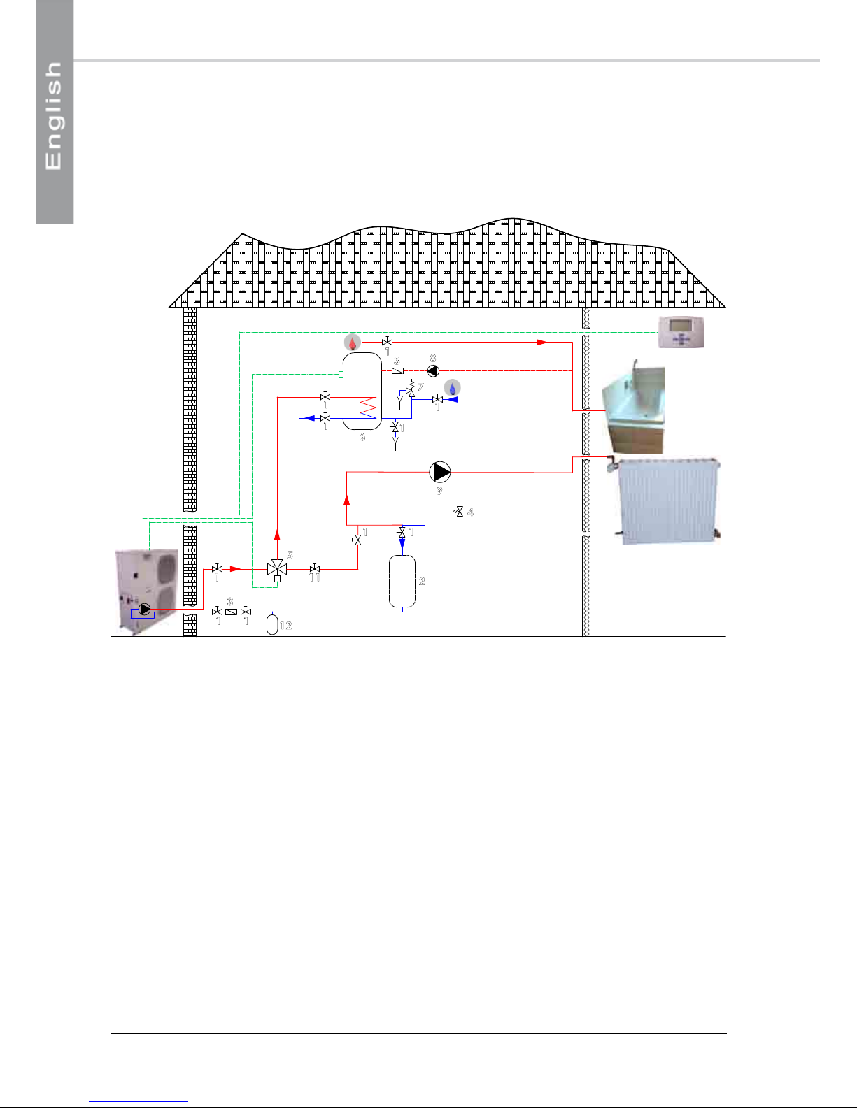
Layout 1: underfloor heating application without individual room regulation
This layout is recommended when the Aqu@Scop Advance DCI water flow is continuous and close to the nominal
value (no thermostatic valves).
The buffer tank (2) provides extra circulating water volume to maintain the minimum volume.
12.2. STANDARD CIRCUITS
1
3
2
1 1
1
1
11
3
1
5
6
7
8
1
1
12
1. Stop cocks
2. Buffer tank (optional)
3. Filter or sludge trap
4. Relief valve
5. 3-way valve – Domestic Hot Water
6. Domestic Hot Water tank
7. Safety devices
8. Recycling circulation pump (optional)
9. Circulation pump
10. Mixing tank
11. Flow regulating valve
12. Additional expansion tank (if required)
This drawing is not applicable to Aqu@Scop Advance DCI 16 if heating water circuit pressure drop
is higher than 20kPA.
12
Layout 2: underfloor heating application without individual room regulation
This layout is recommended for heating installations with wide operating water flow variations (radiator thermostatic
valves present in the system). We strongly recommend including the buffer tank (2) as it guarantees that the heating
loop capacity is higher than the minimum volume when the maximum number of thermostatic valves are closed.
The flow regulating valve (11) is used to balance the flow in heating mode and domestic hot water production
mode to always ensure optimum Aqu@Scop Advance DCI operation.
1
3
2
4
1 1
1
1
11
3
1
5
6
7
8
9
1
1
11
12

13
12.3. ANTI-FREEZE PROTECTION
We recommend that the installation is protected against freezing by adding anti-freeze.
The chart below indicates the concentration of anti-freeze to be used relative to the minimum outdoor temperature
reached.
Using untreated or inadequately treated water in this appliance can lead to a build-up of limescale,
algae or sludge deposits and cause corrosion and erosion. As the manufacturer is not aware of
the components used in the hydraulic network, or of the quality of water used, the installer or the
owner should contact a specialised water treatment company. This issue is particularly important
and every care should be taken to ensure that circuit water is properly treated in order to avoid
problems associated with incorrect water distribution. A clogged water network will systematically
lead to premature wear of the appliance's components.
Layout 3: radiator application or underfloor heating application with individual room regulation
This layout is also recommended for heating installations with wide operating water flow variations (radiator
thermostatic valves present in the system). Minimum system volume is guaranteed by a mixing tank (10). Take care
when calculating the volume of water in the installation and only take account of 50% of the mixing tank's volume.
Example: For a useful volume of 100 litres the actual mixing tank volume will be 200 litres.
The flow regulating valve (11) is used to balance the flow in heating mode and domestic hot water production
mode to always ensure optimum Aqu@Scop Advance DCI operation.
1
3
10
4
1 1
1
11
3
1
5
6
7
8
9
11
1
1
1
11
12
The mixture considerably alters the installation's performances, particularly in terms of pressure losses.
Concentration propylene glycol % 10 20 30
Minimum outdoor temperature °C -3 -7 -13
12.4. WATER TREATMENT WARNING

14
12.5. CONNECTION TO THE CENTRAL HEATING LOOP
You must check water tightness and the cleanliness of the installation before connecting the Aqu@Scop Advance DCI.
For the Aqu@Scop Advance DCI's WATER INLET and OUTLET connections, you must install manual stop
cocks with the same diameter as the main pipe work. This will enable maintenance work to be carried out on the
Aqu@Scop Advance DCI without having to bleed the entire system.
A link valve with pressure tap kit is available.
The Aqu@Scop Advance DCI must be protected by a water filter. Connect this subassembly to the water inlet
of the unit, taking care to maintain the strainer of the water filter downwards. A sludge trap should be fitted in the
event of high sludge build-ups.
WARNING!
Take care not to damage the hydraulic pipe links by applying too much tightening pressure.
Use a second wrench to compensate for the tightening torque.
You should always use a counter-wrench for tightening valves.
12.6. HEAT INSULATION
To guarantee proper energy efficiency and compliance with current standards, water pipes passing through
uninhabited zones should be properly lagged to retain heat.
To achieve correct insulation with conductivity of 0.04 W/mK, lag the pipes with insulating material with a radial
thickness between 25mm and 30 mm.
12.7. FILLING THE SYSTEM WITH WATER
All installation works must be completed and the system cleaned and drained, before filling the water circuit in
accordance with current best practices. The system should be filled to obtain a service pressure not exceeding 2.5
bars.
The water supply should come either from the mains network or from the Heat Pump or from any other point on
the installation.
Check that the automatic bleed valve operates correctly.
You must completely bleed the circuit of all air to ensure efficient operation.
Close the inlet water valve once the hydraulic circuit is filled correctly.
12.8. WATER FLOW CONTROLLER
A paddle type water flow controller is fitted to the water circuit connected to the condenser. The purpose of this
safety component is to ensure that a minimum water flow is established before the unit is started up.
The appliance is equipped with a set of safety devices including a safety valve set at 3 bars and a manual pressure
relief valve.
THE MANUFACTURER'S WARRANTY IS VOID IF THE FILTER SUPPLIED WITH THE
Aqu@Scop Advance DCI IS NOT INSTALLED TO PROTECT THE APPLIANCE

15
12.9. DETERMINING WATER FLOW
²P1 = Aqu@Scop Advance DCI outlet
water pressure.
²P2 = Aqu@Scop Advance DCI inlet water
pressure.
Reminder:
1bar = 100kPa = 10m water column
AVAILABLE PRESSURE = P1-P2
WATER FLOW CALCULATION GRAPH
Pump output (flow) is adjustable in relation to the system's pressure losses, by means of the internal pump speed
selector.
SEE APPENDIX
P1
P2
WATER
OUTLET
WATER INLET
(RETURN)
When you have measured the available pressure, expressed in
kPa, refer to the graph corresponding to the appliance installed
and read the flow value at the point where the pressure value
crosses the speed curve for the pump.
To ensure that the Aqu@Scop Advance DCI operates properly and to attain the required outlet water
temperatures, the water flow through the appliance has to be within specifications. The water flow through the
Aqu@Scop Advance DCI can be controlled and regulated by measuring the difference between:
²Both the outlet water and inlet water pressures.
12.9.1. METHOD BASED ON WATER
PRESSURES
12.9.2. WATER FLOW REGULATION

16
13. WIRING DIAGRAM AND LEGEND
N 776
13.1. WIRING DIAGRAM SEE APPENDIX
Connection to the QG main disconnect switch
230V +/-10% 50Hz
²L : phase
²N : neutral
²: ground
This supply comes from a CIRCUIT BREAKER or a FUSE HOLDER equipped with aM type fuses supplied by the
installer. Fuse sizes are indicated on the charts on the following page.
The appliance's electrical installation and wiring must comply with the country's current standards.
SE3870 Aqu@Scop Advance DCI 6 Control 1-Phase 230V +/-10% 50Hz
SE3869 Aqu@Scop Advance DCI 6 Power 1-Phase 230V +/-10% 50Hz
SE3872 Aqu@Scop Advance DCI 12/16 Control 1-Phase 230V +/-10% 50Hz
SE3871 Aqu@Scop Advance DCI 12/16 Power 1-Phase 230V +/-10% 50Hz
SE3888 Aqu@Scop Advance DCI R 6 Control 1-Phase 230V +/-10% 50Hz
SE3887 Aqu@Scop Advance DCI R 6 Power 1-Phase 230V +/-10% 50Hz
SE3884 Aqu@Scop Advance DCI R 12/16 Control 1-Phase 230V +/-10% 50Hz
SE3883 Aqu@Scop Advance DCI R 12/16 Power 1-Phase 230V +/-10% 50Hz
QG : Main cut-out switch
M1 : Compressor
FM1 : Internal safety device of the refrigeration
compressor
RV : 4-way cycle changeover valves
RAG : Anti-freezing protection electric resistance
FFC : Control circuit protection fuse
T1 : Ambience terminal 230/24V power supply
transformer
FER : Ferrite
LF : Supply filter
HF : Heater supply filter
CD : Compressor driver
CC : Coil
µPC : Controller
FFT : T1 transformer protection fuse (24V secondary
circuit)
EEV : Electronic pressure relief valve
ST1(EWT) : Entering water temperature
ST2(LWT) : Leaving water temperature
ST3(OCT) : Outdoor coil temperature
ST4(OAT) : Outdoor air temperature
ST5(CDT) : Compressor discharge temperature
ST6(CST) : Compressor suction temperature
ST8(DHWT) : Domestic hot water temperature (option)
ST9(DZLWT) : Dual-zone leaving water temperature
(option)
13.2. LEGEND
13.2.1. POWER SUPPLY
13.2.2. WIRING DIAGRAM KEY DESCRIPTIONS
13.2.2.1. POWER
13.2.2.2. COMMAND AND REGULATION

17
13.2.2.3. VENTILATION - FAN
13.2.2.4. WATER CIRCUIT
* These values are provided for information purposes only and must be checked and adjusted in relation to currently
applicable standards. They vary depending on the type of installation and the choice of conductors.
OF1 : Lower air exchanger fan motor
OF2 : Upper air exchanger fan motor
FOF1 : OF1 motor internal safety
FOF2 : OF2 motor internal safety
EP : Evaporating pressure transducer
HP1/2 : Automatic reset high pressure switch
CF : Fan motor speed controller
K2 : Start-up relay
COF1: OF1 motor capacitor
COF2: OF2 motor capacitor
KOF1 : OF1 fan motor relay
KOF2 : OF2 fan motor relay
FS : Water flow switch
WP : Water pump
KWP : WP water pump relay
CWP : Water pump capacitor
FFEH1 : Power circuit protection fuse (stage 1)
FFEH2 : Power circuit protection fuse (stage 2)
KEH1 : Heater element power relay (stage 1)
KEH2 : Heater element power relay (stage 2)
FCM : Heater safety device with manual reset
FCA : Heater safety device with automatic reset
KFCM: Power cut-off contactor (controlled by the "safety
device with manual reset")
EH : Heater elements
EMH : Back-up heating switch
Supply voltages 230V +/-10% 50Hz
Aqu@Scop Advance DCI Aqu@Scop Advance DCI R
6 12 16 6 12 16
General protection fuse rating aM type
(not supplied) 40A 63A 63A 25A 32A 32A
Fuse ratings
FFC aM type 4A 4A 4A 4A 4A 4A
FFEH1 Gg type 10A 10A 10A / / /
FFEH2 Gg type 10A 20A 20A / / /
FF T type T 0.6A 0.6A 0.6A 0.6A 0.6A 0.6A
Contactors and power relays
KFCM 12A 12A 12A / / /
K5 30A 30A 30A / / /
K6 30A 30A 30A / / /
WP2 : Water pump N°2
DHWV : Domestic hot water valve
DHWEH : Domestic hot water electric heater
DHWWP : Domestic hot water pump
DZWP : Dual-zone water pump (zone 1)
BOILER : Hot water boiler
BRV : Boiler relief valve
ON/OFF : Remote ON/OFF switch
DAY/NIGHT : DHW off-peak hours switch
EJP : Off-peak days switch
13.2.2.5. ELECTRIC HEATER
13.2.2.6. OPTIONS
13.2.3. FUSE VALUES, NOMINAL CURRENT OF CONTACTORS AND POWER RELAYS

18
14. ELECTRICAL CONNECTIONS
WARNING
Before carrying out any work on the equipment,
make sure that the electrical power supply is
disconnected and that there is no possibility
of the unit being started inadvertently.
Non-compliance with the above instructions
can lead to injury or death by electrocution.
The electrical installation must be performed by a fully qualified electrician, and in accordance with local electrical
standards and the wiring diagram corresponding to the unit model.
Any modification performed without our prior authorisation may result in the unit’s warranty being declared null
and void.
The power supply cable section must be sufficient to provide the appropriate voltage to the unit’s power supply
terminals, both at start-up and under full load operating conditions.
The power supply cable shall be selected in accordance with the following criteria:
1. Power supply cable length.
2. Maximum unit starting current draw – the cables shall supply the appropriate voltage to the unit
terminals for starting.
3. Power supply cables’ installation mode.
4. Cables’ capacity to transport the total system current draw.
Short circuit protection shall be provided. This protection shall comprise fuses or circuit breakers with high breaking
capacity, mounted on the distribution board.
If the local control includes a remote ambient terminal, it shall be connected with shielded cable and shall not
pass through the same conduits as the power supply cables as the voltages induced may create reliability faults in
the unit’s operation.
WARNING!
On-site wiring must be performed in accordance with the wiring diagram present in the appliance's
electrical connection box.
Mains power supply cables to the appliance must have copper conducting cores and be sized in
compliance with currently applicable IEC standards.
The installer must make sure that the installed power, the amperage and type of the protections and
the cross-section of the cables are sufficient to avoid an overload, and tripping of the installation
to protection mode.
The appliance must be grounded via a terminal block located inside the electrical connection box.
The power supply must not fluctuate by more than 10 %.
This manual suits for next models
2
Table of contents
Popular Heat Pump manuals by other brands

Nova Booster
Nova Booster Swimming Pool Heat Pump User & service manual

Electra
Electra PXD 25 DCI Service manual

Daikin
Daikin EHVZ08S18DA6V7 installation manual

Glen Dimplex
Glen Dimplex LIK 8TES Installation and operating instruction

Ingersoll-Rand
Ingersoll-Rand ENL 5 Instructions for installation and operation

Bryant
Bryant EVOLUTION V 288BNV owner's manual


SH13 Installation and maintenance instructions")


