Aqua Comfort XL Series User manual

844.770.HEAT • www.AquaComfort.com
XL Series Heat Pump Pool Heater
INSTALLATION MANUAL

Table of Contents
Inspection 2
Safety Consideration 2
General Information 3
Installation Location & Clearances 5
Water Flow & Connections 8
Electrical Connections 12
Wiring Diagram 13
Connecting to Automated System 14
Automated System Diagram 15
Start Up 15
Electronic Control Panel 16
Mode of Operation 22
Maintenance 27
Winterizing 27
Troubleshooting 28
Requesting Service 30

Inspection
Immediately upon receipt, inspect cartons and their contents for damage due to transit.
Damage, if found, should be noted on delivery papers and a claim led with the carrier.
Also check the unit data plate to make sure you have the proper model before installing.
Damage incurred during shipping is not covered under AquaComfort Solutions warranty.
Safety Consideration
• For personal safety, and to avoid damage to equipment, follow all safety instructions
displayed on the equipment and within this manual. Repair and service of heat pump
must be performed by an authorized service center.
• Warranties may be voided if the equipment has been
improperly installed, maintained or serviced.
• If service is deemed necessary, please contact AquaComfort Solutions Technical Support.
When installing and using your heat pump basic safety precautions
must always be followed, including the following:
WARNING: Failure to heed the following may result in injury or death.
• Installation and repairs must be performed by a qualied technician.
• The heat pump contains refrigerant under pressure. Repairs to the refrigerant
circuit must not be attempted by untrained and/or unqualied individuals.
Service must be performed only by qualied HVAC technicians.
• Recover refrigerant before opening the system.
• The heat pump utilizes high voltage and rotating equipment. Use caution when servicing.
• Electrical installation and service should be performed by a Licensed Electrician only.
• Improper water chemistry can present a serious health hazard. To avoid possible
hazards, maintain pool / spa water per standards detailed in this document.
• Prolonged immersion in water warmer than normal body temperature may cause Hyperthermia.
– The symptoms of Hyperthermia include unawareness of impending hazard, failure to perceive heat,
failure to recognize the need to exit the spa, and unconsciousness. The use of alcohol, drugs, or
medication can greatly increase the risk of fatal Hyperthermia. In addition, persons having an adverse
medical history, or pregnant women, should consult a physician before using a hot tub or spa. Children
and the extreme elderly should be supervised by a responsible adult.
• Prolonged immersion in water colder than normal body temperature may cause Hypothermia.
– The symptoms of Hypothermia include shivering (although as hypothermia worsens, shivering stops),
clumsiness or lack of coordination, slurred speech or mumbling, confusion and poor decision-making,
drowsiness or low energy, lack of concern about personal welfare, progressive loss of consciousness,
weak pulse and slow or shallow breathing. In addition, persons having an adverse medical history, or
pregnant women, should consult a physician before immersing in a cold body of water. Children and
the extreme elderly should be supervised by a responsible adult.
CAUTION - Failure to heed the following may result in equipment damage.
• Maintain proper water chemistry in order to avoid damage to pump, lter, pool shell, etc.
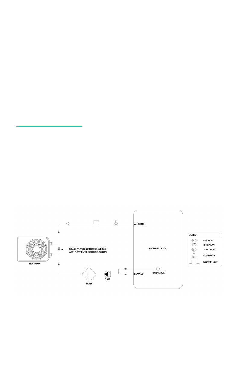
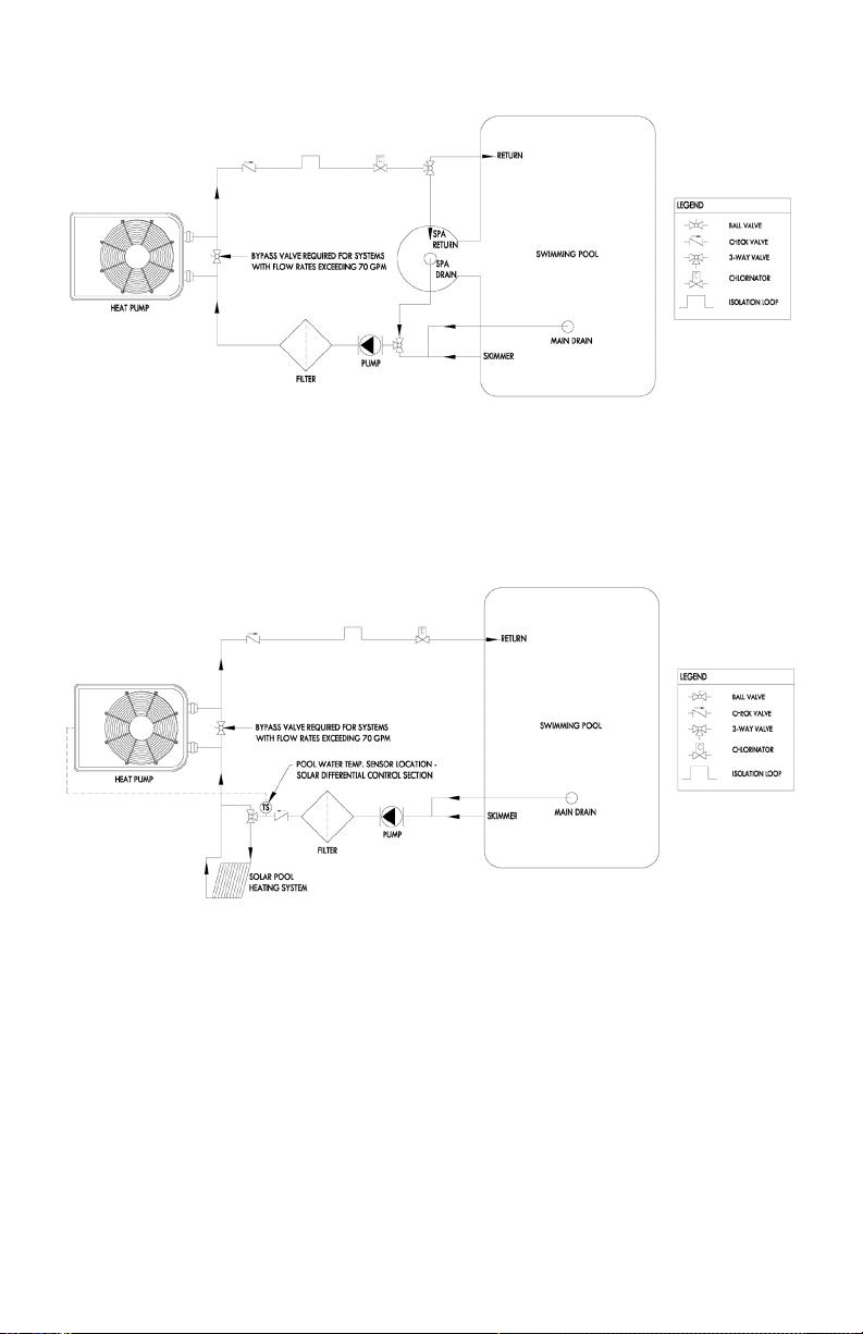
• Water ow exceeding maximum ow rate requires a bypass.
Damage due to excessive water ow will void warranty.
ACS XL Heat Pump Pool Heater Installation Manual 2

General Information
The information in this manual was prepared to assist in the proper installation,
operation, maintenance and service of your new heat pump pool heater.
Please read the entire manual and follow all instructions. Improper installation
and use can result in damage to the heat pump, unsatisfactory operation and
performance, and may void the warranty. Retain this manual for quick reference.
MODEL SPECIFICATIONS
3
Heat Only
Model ACT-750 ACT-1100 ACT-1250 ACT-1500 ACT-1750
Compressor SCROLL SCROLL SCROLL SCROLL SCROLL
Minimum Breaker Size 20 30 40 40 50
Voltage / Hertz / Phase 230 / 60 / 1 230 / 60 / 1 230 / 60 / 1 230 / 60 / 1 230 / 60 / 1
Water Flow (gpm) 15 - 50 20 - 70 20 - 70 20 - 70 20 - 70
Dimensions (L x W x H) 28 x 28 x 26 39 x 30 x 32 39 x 30 x 32 39 x 30 x 32 39 x 30 x 32
Shipping Weight (lbs) 170 240 240 250 290
Recommended clearance access on service side is 24” and 18” on other three air intake sides.
Recommended minimum over head (top of unit) clearance is 48”.
HeatCOOL
Model ACT-1100HC ACT-1250HC ACT-1500HC ACT-1750HC
Compressor SCROLL SCROLL SCROLL SCROLL
Minimum Breaker Size 30 40 40 50
Voltage / Hertz / Phase 230 / 60 / 1 230 / 60 / 1 230 / 60 / 1 230 / 60 / 1
Water Flow (gpm) 20 - 70 20 - 70 20 - 70 20 - 70
Dimensions (L x W x H) 39 x 30 x 32 39 x 30 x 32 39 x 30 x 32 39 x 30 x 32
Shipping Weight (lbs) 250 250 260 300
Recommended clearance access on service side is 24” and 18” on other three air intake sides.
Recommended minimum over head (top of unit) clearance is 48”.

4ACS XL Heat Pump Pool Heater Installation Manual
FIGURE 2: HEAT PUMP DIMENSIONAL DRAWINGS
FIGURE 1: HEAT PUMP WATER CONNECTION TEMPLATES

Installation Location & Clearances
When selecting a location consider the following:
• Heat pump must be located outdoors. Unit is not rated for indoor use
and will not operate to specications.
• The heat pump should sit on a solid level surface sufciently above grade to prevent water
from entering it, and to allow condensate to drain from the base. Some locations require
specic anchorage requirements. See later sections in this manual for further details.
• The length of water piping and electrical conductors should be kept
as short as possible to avoid capacity loss and decreased efciency.
• The heat pump can produce a large amount of water in the form of condensation.
The amount of water depends on air temperature and humidity. Plan for water
drainage disposal as needed.
• Irrigation water may damage heat pump components.
Have irrigation water directed away from the heat pump.
• The heat pump will withstand normal rainfall. Do not allow a roof slope to direct
rainwater onto the heat pump. Have a gutter installed on the roof edge to direct
this water away from the heat pump or install the heat pump in another location.
MOUNTING PAD REQUIREMENTS
• Build the heat pump pad out of concrete or another code-approved material.
• Conrm the pad can support the weight of the heat pump.
See Model Specications table in previous section.
• Elevate the pad enough to allow for drainage.
• Make sure the pad is at and level.
• Have the pad extend at least 6 inches from the heat pump base in all directions.
• Do not install the heat pump on soil or grass.
• Do not allow the heat pump base to touch the buildings foundation.
• Do not place the heat pump directly on a concrete oor inside a building. This can cause
noisy equipment vibration. Install vibration dampeners between the heat pump base and oor.
• Equipment pad must meet all requirements of authorities having code-related jurisdiction
ANCHORING THE HEAT PUMP
• Follow all applicable local, state, and national requirements regarding wind load anchoring.
• If required by local building code and/or AHJ, AquaComfort Solutions offers a Hurricane/
Seismic Clip Kit to anchor the heat pump pool heater to a code-approved concrete pad.
• See anchorage requirements in Engineering Report ACS-ENG-001.
5

FIGURE 3.1: HURRICANE CLIP INSTALLATION DETAIL
FIGURE 3.2: HURRICANE CLIP ANCHOR LAYOUTS
6ACS XL Heat Pump Pool Heater Installation Manual

7
FIGURE 4: HEAT PUMP CLEARANCES
CLEARANCES
• Proper air ow is required for the heat pump to operate efciently. Avoid
placing objects near or on top of the heat pump. This includes shrubbery
and lawn furniture. These objects will also hinder maintenance access.
• Avoid storing corrosive chemical containers near the heat pump.
Certain chemicals can cause equipment damage & premature failure.
• Minimum of 36” of clearance on access/service side of heat pump.
• Minimum of 18” of clearance on all three air intake sides of heat pump.
• Minimum of 48” of clearance for air discharge (top of unit). For optimal
performance it is recommended that nothing is above the top of the unit.

Water Flow & Connections
Water connections are made at the rear of the heat pump opposite the control panel. Water “in”
and “out” are labeled at the connections. Unions are supplied and are made to accept either 2”
or 1 ½” rigid PVC pipe. See Model Specications table (page 3) for required ow rates.
NOTE: Unions can be used for quick drainage of your heat pump and winterizing.
• Heat pump must be piped downstream from the lter in the pool return line.
• When all the plumbing connections are complete, and ample drying time is allowed for
the glued connections, run the lter pump and check the entire system for water leaks.
• Make sure lter is clean and there are no obstructions in the ltering system.
• Proper water ow is essential to the performance of the heat pump.
• The minimum ow rate is 20 GPM.
• Use proper PVC cleaner, PVC glue, and proper gluing
techniques when making PVC pipe connections.
PLUMBING REQUIREMENTS
CAUTION - Failure to heed the following may result in equipment damage.
• Do not use glue on the threaded portion of the equipment’s unions.
Gluing a union in place will prevent the ability to service or winterize the unit.
• The heat pump must receive water ow within the specied ranges in all conditions.
Water ow exceeding maximum ow rates may damage heat pump and will not be
covered under equipment warranty. See Model Specications table (page 3) in previous
section for water ow rate ranges based on unit.
8ACS XL Heat Pump Pool Heater Installation Manual
FIGURE 5.1: SINGLE HEAT PUMP & POOL

9
FIGURE 5.2: SINGLE HEAT PUMP, POOL & SPA
FIGURE 5.3: SINGLE HEAT PUMP & POOL WITH SOLAR POOL HEATING SYSTEM

FIGURE 5.4: SINGLE HEAT PUMP & POOL WITH GAS HEATER
FIGURE 5.5: MULTIPLE HEAT PUMPS & POOL
10
ACS XL Heat Pump Pool Heater Installation Manual

11
IN-LINE CHLORINATORS
• In-line chlorinators must be placed downstream of the
heat pump pool heater as low to the ground as possible.
• The plumbing placed between the chlorinator and heat pump must be done in a way
to isolate chemical concentrations from entering the heat pump when the pool’s lter
pump is off. The isolation loop method shown in Figure 6 is one method to achieve this.
• Failure to isolate high concentrations of chemicals in the water from
entering the heat pump pool heater will damage the heat exchanger.
FIGURE 6: ISOLATING IN-LINE CHLORINATOR

12ACS XL Heat Pump Pool Heater Installation Manual
Electrical Connections
• Field connections must comply with NEC and local electrical codes,
(i.e. CSA C22.1 or NFPA70.) The work must be done by a qualied electrician.
• The heat pump must be permanently grounded and bonded. Bonding will drastically
reduce the chances of electrolysis (Electrical Corrosion) due to dissimilar metals.
• Use copper conductors only.
DANGER: Disconnect all power sources before performing any work on unit.
• Standard Power Supply: 230Volts – 60Hertz – 1Phase.
• See unit data plate for specic ampacity.
WIRING THE MAIN POWER SUPPLY
1. Remove the screws from lower left and right side of front cover (service panel).
2. Remove the screws on left side of the hinged electrical enclosure.
3. Route weather tight, exible conduit through opening at base of unit.
4. Connect conduit to bottom of the electrical enclosure using a weather tight tting. A 1.13” hole
is provided near the main contactor to accept a weather tight tting. Mounting conduit directly to
the electrical enclosure will ensure a moisture tight seal, thus extending the life of the heat pump.
Attach grounding conductor to the ground lug provided inside the electrical enclosure (labeled).
5. Install L1 and L2 input conductors to the line side of the main contactor. (See wiring diagrams.)
Ensure that the wires are inserted properly into the contactor connecting lugs and that the
screws are properly torqued. Torque lugs to 40 in-lbs. Burnt/failed contactors due to poor
eld wiring is NOT covered under warranty!
6. Connect bond wire (at least #8 solid copper wire) to bond lug provided on right or left
side of coil header plate to pool pump bonding terminal or other suitable location.
FIGURE 7: MAIN POWER SUPPLY

13
Wiring Diagram
1. Use copper conductors only.
2. Connect eld wiring in grounded rain tight conduit, per rating plate.
3. Connect bond wire to pool steel using # 8 solid copper wire or larger.
4. All wiring must conform to National (N.E.C.) and local electrical codes.

14ACS XL Heat Pump Pool Heater Installation Manual
Connecting to Automated System
Wiring External Controls and Remotes For Heating Control:
NOTE: When connecting remotes and external controls to the main control within the electrical
enclosure, conduit must be used within the enclosure to ensure a denite separation of factory
wiring/circuits and external control wiring. When installed ensure that there is no transmission
of stress to main control wire terminal connections.
1. Route control wires through .875” hole provided in bottom of electrical panel.
2. Route control wires to the circuit board.
3. Connect control wiring to the POOL / SPA connection at the bottom right of control board.
See page 15 for diagram showing location on Board.
4. See Below (Remote Thermostats and Controllers: Controlling in Heating)
REMOTE THERMOSTATS AND CONTROLLERS (Controlling a Heat only Model)
If a remote thermostat or any other control system is to be used to turn the heat pump
on and off, a normally open dry contact connection can be made at the terminals labeled
POOL/SPA on the bottom right of the electronic control board. In the case of a remote
thermostat where the temperature will be regulated externally, set the “POOL” mode to the
OFF position and the “SPA” mode to 104º F (40º C). The heat pump will only run when the
remote control calls for heating (circuit closed).
When the heat pump is being told to turn on by the
Automated system, it will switch into “SPA” mode.
This does not mean it has changed how it heats but simply that “SPA” mode
is the mode that is enabled for Automated system control in heating.
CONTROLLING A HeatCOOL MODEL WITH AN AUTOMATED SYSTEM
If a remote thermostat or any other control system is to be used to turn a Heat/Cool unit
on and off, rst go to the pool mode set point temperature. This is accomplished by pushing
the hand (settings) button multiple times until you see “POL” on the display. As soon as the
display shows this, press the up arrow multiple times until the set point temperature is at 90.
In order for the cooling feature to work while the unit is connected to an automated system,
the unit must be set to auto mode. To do this push the hand button multiple times until you see
“PHC” in capital letters on the display. As soon as you see this press the up arrow multiple times
until “AUt” is displayed on the unit. The LED next to the word Pool will no longer be illuminated.
The nal setting you must do in order for the heat/cool unit to work properly with the
automated system is set the SPA set point temperature to 104. To do this, press the hand
button multiple times until the display reads “SPA” and then immediately press the up arrow
multiple times until you reach 104. Once that is done the unit should be ready to be controlled
by the automated system.
When the HeatCOOL unit is being told to turn on by the Automated system, it will switch
into “SPA” mode. This does not mean it has changed how it heats but simply that “SPA”
mode is the mode that is enabled for automated system control in heating.

15
Automated System Wiring Installation Diagram
Start Up
ON/OFF MODE
When in OFF Mode the display will show actual water temperature for six seconds and then
display “OFF” for two seconds. When the unit is set to “ON”, it will show the actual water
temperature for six seconds and then show “HEA” for two seconds. To switch the unit from
“off” to “on”, Press the SELECT KEY until you reach “OFF”. Then immediately press the
down arrow twice. The display should read on in lower case letters. To switch the unit from
on to off, Press the SELECT KEY until you reach “OFF”. Then immediately press the up
arrow twice. The display should read “OFF” in lower case letters.
NOTE: Some units will have a power button ( ) on the control board.
Pressing this simply turns the unit on or off with one press.
NOTE: The fan may take 3-5 minutes to start after pressing the power button.

16ACS XL Heat Pump Pool Heater Installation Manual
Electronic Control Panel
The control panel will display the actual Pool or Spa water temperature for six seconds and then
display the mode of operation that it is currently in (HEA, COL, AUt or OFF) for two seconds.
MENU OPTIONS
The unit will be factory preset as follows:
• Heat only unit: Will be programmed in “Pool mode (POL)”
to “heat” and set to desired temperature of 82°F.
• Chill only unit: Will be programmed in “Pool mode (POL)”
to “cool” and set to desired temperature of 87°F.
• Heat/Cool unit: Will be programmed in “Pool mode (POL)”
to “auto” and set to desired temperature of 87°F.
FACTORY SELECT MENU
Select Menu Setting POL SPA SSP P_S PHC
Default Setting 85 85 82 dIS P_H

17
Pool Mode Set Point:
When SELECT button is pressed the control displays pool set point screen “POL”
• The set point is raised by pressing the UP button up to desired temperature.
(95°F, 35°C maximum)
• The set point is lowered by pressing the DOWN button down to 61 (61°F, 10°C).
When DOWN button is pressed again then “OFF” will be displayed.
• The set point is adjusted faster by holding pressed UP or DOWN button.
Spa Mode Set Point:
When SELECT button is pressed again after POL is displayed
the control displays spa set point screen “SPA”
• The set point is raised by pressing the UP button up to desired temperature.
(104°F, 40°C maximum)
• The set point is lowered by pressing the DOWN button down to 61 (61°F, 16°C)
When DOWN button is pressed again then “OFF” is displayed.
• The set point is adjusted faster by holding pressed UP or DOWN button
Solar Mode Set Point
This feature shows only when enabled in Conguration menu.
When SELECT button is pressed again after SPA is displayed the control
displays spa set point screen “SSP”
• The set point is raised by pressing the UP button up to 105 (105°F, 41°C)
• The set point is lowered by pressing the DOWN button down to 61 (61°F, 16°C).
The value for SSP may be equal to or greater than the value for POL but not
lower when operating in pool mode. The value for SSP may be equal to or
greater than the value for SPA but not lower when operating in spa mode.
• The set point is adjusted faster by holding pressed UP or DOWN button
Pool vs. Spa Mode Selection
When SELECT button is pressed again after SPA or SSP display
then shows Pool vs. Spa mode screen is, “P_S”
• Pool mode is selected by pressing UP button
• Spa mode is selected by pressing DOWN button
• Note this will be overridden by the remote pool spa switch.
Pool Heat vs. Cool Mode Selection
This feature shows only when enabled in Conguration menu.
When SELECT button is pressed after P_S display the control displays
pool heat vs. cool mode screen “PHC”
• With UP button user sets the Pool Heat mode, “P_H”
• With DOWN buttons user sets the Pool Cool mode, “P_C”
• With either UP or DOWN buttons a second time user sets the Auto mode, “AUt”.
This is set for heat-cool units to automatically switch between heating and cooling.

18ACS XL Heat Pump Pool Heater Installation Manual
FACTORY SELECT MENU CHART

19
FACTORY CONFIGURATION MENU
The service menu is entered by a serviceman by pressing UP and DOWN buttons simultaneously
for 5 seconds. The screens and settings within the service menu are shown below.
User advances from one screen to another and goes in circles by pressing Select button.
Temperature Scale Selection (Fahrenheit vs. Celsius):
When the unit enters Service Menu display will read F_C. Or if the SELECT button is
pressed again after setting DEL. This is for temperature scale selection displayed in
Fahrenheit or Celsius. The Fahrenheit scale, “°F” is selected by pressing the UP button
or the Celsius scale, “°C” is selected by pressing the DOWN button. Factory default is F.
Pool Cool Mode Selection Enable/Disable:
When SELECT button is pressed again after F_C then display reads P_C.
This feature is enabled (EnA) by pressing the Up button or disabled (dIS)
by pressing the DOWN button. Factory default is dIS.
Solar Mode Selection Enable/Disable:
When SELECT button is pressed again after P_C then display reads SLR.
This feature is enabled (EnA) by pressing the UP button or disabled (dIS)
by pressing the DOWN button. Factory default is dIS.
Water Temperature Reading Calibration:
When SELECT button is pressed again after SLR then the display reads tSC.
This feature is used to adjust the reading calibrated of the water temperature
+/-5°F (+/-3°C). The control will show the water temperature reading plus
calibration setting when is in normal operating screen. Factory default is 0.
Evaporator Temperature Reading Calibration:
When SELECT button is pressed again after tSC then the display reads dSC. This feature
is used to adjust the reading of the evaporator temperature +/-5°F (+/-3°C). The control will
show evaporator temperature reading plus calibration setting when the SELECT and UP
buttons are held for 5 seconds. The control will revert back to the water temperature after
5 seconds of viewing the evaporator temperature. Factory default is 0.
Solar Temperature Reading Calibration:
When SELECT button is pressed again after dSC then the display reads sSC. This feature
is used to adjust the reading of the solar temperature +/-3°F (+/-2°C). The control will show
solar temperature reading plus calibration setting when the SELECT and DOWN buttons are
held for 5 seconds. The control will revert back to the water temperature after 5 seconds of
viewing the evaporator temperature. Factory default is 0.
Conguration
Menu Setting F_C P_C SLR S_t tSC dSC sSC db SDS SDO dEF dEL
Default Setting °F dIS dIS dIS 0 0 0 2 6 3 AIr 0
Other manuals for XL Series
1
This manual suits for next models
9
Table of contents
Other Aqua Comfort Swimming Pool Heater manuals
Popular Swimming Pool Heater manuals by other brands

Hayward
Hayward H150FD Service & installation manual

Pentair
Pentair 200K BTU/HR Installation and user guide

Raypak
Raypak VERSA 185B Replacement parts

Hayward
Hayward ENP2M-9A Installation instructions manual

Pentair
Pentair MASTERTEMP 200 HD Installation and user guide

Blue Lagoon
Blue Lagoon ProfiHeater 1kW manual

Steinbach
Steinbach 049100 instruction manual

Sun2Solar
Sun2Solar 805401 Installation and operation manual

Dickinson
Dickinson NEWPORT operating instructions

AZURO
AZURO PASRW015-P-AI installation manual

Climate Technologies
Climate Technologies Vulcan HE 300M operating instructions

GAME
GAME SolarPRO XD3 owner's manual