Product Manual Omnia Hand Dryer Product Manual Omnia Hand Dryer
2 of 7 Revision 01 3 of 7 Revision 01
SAFETY INSTRUCTIONS
Before to carry on any operation, please read carefully and take into account the following safety in-
structions:
• Only a qualified technician can install, adjust and maintain this device. All these operations must be
always done according to the current legal European Standards of installation and according the local
installation regulations as well.
• Be careful when the casing of the appliance is dismantled because active parts of the device become ac-
cessible and then there is a potential risk of an electric shock.
• Before any electrical manipulation, the electrical current must be cut in order to avoid any electric shock
risk.
• The installer must ensure that the appliance is earthed in accordance with the regulations in force.
• This appliance can be used by children aged from 8 years and above and persons with reduced physical,
sensory or mental capabilities or lack of experience and knowledge if they have been given supervision or
instruction concerning use of the appliance in a safe way and understand the hazards involved. Children
shall not play with the appliance. Cleaning and user maintenance shall not be made by children without
supervision.
• The device could not be installed on a normally inflammable surface.
• To fix the hand dryer to the wall follow the instructions of this manual and use the template provided with
the device as well. To fix the machine with adhesives or similar methods is forbidden.
PRIOR TO INSTALLATION
Location
• The Wash & Dry hand dryers from AquaDesign are supplied with 51 inch hose on the OMD, the ‘motor
unit’ must be placed within the hose length to the ‘air unit’..
Basin / Deck
• The basin or deck shall allow a hand dryer installation according to the present installation manual.
• The basin/deck must have a minimum depth of 4-3/4”, vertical walls and not so rounded edges in
order to avoid splashing on the user.
Spacing
• The on-center distance to the Omnia water faucet should be at
least 5-1/2”
5-1/2”
INSTALLATION
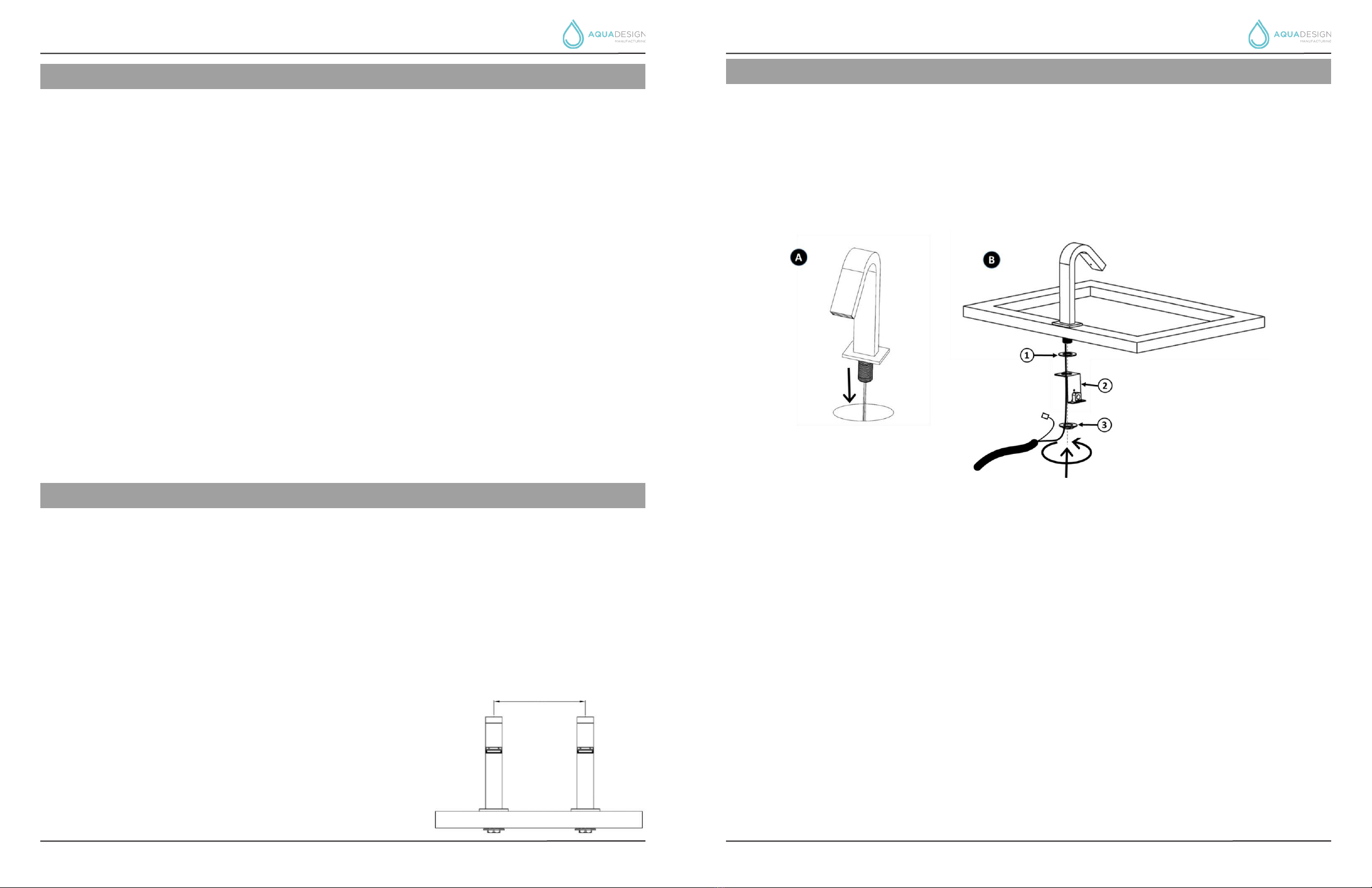
SPOUT INSTALLATION
• Drill a 1-1/8” - 1-3/8”mm hole on the basin/deck if it is not already drilled.
• (A) Place the ‘air unit’ in the hole, inserting the IR sensor wire in advance.
• (B) Firmly hold the ‘air unit’ to ensure a correct placement, insert the rubber gasket (1), the metal plate
(2) and tighten the fixing nut (3).
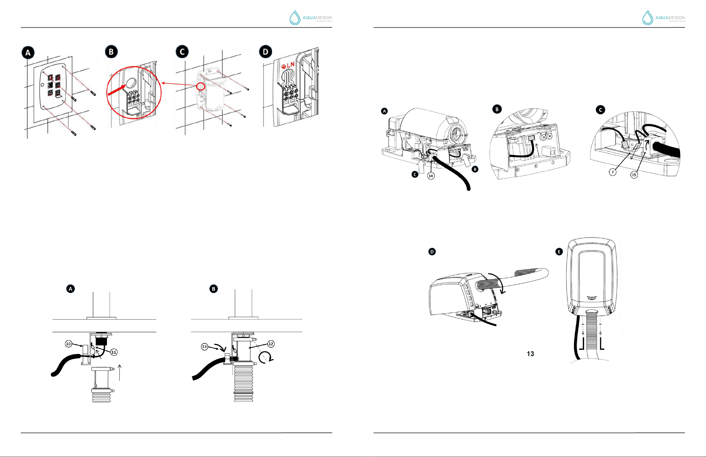
ENGINE INSTALLATION
• Carefully remove the casing since it is connected to the base by a tab that joins the two pieces (cas-
ing and base) at the rear. Remove the casing keeping it at an angle at all times (Figure 3) until the up-
per tab is completely withdrawn, taking care to not damage the internal components, in particular the
electronic circuit, and not damage the surface of the casing.
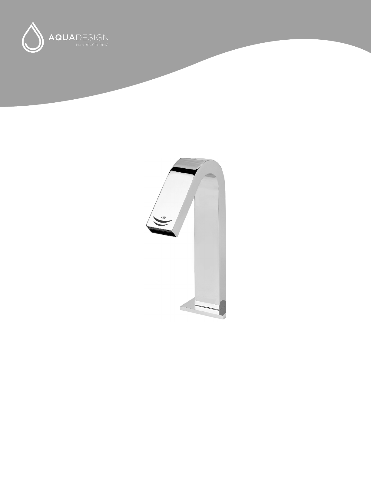
• -A) Make four drill holes with an 8 mm (0,31”) diameter in the wall, using the provided template.
• (B) Pass the electrical cables from the power grid through the hole with the 22 mm (0,87”) diameter
which is situated above the device’s terminal strip.
• (C) Firmly screw the base of the device to the wall, ensuring that the 4 silent- blocks are correctly
placed between the base and the wall.
• (D) Connect the electrical cables to the hand dryer’s terminal strip. Connect the cables corresponding
to the two phases (N and L) and to earth in the corresponding sockets of the terminal strip, as indi-
cated by the engraved letters.