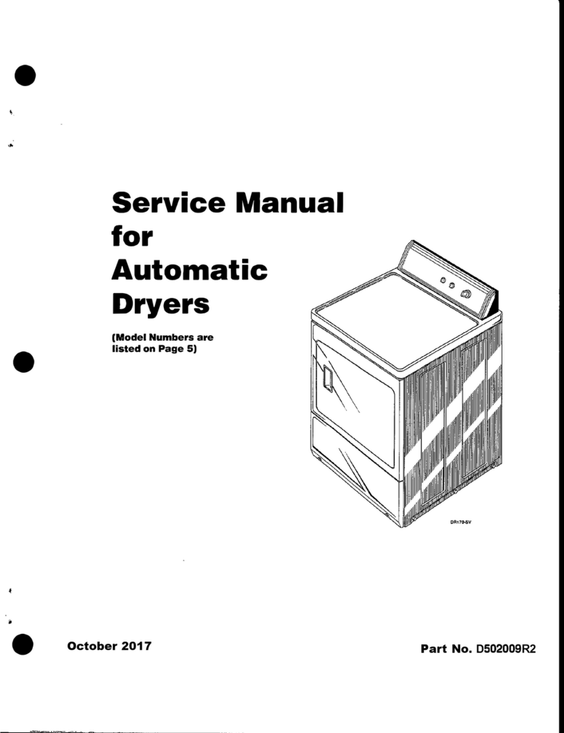
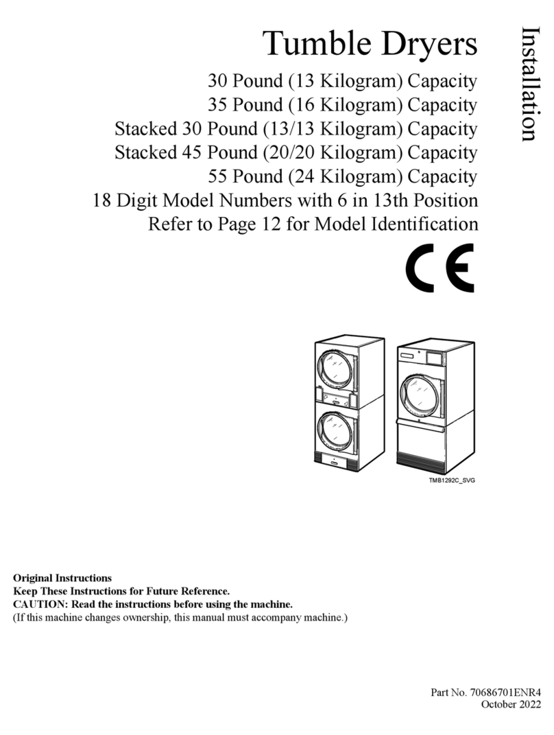
ALLIANCE T30 Series Programming manual

www.alliancelaundry.com
Troubleshooting
Part No. 70291301R3
December 2016
Tumble Dryers
30 Pound Stack
Through Serial No. 0602004143
Refer to Page 5 for Model Numbers
START
25
C
HIGH
TEMP
MED
TEMP
LOW
TEMP
NO
HEAT
123
SELECT
TEMP INSERT
COINPUSH
START
123
SELECT
TEMP INSERT
COINPUSH
START
START
25
C
HIGH
TEMP
MED
TEMP
LOW
TEMP
NO
HEAT
T464PZ3A


© Copyright 2016, Alliance Laundry Systems LLC
All rights reserved. No part of the contents of this book may be reproduced or transmitted in any form or by any means without
the expressed written consent of the publisher.
70291301 1
© Copyright, Alliance Laundry Systems LLC – DO NOT COPY or TRANSMIT
Table of
Contents
Section 1 – Safety Information ...............................................................5
Locating An Authorized Service Person...............................................6
Safety Warnings and Decals..................................................................7
Safety Precautions for Servicing Tumble Dryers..................................7
Section 2 – Introduction..........................................................................8
Model Identification..............................................................................8
Serial Plate Location..............................................................................9
Customer Service...................................................................................9
Wiring Diagram.....................................................................................9
How A Tumble Dryer Works..............................................................10
Section 3 – Troubleshooting..................................................................11
1. Tumble Dryer Does Not Start.....................................................12
2. Motor Does Not Start..................................................................13
3. Motor Overload Protector Cycles Repeatedly............................14
4. Motor Runs But Cylinder Does Not Turn...................................15
5. Motor Does Not Stop..................................................................16
6. Burner Does Not Ignite...............................................................17
7. Burner Ignites and Goes Out Repeatedly....................................20
8. Burner Does Not Shut Off ..........................................................21
9. Clothes Do Not Dry ....................................................................22
10. Tumble Dryer Overheating.........................................................24
11. Burner Not Burning Properly......................................................25
12. Loading Door Opens During Operation......................................26
13. Cylinder Continues to Spin with Door Open..............................27
14. Coin Does Not Fall into Coin Vault or Coin Drop Sensor
Does Not Register That Coin Has Been Entered........................28
Section 4 – Adjustments........................................................................31
15. Troubleshooting and Cleaning Coin Drop..................................31
16. Troubleshooting Coin Drop........................................................31
17. Cleaning Coin Drop ....................................................................31
Section 5 – Electronic Control Troubleshooting.................................35
18. Theory of Operation of Instant Electronic Ignition ....................35
19. Cannot Perform Infrared (IR) Communication...........................36
20. Coins Ignored When Entered......................................................37
21. Control Display – Door Open Light “On”..................................38
22. Control Display – “door” Error on 25, 30, Stacked 30 and
35 Pound Tumble Dryers with 24 Volt EDC Controls...............39
23. Control Display – No Visible Display – OPL Microprocessor
Models.........................................................................................40
24. Control Display – No Visible Display – Power On....................41
25. Will Not Start – Electric – Manual Timer...................................42
26. Will Not Start – Electric – Rotary Coin Drop.............................43
27. Will Not Start – Gas – Manual Timer.........................................45
28. Will Not Start – Gas – Rotary Coin Drop...................................46

270291301
© Copyright, Alliance Laundry Systems LLC – DO NOT COPY or TRANSMIT
29. Will Not Start – Steam – Manual Timer.....................................48
30. Will Not Start – Steam – Rotary Coin Drop...............................49
31. Will Not Start/Continue Running – EDC Control......................51
32. Will Not Start/Continue Running – OPL Microprocessor
Control ........................................................................................54
33. Will Not Run – Electric – Manual Timer ...................................57
34. Will Not Run – Electric – Rotary Coin Drop..............................60
35. Will Not Run – Gas – Manual Timer..........................................63
36. Will Not Run – Gas – Rotary Coin Drop....................................65
37. Will Not Run – Steam – Manual Timer......................................67
38. Will Not Run – Steam – Rotary Coin Drop................................69
39. Will Not Heat – Electric – Manual Timer...................................71
40. Will Not Heat – Electric..............................................................73
41. Will Not Heat – Electric – Rotary Coin Drop (With and
Without Time Delay Board) .......................................................75
42. Will Not Heat – Electric/Gas – OPL Microprocessor.................77
43. Will Not Heat – Gas – EDC Models...........................................80
44. Will Not Heat – Gas – Manual Timer.........................................82
45. Will Not Heat – Gas – Rotary Coin Drop...................................84
46. Will Not Heat – Steam – EDC Models.......................................86
47. Will Not Heat – Steam – Manual Timer.....................................88
48. Will Not Heat – Steam – OPL Microprocessor ..........................90
49. Will Not Heat – Steam – Rotary Coin Drop...............................93
Section 6 – Micro Display Control Troubleshooting..........................95
50. Coins Ignored When Entered......................................................95
51. Control Has No Display..............................................................96
52. Door Open Indicator ...................................................................98
53. Motor Will Not Start/Run.........................................................100
54. Unit Will Not Heat – Gas..........................................................104
55. Unit Will Not Heat – Steam......................................................107
56. Unit Will Not Heat – Electric ...................................................110
57. Error Codes...............................................................................113
Gas Models
Schematic........................................................................................114
Connection Diagram .......................................................................115
Steam Models
Schematic........................................................................................116
Connection Diagram .......................................................................117
Electric Models
Schematic........................................................................................118
Connection Diagram .......................................................................119
Section 7 – NetMaster Troubleshooting ............................................120
58. No IR Communication..............................................................120
59. Coins Ignored When Entered....................................................121
60. Control Has No Display............................................................122
61. Door Open Indicator .................................................................125
62. Motor Will Not Start/Run.........................................................128

70291301 3
© Copyright, Alliance Laundry Systems LLC – DO NOT COPY or TRANSMIT
63. Unit Will Not Heat – Gas..........................................................134
64. Unit Will Not Heat – Steam......................................................138
65. Unit Will Not Heat – Electric ...................................................142

470291301
© Copyright, Alliance Laundry Systems LLC – DO NOT COPY or TRANSMIT
Notes

70291301 5
© Copyright, Alliance Laundry Systems LLC – DO NOT COPY or TRANSMIT
Section 1
Safety Information
Throughout this manual and on machine decals, you
will find precautionary statements (“CAUTION”,
“WARNING”, and “DANGER”) followed by specific
instructions. These precautions are intended for the
personal safety of the operator, user, servicer, and
those maintaining the machine.
Additional precautionary statements (“IMPORTANT”
and “NOTE”) are followed by specific instructions.
IMPORTANT: The word “IMPORTANT” is used
to inform the reader of specific procedures where
minor machine damage will occur if the procedure
is not followed.
NOTE: The word “NOTE” is used to communicate
installation, operation, maintenance or servicing
information that is important but not hazard
related.
In the interest of safety, some general precautions
relating to the operation of this machine follow.
Danger indicates an imminently hazardous
situation that, if not avoided, will cause
severe personal injury or death.
DANGER
Warning indicates a hazardous situation
that, if not avoided, could cause severe
personal injury or death.
WARNING
Caution indicates a hazardous situation
that, if not avoided, may cause minor or
moderate personal injury or property
damage.
CAUTION
• Failure to install, maintain and/or operate
this product according to the
manufacturer’s instructions may result in
conditions which can produce serious
injury, death and/or property damage.
• Do not repair or replace any part of the
product or attempt any servicing unless
specificallyrecommendedor publishedin
this Service Manual and unless you
understand and have the skills to carry
out the servicing.
• Whenever ground wires are removed
during servicing, these ground wires
must be reconnected to ensure that the
product is properly grounded and to
reduce the risk of fire, electric shock,
serious injury or death.
W006R2
WARNING

670291301
© Copyright, Alliance Laundry Systems LLC – DO NOT COPY or TRANSMIT
Safety Information
IMPORTANT INFORMATION: During the
lifetime of a tumble dryer, it may require service.
The information contained in this manual was
written and is intended for use by qualified service
technicians who are familiar with the safety
procedures required in the repair of a tumble
dryer, and who are equipped with the proper tools
and testing equipment.
NOTE: The WARNING and IMPORTANT
instructions appearingin thismanualarenot meant
to cover all possible conditions and situations that
may occur. It must be understood that common
sense, caution and carefulness are factors which
CANNOT be built into this tumble dryer. These
factors MUST BE supplied by the person(s)
installing, maintaining or operating the tumble
dryer.
Always contact your dealer, distributor, service agent
or the manufacturer on any problems or conditions you
do not understand.
Locating An Authorized Service
Person
Alliance Laundry Systems is not responsible for
personal injury or property damage resulting from
improper service. Review all service information
before beginning repairs.
Warranty service must be performed by an
authorized technician, using authorized factory
parts. If service is required after the warranty
expires, Alliance Laundry Systems also
recommends contacting an authorized technician
and using authorized factory parts.
To reduce the risk of electric shock, fire,
explosion, serious injury or death:
• Disconnect electric power to the tumbler
before servicing.
• Never start the tumbler with any guards/
panels removed.
• Whenever ground wires are removed
during servicing, these ground wires
must be reconnected to ensure that the
tumbler is properly grounded.
W240
WARNING
Repairs that are made to your products by
unqualified persons can result in hazards
due to improper assembly or adjustments
subjecting you or the inexperienced person
making such repairs to the risk of serious
injury, electrical shock or death.
W007
WARNING
If you or an unqualified person perform
service on your product, you must assume
the responsibility for any personal injury or
property damage which may result. The
manufacturer will not be responsible for
any injury or property damage arising from
improper service and/or service
procedures.
W008
CAUTION

70291301 7
© Copyright, Alliance Laundry Systems LLC – DO NOT COPY or TRANSMIT
Safety Information
Safety Warnings and Decals
SAFETY WARNINGS and decals have been provided
inkeylocationstoremindyou of importantprecautions
for the safe operation and maintenance of your tumble
dryer. Please take the time to review these warnings
before proceeding with service work.
All decals have been designed and applied to withstand
washing and cleaning. Decals should be checked
periodically to be sure they have not been damaged,
removed, or painted.
Safety Precautions for Servicing
Tumble Dryers
Prior to servicing tumble dryer:
•Disconnect electrical service and “lockout” to
prevent unintentional connection.
•Shut off supply gas valve.
•Allow machine to cool prior to servicing.
After servicing tumble dryer:
•Control/access panels must be reinstalled.
•Motor/drive/belt guards must be reinstalled.
•Contactor/junction/accessory box covers must
be reinstalled.
•Use a non-corrosive leak detection solution to
check all pipe connections for gas leaks. DO
NOT USE AN OPEN FLAME TO CHECK
FOR GAS LEAKS!
•The loading door switch, lint door switch and
airflow switch must be operating properly.

870291301
© Copyright, Alliance Laundry Systems LLC – DO NOT COPY or TRANSMIT
Section 2
Introduction
Model Identification
Information in this manual is applicable to these
models:
Includes models with the following control suffixes:
Gas Steam Electric
T30
CHD30STG2-CAT30L
CHD30STG2-CAT30N
CHD30STG2-CTT30L
CHD30STG2-CTT30N
CHD30STG2-CUT30L
CHD30STG2-CUT30N
DRST30G2-BAT30L
DRST30G2-BAT30N
DRST30G2-BTT30L
DRST30G2-BTT30N
DRST30G2-BUT30L
DRST30G2-BUT30N
HAT30L
HAT30N
HTT30D
HTT30L
HTT30N
HUT30L
HUT30N
IPD30STG2-ITT30L
IPD30STG2-ITT30N
LTT30L
LTT30N
MTT30N
NTT30N
PAT30L
PAT30N
PTT30L
PTT30N
PUT30L
PUT30N
SAT30L
SAT30N
STT30L
STT30N
SUT30L
SUT30N
UAT30L
UAT30N
UTT30L
UTT30N
UUT30L
UUT30N
CHD30STS2-CTT30S
CHD30STS2-CUT30S
DRST30S2-BTT30S
DRST30S2-BUT30S
HTT30S
HUT30S
IPD30STS2-ITT30S
PTT30S
PUT30S
STT30S
SUT30S
UTT30S
UUT30S
CHD30STE2-CTT30E
CHD30STE2-CUT30E
DRST30E2-BTT30E
DRST30E2-BUT30E
HTT30E
HUT30E
IPD30STE2-ITT30E
PTT30E
PUT30E
STT30E
SUT30E
UTT30E
UUT30E
3O – DX4 OPL CX – prep for coin drop NX – NetMaster coin ready
3V – DX4 vended CY – prep for card NY – NetMaster card ready
3X – DX4 prep for coin EC – EDC electronic coin OM – OPL micro
BC – basic electronic, coin EX – EDC coin ready ZC – NetMaster coin network
BL – basic electronic, central pay EY – EDC card ready ZR – NetMaster card network
BX – basic electronic, prep for coin MT – manual timer ZX – NetMaster coin ready network
BY – basic electronic, prep for card NC – NetMaster coin ZY – NetMaster card ready network
CD – rotary coin drop NR – NetMaster card

70291301 9
© Copyright, Alliance Laundry Systems LLC – DO NOT COPY or TRANSMIT
Introduction
Serial Plate Location
When calling or writing for information about your
product, be sure to mention model and serial numbers.
Model and serial numbers are found on the serial plate
on the rear of the machine and inside the upper loading
door hinge.
Customer Service
If literature or replacement parts are required, contact
the source from which the machine was purchased or
contact Alliance Laundry Systems at (920) 748-3950
forthename and addressof thenearestauthorized parts
distributor.
For technical assistance, call (920) 748-3121.
Wiring Diagram
The wiring diagram is located inside the contactor or
junction box.
Models starting Serial No. 0309____ or later will have
the wiring diagram part number in the lower portion of
the electrical data on the serial plate.
MODEL NO:
SERIAL NO:
V-/ HERTZ/ PHASE
AMPS, WIRES + GROUND
TOTAL kW, MOTOR kW
REQ'D CIRCUIT BREAKER: AMPS
FAN OUTPUT:
@MAX "WC STATIC PRESSURE
EQUIPPED FOR: GAS@ "WC MANIFOLD PRESS.
MIN SUPPLY
PRESSURE:
ANS 72152
CLOTHES DRYER.
VOL II
CGA 72
AMPLFIEDRER
TESTED FOR NATURAL &
LIQUID PETROLEUM GASSES
MAX SUPPLY
PRESSURE:
"WC. "WC.
INPUT: BTU/hr @ BTU/cu.ft.
MADE IN U.S.A./FABRIQUE AU ETATS UNIS/FABRICADO EN LOS ESTADOS UNIDOS 70051001
TMB1961P

10 70291301
© Copyright, Alliance Laundry Systems LLC – DO NOT COPY or TRANSMIT
Introduction
How A Tumble Dryer Works
A tumble dryer uses heated air to dry loads of laundry.
When the motor is started, the exhaust fan pulls
room temperature air in through the air intake at
the rear of the tumble dryer and over the heat
source (burner flame for gas, heating element for
electric, and coil for steam).
The heated air moves into the cylinder, where it is
circulated through the wet load by the tumbling
action of the cylinder.
The air then passes through the lint filter, exhaust
fan, and is vented to the outdoors.
1
2
3
T002CE3A
1
2
3

70291301 11
© Copyright, Alliance Laundry Systems LLC – DO NOT COPY or TRANSMIT
Section 3
Troubleshooting
IMPORTANT: Refer to wiring diagram for aid in
testing tumble dryer components.
To reduce the risk of electric shock, fire, explosion, serious injury or death:
• Disconnect electric power to the tumble dryer before servicing.
• Close gas shut-off valve to gas tumble dryer before servicing.
• Close steam valve to steam tumble dryer before servicing.
• Never start the tumble dryer with any guards/panels removed.
• Whenever ground wires are removed during servicing, these ground wires must be
reconnected to ensure that the tumble dryer is properly grounded.
W002R1
WARNING

12 70291301
© Copyright, Alliance Laundry Systems LLC – DO NOT COPY or TRANSMIT
Troubleshooting
1. Tumble Dryer Does Not Start
Tumbler Does
Not Start
Is motor
relay
inoperative?
Test relay and
replace if
necessary.
Yes
Is
loading door
open?
No
Close loading
door
completely.
Is
drying timer in
an off position
(Manual Timer
Models)?
Yes Turn drying
timer on.
Check that
proper amount
of coins are
inserted.
Is the
PUSH-TO-
START button
not properly
activated
(Manual Timer
Models)?
Press and
hold PUSH-TO-
START button
for three
seconds.
Is the
electrical power
off or circuit
breaker or fuse
blown?
Close and
lock lint
drawer.
Check fuse
(in junction box)
and replace if
necessary.
Is there a
blown fuse
on tumbler?
Test coin drop
and replace if
inoperative.
Yes
Is coin drop
inoperative?
Is there an
incorrect
amount of coins
inserted into
coin drop?
No
No
Yes
No
Yes
Check power
supply, or
replace fuses.
No
Is the lint
drawer
open?
No
Yes
No
Yes
Yes
TMB2207S
Yes
No

70291301 13
© Copyright, Alliance Laundry Systems LLC – DO NOT COPY or TRANSMIT
Troubleshooting
2. Motor Does Not Start
Motor Does
Not Start
Is the
electrical power
off or circuit
breaker fuse
blown?
No
Is the
loading door
switch or lint
drawer switch not
closed or switch
inoperative?
Is the
door switch
improperly
adjusted?
No
Check power
supply, or replace
fuses.
Yes
Close door,
drawer or test
switch and
replace if
inoperative.
Yes
Refer to Installation
Manual for door
switch adjustment.
Yes
Is the start
circuit not
complete?
Yes Press and hold
PUSH-TO-START
button for three
seconds.
Is the motor
inoperative? Yes Have motor tested
and replace if
inoperative.
No
Is the
cylinder or
cylinder motor
binding?
No
Refer to wiring
diagram.
Yes
Replace fan or
motor assembly.
Yes
Replace cylinder,
bearing, rollers, or
motor assembly.
Yes
Is the
transformer
inoperative? Yes Test and replace if
necessary.
Is the
motor relay
inoperative? Yes Test relay and replace
if inoperative.
Is
the fan or fan
motor
binding?
Is there
broken, loose,
or incorrect
wiring?
No
No
No
Is the
airflow switch
inoperative
(Hyrid Timer
Models)?
Yes Test switch,
replace or adjust
as required.
No
TMB2208S
No
No

14 70291301
© Copyright, Alliance Laundry Systems LLC – DO NOT COPY or TRANSMIT
Troubleshooting
3. Motor Overload Protector Cycles Repeatedly
TMB1904S
Motor Overload
Protector
Cycles
Repeatedly
Is voltage
correct?
Refer to
Installation
Manual for
electrical
requirements.
Yes
Is clothes
load too
large?
No
Remove part of
load.
Yes
Is clothes
cylinder
binding? Check cylinder
for binding.
Is wiring
adequate?
No
Yes
No Check with
local power
company to
ensure that
wiring is
adequate.
Yes
Is make-up
air adequate?
Refer to
Installation
Manual for
make-up air
requirements.
No
Yes
Is there lint
buildup around
tumbler or poor
maintenance?
Clean lint
accumulation
on and around
the motors.
No
Yes
Is there
broken, loose
or incorrect
wiring?
Refer to wiring
diagram.
No
Yes

70291301 15
© Copyright, Alliance Laundry Systems LLC – DO NOT COPY or TRANSMIT
Troubleshooting
4. Motor Runs But Cylinder Does Not Turn
Motor Runs
But Cylinder
Does Not Turn
Is cylinder
belt
broken?
Replace
cylinder belt.
Is cylinder
binding? Check cylinder
for binding.
Yes
No
Yes
TMB1905S

16 70291301
© Copyright, Alliance Laundry Systems LLC – DO NOT COPY or TRANSMIT
Troubleshooting
5. Motor Does Not Stop
Motor Does
Not Stop
Is the door
switch or lint
drawer switch
not working
properly?
Test switches
and replace if
inoperative.
Is coin drop
not working
properly?
Test coin drop
and replace if
inoperative.
Is wiring
incorrect?
Refer to wiring
diagram.
Is electronic
control
inoperative?
Replace
electronic
control.
Is motor
relay
inoperative?
Test relay and
replace if
inoperative.
Yes
No
Yes
No
Yes
No
Yes
No
Yes
TMB1906S

70291301 17
© Copyright, Alliance Laundry Systems LLC – DO NOT COPY or TRANSMIT
Troubleshooting
6. Burner Does Not Ignite
Burner Does
Not Ignite
Is there
an improper or
inadequate exhaust
system?
No
Are there
blown fuses or
tripped circuit breakers
in external electric
supply line?
Is
drying
selector in the
“Cool Down”
portion of
cycle?
No
Refer to
Installation
Manual for
exhaust system
requirements.
Yes
Check fuses or
circuit breaker.
Yes
Reset switch on
microprocessor.
Yes
Is
the cabinet
thermostat
inoperative?
Yes Test thermostat
and replace if
inoperative.
Is
there an
insufficient gas
supply?
Yes
Open partially closed
gas shut-off valve, or
correct low gas
pressure. Check
manifold pressure
and adjust to
pressure specified on
serial plate. If
pressure cannot be
obtained, have your
local gas company
check main gas
pressure.
No
Is there
inadequate
ductwork and
make-up
air?
No
Tumbler is equipped
for type of gas
specified on serial
plate. If orifices are
different from that
specified on serial
plate, obtain and
install correct orifices.
Yes
Clean lint
compartment. Check
damper for lint
accumulation. Check
ductwork for lint
buildup.
Yes
Refer toInstallation
Manual to ensure
that ductwork and
make-up air
openings are sized
accurately.
Yes
Is there
lint
buildup?
Are the
orifices
incorrect?
TMB2209S-a
No
Continued on
next page
Is
stove limit
thermostat 1
inoperative?
Test thermostat 1
and replace if
inoperative.
No
Yes
Is
stove limit
thermostat 2
inoperative?
Test thermostat 2
and replace if
inoperative.
No
No
No
No
Yes

18 70291301
© Copyright, Alliance Laundry Systems LLC – DO NOT COPY or TRANSMIT
Troubleshooting
6. Burner Does Not Ignite (continued)
Continued from
previous page
Is
there an
improper igniter
to burner tab
clearance?
Are valve coils
inoperative?
No
Clearance
should be
0.110 - 0.140
inch (2.79 - 3.55
mm).
Yes
Check valve
coils and
replace if
necessary.
Yes
Is
there a blown
fuse on
tumbler?
Yes Check fuse
(located in
control box)
and replace if
necessary.
Is
gas shut-off
valve in the
closed
position?
Yes Open shut-
off valve.
Is
motor switch
inoperative?
No
Replace IEI
control.
Yes
Replace motor.
Yes
Is the
IEI control
inoperative?
TMB2209S-b
Yes Connect
ground wire
to ground
terminal.
Is the
ground wire
from Instant
Electronic Ignition
(IEI) board not
connected to
ground
terminal?
No
Is
there broken,
loose or incorrect
wiring?
Yes Refer
to wiring
diagram.
Is the lint
drawer not
closed
properly?
Yes Unlock and open
lint drawer. Close
drawer ensuring a
tight fit, then lock.
Is the
airflow switch
inoperative?
Test switch
and replace
if inoperative.
Yes
No
No
No
No
No
No
Continued on
next page
No
This manual suits for next models
68
Table of contents
Other ALLIANCE Dryer manuals

ALLIANCE
ALLIANCE 513218R2 speed queen User manual

ALLIANCE
ALLIANCE CA050L Owner's manual

ALLIANCE
ALLIANCE CDS9GC Guide

ALLIANCE
ALLIANCE NE 6313 User manual

ALLIANCE
ALLIANCE 030 Series User manual

ALLIANCE
ALLIANCE KEM377-1709 User manual

ALLIANCE
ALLIANCE CA050L Owner's manual

ALLIANCE
ALLIANCE Dryers User manual

ALLIANCE
ALLIANCE BA120E User manual

ALLIANCE
ALLIANCE Speed Queen DR7003WG User manual