Aquatech Pressmain Aquamatic AMV Series User manual

INSTRUCTIONS FOR
0. GENERAL SAFETY INFORMATION, WARNINGS & CAUTIONS
1. INSTALLATION
2.THEUSER
3. SERVICING
4. DISPOSAL
AQUAMATIC AMV, AMF, HYAV
SERIES COLD WATER PRESSURE BOOSTER SETS
MODELS: AMV-FB, AMV-FE, AMV-ES, AMF, HYAV
ISSUE 27 2/4/2019
Head Office: AGM House, London Rd, Copford, Colchester, Essex CO6 1GT UK

Page | 2
AquaTech-Pressmain Instruction Manual\Aquamatic Series AMV-FB, FE, DM
PRODUCT IDENTIFICATION
All units described in this manual are used to automatically increase and maintain the water supply
pressure to a preset 'Duty' pressure.
In addition AMV-FE and HYAV-DS units built in accordance with BS9251 are capable of supplying
Domestic Sprinkler installations (when “Fire Sprinkler Mode” is activated) as well as domestic water
services.
Please note that the Serial Number “SO:xxxxx” and model reference will be visible on a label on or near the
control panel/consumer unit and on the back page of the manual supplied with the unit.
Examples of units manufactured by Aquatech Pressmain are shown below: -
Please note: it is also possible for the components to have been sold as separate items, in which case the
O&M manual and CE declaration may only be applicable in part.
AquaMatic AMV2-FB: twin pump AquaMatic AMV3-FE: triple pump
Variable speed booster set with Variable speed booster set with
Flow Through Vessel. Standard Control Flow Through Vessel & Enhanced Controller
AquaMatic AMV3-ES: triple pump
Variable speed booster set with
Flow Through Vessel & Enhanced Controller
AquaMatic HY5AV: five pump AquaMatic AMF3: triple pump fixed speed
Variable speed booster set with Enhanced Control with flow through vessel & Enhanced Control

Aquamatic Series
Page 3of 32
AquaTech-Pressmain Instruction Manual\Aquamatic Series AMV, AMF, HYAV
Model number examples: -
AMV 2 F B - 2-4 AquaMatic Cold water pressure booster set series
AMV All Variable speed pumps
AMF All Fixed speed pumps
HY-AV Hydro-pneumatic variable speed, (custom built) pumpset
2to8 Number of pumps
Standard vessel (not flow through)
F Flow Through vessel
ES End Suction pumps
B Basic controller
E Enhanced 2020+ controller with BMS
2-4 Pump series
e.g. AMV2-FB-2-4 = 2 variable speed pumps series 2-4, with flow through vessel and Basic controller.
CONTENTS
0. GENERAL SAFETY INFORMATION .............................. 4
0.1WARNINGS ................................................................................................. 5
0.2 CAUTIONS FOR INSTALLATION ................................................................ 6
0.3CAUTIONS FOR OPERATION/USER .......................................................... 8
0.4CAUTIONS FOR MAINTENANCE ............................................................... 9
1.
INSTALLATION INSTRUCTIONS ......................................................... 10
1.1ADDITIONAL WARNINGS ...................................................................................... 10
1.2ADDITIONAL CAUTIONS ........................................................................................ 10
1.3PROCEDURE ........................................................................................................... 10
1.3.1OFF-LOADING AT SITE .................................................................................... 10
1.3.2LOCATION ....................................................................................................... 10
1.3.3FIXING .............................................................................................................. 11
1.3.4PIPEWORK ....................................................................................................... 11
1.3.5FLOW THROUGH VESSELS ............................................................................. 13
1.3.6ELECTRICAL ..................................................................................................... 14
1.3.7GUIDANCE ON SELECTING THE CORRECT EARTH LEAKAGE PROTECTION
DEVICE FOR BOOSTER SETS ...................................................................................... 15

Aquamatic Series
Page 4of 32
AquaTech-Pressmain Instruction Manual\Aquamatic Series AMV, AMF, HYAV
2.
USER INSTRUCTIONS ......................................................................... 16
2.1CUSTOMER ASSURANCE ....................................................................................... 16
2.2COMMISSIONING ................................................................................................... 16
2.3OPERATING INSTRUCTIONS .................................................................................. 17
2.3.1ADDITIONAL WARNINGS ............................................................................... 17
2.3.2ADDITIONAL CAUTIONS ................................................................................ 17
2.3.3NORMAL OPERATION - COLD WATER PRESSURE BOOSTER ....................... 17
2.3.4NORMAL OPERATION – COMBINED BOOSTER & DOMESTIC SPRINKLER SET22
2.3.5SYSTEM WARNINGS ........................................................................................ 22
2.3.6SYSTEM ALARMS (AMV-FE, AMF and HYAV units only) .................................. 24
2.3.7PUMP FAULTS (All models) .............................................................................. 25
2.3.8COMMON FAULTS .......................................................................................... 27
VENTING PUMPS ........................................................................................... 27
2.3.9REMOTE SIGNALS ........................................................................................... 28
2.4MAINTENANCE INSTRUCTIONS ............................................................................ 29
2.4.1ADDITIONAL CAUTIONS ................................................................................ 29
2.4.2PROCEDURE .................................................................................................... 29
3.
SERVICING ........................................................................................... 30
3.1MAINTENANCE AND CARE OF YOUR EQUIPMENT ............................................. 30
3.2LEGAL REQUIREMENTS .......................................................................................... 30
3.3SERVICE CONTACTS ............................................................................................... 30
4.
DISPOSAL ............................................................................................. 31
EU DECLARATION OF CONFORMITY ...................................................... 31
OPERATING PARAMETERS ...................................................................... 32
0. GENERAL SAFETY INFORMATION
These instructions are intended for the installer/operator/user/maintenance of this
equipment and must be kept with the equipment, for the life of the equipment and made
available to all persons. Please read GENERAL SAFETY INFORMATION 0.0, WARNINGS 0.1
and CAUTIONS 0.2, 0.3 & 0.4 before doing anything else, and then follow them carefully.
The unit must only be installed/operated/used/maintained by a competent person; A
competent person is someone who is technically competent and familiar with safety practices and
the hazards involved.
Hydraulic Accumulators/Expansion Vessels installed as part of/in conjunction with this
equipment, with Pressure x Volume above 250 Bar-litres, require regular formal inspection
by a competent person. This is a Legal Requirement under the “Pressure Systems Safety
Regulations” (PSSR) and the Owner/User should be made aware of their responsibility for
this. (see section 3. Servicing).
Failure to install/operate/use/maintain the equipment as recommended below could cause
damage to the equipment and anything subsequently connected to it, and invalidate the
warranty provided by AquaTech-Pressmain to the buyer.

Aquamatic Series
Page 5of 32
AquaTech-Pressmain Instruction Manual\Aquamatic Series AMV, AMF, HYAV
Any damage caused to the equipment by misapplication, mishandling or misuse could lead to
risk of Electrocution, Burns, Fire, Flooding or injury to people or damage to property
dependent upon the circumstances involved.
This equipment contains moving/rotating parts that must remain guarded. Removal of or
missing guards could lead to serious personal injury.
This equipment automatically restarts after a power interruption.
We accept no responsibility or liability for any consequences or damage/losses due to
misapplication, mishandling or misuse of the equipment.
It should be noted that the assembly of pressure equipment on site under the responsibility
of the user (or his representative) is not subject to the Pressure Equipment Directive
97/23/EC. (National legislation covering assembly on site will apply)
The combined water booster and sprinkler pump set is built in accordance with the Fire
Sprinkler Systems for Domestic and Residential Occupancies – code of practice
BS9251:2014 Assumptions made by AGM Plc in order to quote & supply a combined
sprinkler and domestic supply pumps as section 5.9.2 of the standard are detailed below:
Customer has determined the category of the system 1, 2 or 3 (section 4.4)
Customer has determined the System flow rate (section 5.3) also with reference to
installation with/without priority demand valve (section 5.9.2)
Customer has determined the System pressure (section 5.6)
Customer has determined the Stored water capacity (section 5.8.4)
As a combined sprinkler and domestic supply pump, the section 5.9.3 “Dedicated
sprinkler pump” is not applicable.
AGM Plc does not supply any alarm devices to comply with section 5.13 “Alarm
system”.
The latest version of this instruction manual with up to date safety information can be
downloaded from our website at www.aquatechpressmain.co.uk
0.1 WARNINGS
0.1.1 Do not touch any live parts for at least 5 minutes after switching off the electricity supply.
Failure to observe this will constitute a severe Electric shock and/or Burns hazard and may be
lethal.
0.1.2 The equipment is only suitable for earth referenced supplies and must be permanently
earthed to avoid Electric shock hazard.
0.1.3 With equipment isolator OFF, mains voltage may still be present from BMS system. This
constitutes an Electric shock hazard.
0.1.4 Emergency stop button does not remove dangerous voltages from control panel/pump motor
assemblies. This constitutes an Electric shock hazard.
0.1.5 Power must not be interrupted to the unit more than 4 times per hour otherwise damage
could occur to the inverter motors.
0.1.6 Metal parts (e.g. heat sinks) may reach temperatures of 90 degrees centigrade and will
constitute a Burns hazard.
0.1.7 Some equipment is designed to operate with liquid temperatures up to 150 degrees
centigrade and will constitute a Burns/scalding hazard.
0.1.8 The equipment must not be pressurised beyond the maximum working pressure as stated on
pumps/pipework/vessels/control panel otherwise serious mechanical damage/destruction
could occur causing injury to people or damage to property.
0.1.9 The equipment must not be heated/chilled beyond the maximum/minimum working
temperature as stated on pumps/pipework/vessels/control panel otherwise serious
mechanical damage/destruction could occur causing injury to people or damage to property.

Aquamatic Series
Page 6of 32
AquaTech-Pressmain Instruction Manual\Aquamatic Series AMV, AMF, HYAV
0.1.10 Any damage to equipment, pumpset, vessels, pipework or system components caused by
misapplication, mishandling or misuse could lead to Electric shock hazard, Burns hazard, Fire
hazard, Flooding hazard or cause injury to people or damage to property.
0.1.11 This equipment may contain moving/rotating parts that must remain guarded. Removal of or
missing guards could lead to serious personal injury.
0.1.12 Pressure vessels must never be disassembled whilst in use, they contain high pressure air/gas
charge which could cause injury to people or damage to property.
0.1.13 Pump motors with lifting eyes; the lifting eyes are only suitable for lifting motors NOT the
entire pump assembly. This could cause injury to people or damage to property.
0.1.14 Ensure the base/foundation/plinth/wall to which the equipment is to be attached is
sufficiently strong enough to carry the entire mass of the equipment including the water that
it will contain under worst-case fault conditions. E.g. fully saturated pressure vessel with no air
charge, break tank full to overflowing, etc. Failure to observe this could cause serious
mechanical damage/destruction resulting in injury to people or damage to property.
0.1.15 This equipment contains a fluid which may under certain circumstances leak/drip/spray fluid
(e.g. servicing, repair or malfunction). Ensure any fluid discharge will not cause damage to the
surroundings by taking appropriate action. E.g. install in a place that will not be damaged by
leakage or install in a bunded area with adequate drainage.
0.2 CAUTIONS FOR INSTALLATION
0.2.1 READ GENERAL SAFETY INFORMATION 0.0, WARNINGS 0.1 and CAUTIONS 0.2, 0.3 & 0.4
0.2.2 The unit should only be installed/operated by a competent person; A competent person is someone
who is technically competent and familiar with safety practices and the hazards involved.
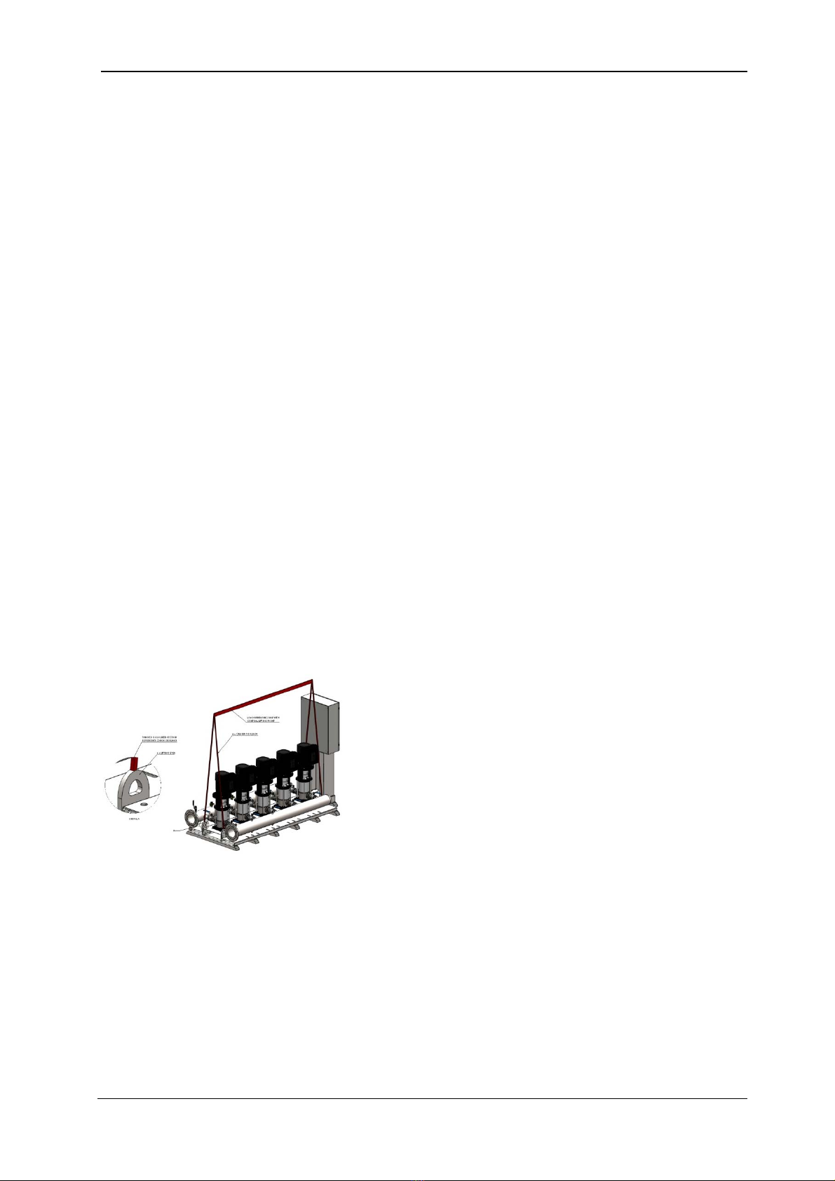
0.2.3 Do not lift the pumpset by pipework. Lift the pumpset by the container pallet using a
pallet/forklift or crane by passing strops underneath the skid using a spreader bar. Use built-in
lifting eyes on pump base where fitted, together with a spreader bar. Failure to utilise these
facilities will result in damage to the pumpset.
0.2.4 Store in a dry place to avoid damp conditions deteriorating the equipment.
0.2.5 Protect against dirt, damage and frost. It is absolutely essential that no foreign matter such as
pipe thread swarf, welding slag, grit or stones are allowed to enter the set. Debris of this type can
cause severe damage to the mechanical seals, diaphragms and impeller. Frost/freezing will
damage pumps/pipework and control panel components.
0.2.6 The equipment is only suitable for installation in a clean, dust free indoor environment, with
adequate protection from heat and frost, and sufficient ventilation to ensure cooling of the
motors. Ambient air temperature should be between 5 and 40 degrees centigrade, non-
condensating. Operation outside of these conditions could seriously damage the equipment. If
condensation in the motors is likely to occur, open the drain holes in the motor flange (where
fitted).
0.2.7 If the equipment were to be stored or taken out of service for a period of time (e.g. 1 week or
more), then we would recommend draining the equipment of all water/liquid (with due regard to
any local regulations) to prevent frost damage to components. When restarting is required we
would recommend commissioning by our authorised service agent.
0.2.8 Ensure the base/foundation/plinth/wall to which the equipment is to be attached has sufficient
mass compared to the equipment, in order to avoid noise/vibration transmission. E.g. the mass of
the base should be at least five times the mass of the equipment.
0.2.9 Ensure the electrical supply is the correct voltage, current, frequency and type for the
equipment supplied and that suitable circuit protection equipment is installed in the supply.
Incorrect electrical installation could be an electric shock/burns/fire hazard.
0.2.10 When accessing the control panel to make electrical connections adopt anti-static procedures
e.g. wear anti-static earthed wristband, to avoid risk of damaging the controller.
0.2.11 All products that are packaged to include Pressure vessel(s)/Hydraulic
Accumulator(s)/Expansion Vessel(s) are classed as “Assemblies” under the Pressure Equipment

Aquamatic Series
Page 7of 32
AquaTech-Pressmain Instruction Manual\Aquamatic Series AMV, AMF, HYAV
Directive (PED). Where units are despatched with “Loose” vessel(s) for assembly on site it is
absolutely essential that they be installed as detailed in the instructions using the fittings
provided where appropriate. Failure to observe this will nullify compliance with the PED and
may present a safety hazard. Your warranty may also be affected.
0.2.12 Where Hydraulic Accumulator(s)/Expansion Vessel(s) are supplied as a loose item, they must be
installed/connected correctly before operating the equipment, otherwise serious damage from
over-pressure/pump overheating could occur.
0.2.13 Do not operate this equipment/pumpset prior to commissioning (section 2.2) This could cause
irreparable damage to equipment/pumpset/pipework/system components.
0.2.14 Isolate the equipment/pumpset before pressure testing system. Excess pressure could
irreparably damage the pressure transducer, pressure switches (where fitted) and the
diaphragms of pressure vessel/hydraulic accumulators.
0.2.15 It is the installers’ responsibility to ensure subsequent pipework etc can accept the pressures
generated by the equipment/pumpset and to install an overpressure safety device into the
system with due respect to the suction pressure present on the pumpset, the pump closed valve
pressure stated on the pump, the maximum working pressure stated on any of the attached
pressure vessels and any other device connected to the system e.g. boilers, calorifiers etc.
0.2.16 When chlorination of the system is carried out, ensure that any residual chlorine is removed by
thorough flushing as detailed in the HSE approved code of practice L8, to avoid damaging the
equipment/pumpset. The normal level of chlorination is up to 2 parts per million (ppm), but
shock dosing for sterilization purposes, at 25-50 ppm for 24-48 hours is acceptable as long as all
chlorine is removed once the process is complete. Chlorination beyond these limits could
seriously damage pumpset components and WILL NOT be covered by the warranty.
0.2.17 The installer/user is responsible for the installation of the correct earthing and protection
according to valid national and local standards. All operations must be carried out by a suitably
qualified person.
0.2.18 The equipment is only suitable for earth referenced supplies and must be permanently earthed
to avoid electric shock hazard.
0.2.19 The equipment must be permanently earthed with appropriate sized Earthing.
0.2.20 Equipment containing variable speed drives/motors has high earth leakage current >3.5mA and
will require additional earth bonding whereby a single conductor of increased size or duplicate
earth conductors must be provided.
0.2.21 Never perform high voltage resistance tests on control panels, variable speed drives/motors
without first disconnecting the panel/drive/motor from the circuit being tested as this will
damage the built in electronic components.
0.2.22 Equipment containing variable speed drives/motors that has been stored/not powered up for
long periods of time (i.e. 1 year or more) may require the variable speed drive/motor capacitors
to be reformed. Please contact AquaTech-Pressmain for more information. Failure to reform
capacitors will result in drive/motor damage.
0.2.23 Metal parts (e.g. heat sinks) may reach temperatures of 90 degrees centigrade.
0.2.24 RCD’s/ELCB’s are not recommended for use with variable speed drives/motors. Where their use
is mandatory use type B RCD’s. For single phase sets with inverter motors the earth leakage
circuit breaker must trip out when earth fault currents with DC content (pulsating DC) occur.
For three phase sets with inverter motors the earth leakage circuit breaker must trip out when
earth fault currents with DC content (pulsating DC) and smooth DC earth fault currents occur.
0.2.25 RCD’s/ELCB’s suitable for use with variable speed drives/motors are not suitable for personnel
protection.
0.2.26 EMC – inverter motors 0.37kW to 7.5kW Electromagnetic disturbance – first environment
(residential areas) – unrestricted distribution, corresponding to CISPR 11, class B, group 1.
Inverter motors= > 11kW Electromagnetic disturbance – first environment (residential areas) –
restricted distribution. Immunity to Electromagnetic disturbance – second environment
(industrial areas) – unrestricted distribution, corresponding to CISPR 11, class A, group 2.
Inverter motors => 11kW for installation in first environment (residential areas) require
additional EMC filter to obtain class B, group 1 status.

Aquamatic Series
Page 8of 32
AquaTech-Pressmain Instruction Manual\Aquamatic Series AMV, AMF, HYAV
0.2.27 EMC - With respect to BS EN61000-3-2 this equipment is defined as ‘professional equipment’
and therefore the installer/user may need to seek permission from the supply utility to connect
this equipment to the public low voltage mains supply.
0.2.28 Where “Expansion vessels” are used on Domestic hot water systems (DHWS) or LTHW heating
system pressurisation units, the temperature of the fluid returning to the vessels should not
exceed 70 degrees Centigrade as this could damage the vessel diaphragm. Where the
temperature exceeds 70C an intermediate cooling vessel should be fitted.
0.2.29 Where “Expansion vessels” are used on Domestic hot water systems (DHWS) or LTHW heating
system pressurisation units, the glycol content in the water must not exceed 50%.
0.2.30 Drain cocks/valves and air bleed screws must not be left open as this could cause flooding.
0.2.31 Combined Booster set and Domestic Sprinkler unit (AMV-FE “Booster+Sprinkler” units).Where
the pumpset is used to supply the domestic cold water services and combined with a connection
to the domestic sprinkler system (BS9251) the pumpset generally works as described in this
manual for the AMV-FE and/or HY-AV units, with the following exceptions/additions: -In the
event of a fire there must be a volt-free signal from the sprinkler system to force the booster set
into “fire sprinkler mode” and run all pumps at 100% speed until manually switched off at the
mains isolator switch (IS1). This is in accordance with BS9251 code of practice “The sprinkler
system is normally only to be turned off following liaison with the fire and rescue service and
when deemed safe to do so”. Note: pumps must be in “Auto” if they have been switched to hand
or off they will perform their normal hand or off function. If pumps are left running in “fire
sprinkler mode” with no or low flow, then the pumps will quickly (within minutes) heat up leading
to pump seal failure and leakage, possibly followed by seizure. Damage of this type will not be
covered under warranty.
0.3 CAUTIONS FOR OPERATION/USER
0.3.1 READ GENERAL SAFETY INFORMATION 0.0, WARNINGS 0.1 and CAUTIONS 0.2, 0.3 & 0.4
0.3.2 The unit should only be operated/used by a competent person; A competent person is someone
who is technically competent and familiar with safety practices and the hazards involved.
0.3.3 The Owner/User of this equipment has a Legal Responsibility to ensure that it is subject to
regular formal inspections. See Section 3. Servicing, for details.
0.3.4 Where Hydraulic Accumulator(s)/Expansion Vessel(s) are supplied as a loose item, they must be
installed/connected correctly before operating the equipment, otherwise serious damage from
over-pressure could occur.
0.3.5 The set must not be run until commissioned by an authorised AquaTech-Pressmain agent, this
could irreparably damage the pump set and/or system components/pipework connected to it.
0.3.6 The pumpset should be left switched ON with the pumps switched to AUTO (where appropriate)
for normal operation.
0.3.7 Where appropriate the pumpset should not be left in “Hand” operation for more than 1 minute.
This could lead to severe damage of pumpset components and/or pipework system from over-
pressure and/or overheating.
0.3.8 Ensure pumpset has an adequate water supply at all times to prevent dry running causing pump
seal damage and water leakage.
0.3.9 Do no attempt to start pumps without liquid in volutes (pumps must be fully primed); mechanical
seals must have a film of liquid between faces for proper operation and to prevent damage.
0.3.10 Minimum flow rate: Due to the risk of overheating, do not use the pump at a flow below the
minimum flow rate. For cold water this is generally 10% of the pump flow rate as displayed on
the pump data plate, on the pump body.
0.3.11 Portable telephones or other electro-magnetic equipment must not be used near the set to
avoid corruption of program and unpredictable operation of unit.
0.3.12 Combined Booster set and Domestic Sprinkler unit (AMV-FE- “Booster+Sprinkler”
units).Where the pumpset is used to supply the domestic cold water services and combined with
a connection to the domestic sprinkler system (BS9251) the pumpset generally works as
described in this manual for the AMV-FE and/or HY-AV units, with the following

Aquamatic Series
Page 9of 32
AquaTech-Pressmain Instruction Manual\Aquamatic Series AMV, AMF, HYAV
exceptions/additions: -In the event of a fire there must be a volt-free signal from the sprinkler
system to force the booster set into “fire sprinkler mode” and run all pumps at 100% speed until
manually switched off at the mains isolator switch (IS1). This is in accordance with BS9251 code
of practice “The sprinkler system is normally only to be turned off following liaison with the fire
and rescue service and when deemed safe to do so”. Note: pumps must be in “Auto” if they have
been switched to hand or off they will perform their normal hand or off function. If pumps are
left running in “fire sprinkler mode” with no or low flow, then the pumps will quickly (within
minutes) heat up leading to pump seal failure and leakage, possibly followed by seizure. Damage
of this type will not be covered under warranty.
0.4 CAUTIONS FOR MAINTENANCE
0.4.1 READ GENERAL SAFETY INFORMATION 0.0, WARNINGS 0.1 and CAUTIONS 0.2, 0.3 & 0.4
0.4.2 The unit should only be operated/maintained by a competent person; A competent person is
someone who is technically competent and familiar with safety practices and the hazards involved.
0.4.3 Where the set is fitted with Building Management Services (BMS) interconnections, notify the
appropriate persons before switching OFF for maintenance or adjustments, to avoid
unnecessary alarm conditions occurring. WARNING: With pumpset isolator OFF, mains voltage
may still be present from BMS system. This constitutes an Electric shock hazard.
0.4.4 To prevent seizing, pumpsets must not be left unused for long periods (e.g. 1 week).
0.4.5 The pumps must be run regularly to avoid stagnation of water in the pumps/pipework (e.g. daily).
0.4.6 Do not vent air from air valves on vessels. These are for adjustment of pre-set cushion pressures.
If wrongly adjusted this will lead to incorrect operation of the pumpset and possible damage to
pumps, pipework and system components from overheating and over-pressure.
0.4.7 Switch OFF pumpset before accessing pumps and/or control panel.
0.4.8 Combined Booster set and Domestic Sprinkler unit (AMV-FE- “Booster+Sprinkler”
units).Where the pumpset is used to supply the domestic cold water services and combined with
a connection to the domestic sprinkler system (BS9251) the pumpset generally works as
described in this manual for the AMV-FE and/or HY-AV units, with the following
exceptions/additions: -In the event of a fire there must be a volt-free signal from the sprinkler
system to force the booster set into “fire sprinkler mode” and run all pumps at 100% speed until
manually switched off at the mains isolator switch (IS1). This is in accordance with BS9251 code
of practice “The sprinkler system is normally only to be turned off following liaison with the fire
and rescue service and when deemed safe to do so”. Note: pumps must be in “Auto” if they have
been switched to hand or off they will perform their normal hand or off function. If pumps are
left running in “fire sprinkler mode” with no or low flow, then the pumps will quickly (within
minutes) heat up leading to pump seal failure and leakage, possibly followed by seizure. Damage
of this type will not be covered under warranty.

Aquamatic Series
Page 10 of 32
AquaTech-Pressmain Instruction Manual\Aquamatic Series AMV, AMF, HYAV
1. INSTALLATION INSTRUCTIONS
These instructions are intended for the installer of this pressure booster set. Please follow them
carefully.
The unit should only be installed by a competent person; A competent person is someone who is
technically competent and familiar with safety practices and the hazards involved.
Failure to install the equipment as recommended below could invalidate the warranty provided
by AquaTech-Pressmain to the purchaser.
1.1 ADDITIONAL WARNINGS
DO NOT TOUCH ANY LIVE PARTS FOR AT LEAST 5 MINUTES AFTER
SWITCHING OFF THE POWER. Failure to observe this will constitute an
ELECTRIC SHOCK HAZARD.
READ GENERAL SAFETY INFORMATION 0.0, WARNINGS 0.1 and CAUTIONS 0.2, 0.3 & 0.4
1.2 ADDITIONAL CAUTIONS
1.2.1 READ GENERAL SAFETY INFORMATION 0.0, WARNINGS 0.1 and CAUTIONS 0.2, 0.3 & 0.4.
1.2.2 AMV-FB units must have the low water protection float switch fitted into the supply tank in
order to protect the pumps from running dry and damaging the pump seals. AMV-FE sets have
the Low Water protection sensor built into the suction manifold.
1.2.3 For low water protection float switch fitted into the side of the supply tank, take care when
drilling 23mm diameter hole in tank, this should only be carried out by a competent person.
Normal supply is an externally fitted switch with compression seal. Use the green (Viton) seal.
1.3 PROCEDURE
1.3.1 OFF-LOADING AT SITE
Do not lift pumpset by pipework. Lift the pumpset by the container pallet using a pallet/forklift
or crane by passing strops underneath the skid using spreader bar.
Use built-in lifting eyes on pump base where fitted, together with a spreader bar (see below).
Failure to utilise these facilities could result in damage.
Fig. 1.1 Typical lifting eye arrangement on larger booster set bases.
1.3.2 LOCATION
If the set is to be installed in an unheated room, ensure that there is adequate frost protection.
The location of the equipment should have adequate drainage, bunding or other appropriate
measures to protect assets and the building fabric in the event of leakage or water spillage.
Failure to provide such measures may result in water damage to property and assets.
Ensure that location for pumpset provides adequate clear space to accommodate unit with
reasonable access to all parts; AquaTech-Pressmain recommend a minimum distance of 500mm
all round. There must be sufficient room to: -
fully open consumer unit/control panel door;
lift and withdraw pumps;

Aquamatic Series
Page 11 of 32
AquaTech-Pressmain Instruction Manual\Aquamatic Series AMV, AMF, HYAV
withdraw diaphragms from vessels.
remove manifolds from pumps.
If necessary, provide overhead lifting eyes for possible future use.
Any Hydraulic Accumulator supplied should be located as near as possible to the discharge side
of the pumpset.
Should any of these location conditions not be satisfied AquaTech-Pressmain reserve the right
to charge labour on any warranty work required on the pumpset.
1.3.3 FIXING
Install the set on a flat, even and level surface, where practical on a raised plinth to keep set
above damp floor.
Locate unit in position; fit anti-vibration mounts if supplied. If necessary, level the base by
inserting packing strips adjacent to bolt positions. Firmly attach pumpset to base.
1.3.4 PIPEWORK
Fig. 1.2 Typical Pipework arrangement
1.3.4.1 Arrange mains water breaktank to ensure fully flooded suction conditions to all pumps within
the unit, unless otherwise specified. Minimum requirement = 0.15 bar (1.5 metres)
1.3.4.2 Arrange the suction pipework to be self-venting between the mains water breaktank and the
pumpset suction manifold (see fig.1.2).
1.3.4.3 Fit isolating valves to the suction side and discharge side of the pumpset (see fig.1.2), to enable
the pumpset to be isolated from the system for maintenance purposes.
1.3.4.4 Under no circumstances fit an extra non-return valve, to either the suction or the discharge, as
it may interfere with the correct operation of the non-return valves already fitted as standard in
the pumpset.
1.3.4.5 Remove any protective end plugs from suction and discharge pipework on pumpset.
1.3.4.6 Connect site pipework to suction and discharge manifolds, ensuring adequate support is
provided to avoid imposing pipe strain on manifolds. The connecting pipework should not be
smaller than that of the pumpset. Where flexible pipe connections are fitted, ensure that the
correct distance is allowed between flanges, that the pipework is also aligned axially, and no
strain is imposed by the site pipework. (see fig.1.3)
Discharge
Isolating
Isolating
valve
valve
Consumer
Unit/Control
Panel
Suction
Pumpset
Outlet pipe to be
self venting
Air must disperse
before entry to
pumpset supply pipe
Low level float switch
(AMV-FB, DM-VS)
Top or side mounted
Flow Through
Vessel
OPTIONAL EXTRA
Flow Through Vessel(s)
2.1/2 times
diameter

Aquamatic Series
Page 12 of 32
AquaTech-Pressmain Instruction Manual\Aquamatic Series AMV, AMF, HYAV
Fig. 1.3 Flexible pipework connections
1.3.4.7 Where Hydraulic Accumulator(s)/Expansion Vessel(s) are supplied as a loose item, they must be
installed/connected correctly before operating the equipment, otherwise serious damage from
over-pressure/pump overheating could occur (see also 1.3.5 for correct mounting).
1.3.4.8 All hydraulic accumulators and expansion vessels fitted to the system must have isolating and
drain off valves to enable them to be serviced and removable pipework to enable the diaphragm
to be replaced.
Fig. 1.4a & b Isolation valve on manifold & Flexible hose with drain cock on vessel (non-flow through
vessel shown)
1.3.4.9 AMV-FE, AMF and HY-AV sets have a low water protection sensor mounted in the suction
pipework, no further action is required.
1.3.4.10 AMV-FB sets; Install low level float switch in mains water breaktank at a level which stops the
pumps when the water level reaches a point 2½ times the outlet pipe diameter above the outlet
pipe. Make contacts = low water fault. Break contacts = water level ok.
1.3.4.11 Ensure that any swarf, debris, etc that may have entered the tank is removed as it could cause
damage to the tank or connected equipment.
1.3.4.12 For side mounted level switch (where supplied), drill a 23mm diameter hole in the side of the
tank at the correct height, assemble switch in correct order (as shown below), insert into tank
from the outside ensuring the float is the right way up, right up to the flange of the seal, tighten
nut to deform seal, sealing the hole in the tank. Connect the wires to the appropriate terminals of
the pumpset.
Level Switch mounted 2½ pipe diameters above ou tlet
Low Level Alar m
(make contacts)
Level OK
(break contacts)
Drill 23mm diameter hole through
wall to fit level switch
seal
washer nut
Fig. 1.5 Typical Low Water float switch for AMV-FB
Shear Angulation
BORE
(mm)
NOM.
Length
(mm) (mm) (mm) (mm)
AXIAL
EXTN
AXIAL
COMP
SHEAR
MAX PERMISSIBLE MOVEMENT
32
40
50
65
80
100
125
150
4
4
5
6
6
10
10
10
8
8
8
12
12
18
18
18
8
8
8
10
10
12
12
12
15
15
15
15
15
15
15
15
130
130
130
130
130
130
130
130
ANGULAR
MOVEMENT
DEG
Compression Extension
OD

Aquamatic Series
Page 13 of 32
AquaTech-Pressmain Instruction Manual\Aquamatic Series AMV, AMF, HYAV
1.3.5 FLOW THROUGH VESSELS
AMV, AMF and some HY-AV sets have 12, 18 or 25 litre flow through vessel(s) supplied loose for site
fitting into the discharge manifold via a flowjet isolation and drain valve. The number and size of vessels
supplied depends upon the number and size of pumps fitted.
Ensure “O-ring” is in place inside valve to prevent leakage.
Fig. 1.6a & b Fit flow through vessel into discharge manifold flowjet valve.
In order to reduce power consumption still further, we would recommend fitting an additional (optional
extra), larger flow through vessel to the discharge pipework of the system. This would store an amount of
water at high pressure which would then be released to satisfy small demands from the system thereby
reducing the number of pump starts.
Larger floor standing flow through vessels may be provided as optional extra items fitted on site. Sizes
available from 60 litre to 3,000 litre with 1 ¼” up to DN100 connection.
Fig. 1.7 Typical Flow Through Vessels (12l, 300l and 800l shown).
All vessels must be securely mounted to prevent any movement from imposing strain on the attached
pipework. Vessels MUST be mounted vertically on the integral legs with water connection lowermost.
Set up the vessel so the air charge filling valve (top) and the diaphragm (bottom) are accessible for future
maintenance. All vessels must have isolating and drain off valves fitted to enable them to be serviced. The
connecting pipework should be removable to give access for replacing the diaphragm and should be the
same size as the vessel connection to minimise friction losses. In the case of floor standing vessels, if the
system cannot be turned off then supply dual flow through vessels connected in parallel to enable
isolation/draining of one vessel at a time. Contact AquaTech Pressmain for further information.
Set the air cushion pre-charge pressure to the correct level (see section 2.4), dependent on the application
required for the vessel. Refer to the Operating parameters at the back of this manual or contact Aquatech-
Pressmain for advice.
Caution: If the air cushion pre-charge pressure required exceeds 4.0 Bar then you must follow the
procedure shown in section 2.4 to avoid damaging/rupture of the internal diaphragm and consequences
of. E.g. High and/or low pressure problems, unstable pump operation.

Aquamatic Series
Page 14 of 32
AquaTech-Pressmain Instruction Manual\Aquamatic Series AMV, AMF, HYAV
1.3.6 ELECTRICAL
WARNING: DO NOT TOUCH ANY LIVE PARTS FOR AT LEAST 5 MINUTES AFTER
SWITCHING OFF THE POWER TO ALLOW CAPACITORS TO DISCHARGE
READ GENERAL SAFETY INFORMATION 0.0, WARNINGS 0.1 and CAUTIONS 0.2, 0.3 & 0.4
1.3.6.1 All wiring must comply with the latest edition of local wiring Regulations.
1.3.6.2 Wear anti-static wrist strap at all times to avoid static discharge causing problems with the built
in electronic program.
1.3.6.3 Connect incoming electrical mains supply to identified terminals on isolator SW1 in consumer
unit or IS1 in control panel (see fig. 1.8a or b). Ensure voltages and frequency indicated on the
motor nameplates and wiring diagrams correspond with supply mains data and that the supply
fuse type & rating is correct for the total current rating of the equipment. Note: some 3 phase
units may require Neutral supply for special applications. Refer to wiring diagram supplied with
the unit or AquaTech-Pressmain.
1.3.6.4 AMV-FB sets; complete the wiring from the master pump (the one with the pressure sensor)
terminals 2 & 10 (remove wire link between 2 & 10) to the installed low level float switch in
mains water breaktank. Make contacts = low water fault. Break contacts = water level ok.
1.3.6.5 Where optional remote fault signal is required connect volt free terminals in motor terminal box
for AMV-FB units or in control panel for AMV-FE, AMF & HY-AV units, to remote panel. See fig
1.8a or b and wiring diagram provided.
1.3.6.6 Complete any required earth bonding.
Fig. 1.8a Typical example of AMV-FB 400VAC 3 phase electrical connections

Aquamatic Series
Page 15 of 32
AquaTech-Pressmain Instruction Manual\Aquamatic Series AMV, AMF, HYAV
Fig. 1.8b Typical example of AMV-FE, AMF & HY-AV electrical & BMS connections
1.3.7 GUIDANCE ON SELECTING THE CORRECT EARTH LEAKAGE PROTECTION DEVICE FOR
BOOSTER SETS
All wiring must comply with the latest edition of local wiring Regulations.
Where the incoming electrical supply to the booster set is to be protected by the customer using an Earth
Leakage Protection Device, we would recommend that in order to prevent nuisance tripping, follow the
information provided below: -
1. Generally, a booster set with pumps/motors that are single phase “variable speed” should have
protection that is of the RCBO style, with a type “C” MCB part (inrush 5-10 x Amp rating) and
30mA class “A” RCD part (residual AC/pulsed DC fault currents) for twin pump sets, or
100/300mA class “A” RCD part (residual AC/pulsed DC fault currents) for triple pump sets.
2. Generally, a booster set with pumps/motors that are three phase “variable speed” should have
protection that is of the RCCB style, with a 30mA or 100/300mA (dependent upon motor size and
therefore total leakage current) class “B” RCD part (residual AC/pulsed DC & smooth DC fault
currents) which is not of the delayed tripping type.
Variable speed
Motor Size (kW) Leakage Current
(mA)
0.75 > 3.0 3.5
4.0 > 5.5 5.0
7.5 10.0
11.0 > > 10.0
Table 1, Leakage currents according to EN61800-5-1
If you require any further assistance, please contact AquaTech-Pressmain.
DE F GH J KL M NOP R ST U VW X YZABC
4
5
6
7
8
1
2
3
9
10
11
12
13
c
no
BMS volt free outputs
max 240VAC 50Hz 1.5A
Display
Pump 1 Auto/Off/Hand
Pump 2 Auto/Off/Hand
2020PLUS CONTROLLER
O
A1
A2
A3
A5
A7
A6
A4
A9
A8
nc High
Pressure
Low
Pressure
High/Low
Water
Common
Warning
System
Healthy
Fire Sprinkler
Mode Activated
Pump
Failed
Transducer
Failed
PCB2
24VAC
12VAC
0V
111
110
KEYPAD PCB3
PCB1
INTERFACE
CARD
EPB-120134
TB1
OPTIONAL
Remote emergency stop
(when fitted). 24VAC.
Make to run, break to stop.
IS1
L2
T2
OFF
L1
T1
PE
L3
T3
ON
SUPPLY
415V 3Ph.&E 50Hz.
or 240V 1Ph.&E
N
IP1
4-Channel
Analogue
Input
Module
IP2
4-Channel
Level
Sensing
Module
IP3
4-Channel
Digital
Input
Module
(Non-Inv)
IP4
4-Channel
Digital
Input
Module
(Non-Inv)
IP5
8-Channel
Analogue
Output
Module
c
no
nc
c
no
nc
c
no
nc
c
no
nc
c
no
nc
c
no
nc
c
no
nc
201
200
TB1

Aquamatic Series
Page 16 of 32
AquaTech-Pressmain Instruction Manual\Aquamatic Series AMV, AMF, HYAV
2. USER INSTRUCTIONS
2.1 CUSTOMER ASSURANCE
AQUATECH-PRESSMAIN ASSURE YOU THAT IF ANY PART OF THIS EQUIPMENT BECOMES
DEFECTIVE DUE TO FAULTY MANUFACTURE OR MATERIALS WITHIN 24 MONTHS FROM THE
DATE OF INVOICE OR 12 MONTHS FROM DATE OF COMMISSIONING BY AUTHORISED
AQUATECH-PRESSMAIN AGENT, THE PART WILL BE REPAIRED OR REPLACED.
The only conditions are: -
The equipment must have been installed, commissioned, operated and maintained as recommended
by AquaTech-Pressmain.
The equipment must not have been neglected, misused, modified, or used for any other purpose than
its original application.
The commissioning should be carried out within 6 months of the date of invoice by an authorised
AquaTech-Pressmain agent.
This Assurance does not apply to those items not supplied by us or to defects arising from parts not
made or approved by AquaTech-Pressmain. The individual manufacturers own policies for dealing
with defects will apply.
Any part repaired or replaced under these Assurances will be covered for the balance of the
appropriate Assurance period.
If we have any disagreement about these Assurances which we are unable to resolve we will both
abide by the decision of an agreed Arbitrator or, if we are unable to agree, one appointed by the
Building and Engineering Services Association (B & ES) Arbitration Scheme Rules.
These Assurances are in addition to, and do not detract from, the contractual rights you have under
Statute or at common law.
Failure to comply with the installation, commissioning and maintenance procedures will invalidate the
warranty.
For full details please see the AquaTech-Pressmain "CONDITIONS OF SALE"
2.2 COMMISSIONING
Whilst this set has been tested in the factory to the required settings (detailed in operating parameters at
the back of instruction manual), it is impossible to simulate the actual on-site conditions, especially if they
are unusual. Also, the settings may have been disturbed since leaving the factory.
Therefore, we strongly recommend the set is commissioned by our authorised agent who will prepare the
set, make any necessary adjustments and leave the set in operational order.
Commissioning is a requirement to validate the Warranty (see Customer Assurance)
Prior to requesting an engineer to attend the site for commissioning, the client must ensure that;
the equipment has been correctly installed;
a written scheme of examination has been obtained where required under the Pressure Systems
Safety Regulations;
any necessary chlorination or other treatment has been completed;
an adequate water supply and permanent electricity supply are available;
the pipework etc in the building being served by the pumpset is capable of accepting the
generated pressures.

Aquamatic Series
Page 17 of 32
AquaTech-Pressmain Instruction Manual\Aquamatic Series AMV, AMF, HYAV
2.3 OPERATING INSTRUCTIONS
These pumpsets are used for increasing the supply pressure of cold potable water and other liquids.
In addition AMV-FE and HYAV-DS units built in accordance with BS9251 are capable of supplying
Domestic Sprinkler installations (when “Fire Sprinkler Mode” is activated) as well as domestic water
services.
2.3.1 ADDITIONAL WARNINGS
DO NOT TOUCH ANY LIVE PARTS FOR AT LEAST 5 MINUTES AFTER
SWITCHING OFF THE POWER
READ GENERAL SAFETY INFORMATION 0.0, WARNINGS 0.1 and CAUTIONS 0.2, 0.3 & 0.4.
2.3.2 ADDITIONAL CAUTIONS
2.3.2.1 READ GENERAL SAFETY INFORMATION 0.0, WARNINGS 0.1 and CAUTIONS 0.2, 0.3 & 0.4.
2.3.2.2 AMV-FB units must have the low water protection float switch fitted into the supply tank in
order to protect the pumps from running dry and damaging the pump seals. AMV-FE, AMF & HY-
AV sets have the Low Water protection sensor built into the suction manifold.
2.3.2.3 Combined Booster set and Domestic Sprinkler unit (AMV-FE “Booster+Sprinkler” units).Where
the pumpset is used to supply the domestic cold water services and combined with a connection
to the domestic sprinkler system (BS9251): -In the event of a fire there must be a volt-free signal
from the sprinkler system to force the booster set into “fire sprinkler mode” and run all pumps at
100% speed until manually switched off at the mains isolator switch (IS1). This is in accordance
with BS9251 code of practice “The sprinkler system is normally only to be turned off following
liaison with the fire and rescue service and when deemed safe to do so”. Note: pumps must be in
“Auto” if they have been switched to hand or off they will perform their normal hand or off
function. If pumps are left running in “fire sprinkler mode” with no or low flow, then the pumps
will quickly (within minutes) heat up leading to pump seal failure and leakage, possibly followed
by seizure. Damage of this type will not be covered under warranty.
2.3.3 NORMAL OPERATION - COLD WATER PRESSURE BOOSTER
The pressure booster set increases and maintains the supply pressure to a preset 'Duty' pressure.
The pumpset consists of two or more pumps mounted on a baseframe together with associated suction
and discharge pipework and valves. For AMV-FB units, the controls are motor mounted. For AMV-FE,
AMF and HYAV units, the 2020Plus controller is mounted in the control panel. In all cases they work in
conjunction with a hydraulic accumulator.
In addition AMV-FE and HYAV-DS units built in accordance with BS9251 are capable of supplying
Domestic Sprinkler installations (when “Fire Sprinkler Mode” is activated) as well as domestic water
services. See section 2.3.4 as well as the information below.
2.3.3.1 The AMV-FE, AMF and HYAV units control is by AquaTech-Pressmain “2020Plus”
Microprocessor, with a 2-line by 20 or 24-character display on the control panel, showing the
current system pressure and status.
When switched on the display shows,
then self-checks, flashing all LED lights on keypad,
and identifies configuration for pump operation
(e.g. “Hydro-pneumatic” pressure booster set)
followed by the system status and pressure
AQUATECH 2020Plus V4.00
PRESSMAIN
Hydro-Pneumatic
PRESSURE SYSTEM IS O.K.
Pressure ………… bar

Aquamatic Series
Page 18 of 32
AquaTech-Pressmain Instruction Manual\Aquamatic Series AMV, AMF, HYAV
2.3.3.2 For “normal” operation, all pump suction and discharge valves should be left open, all hydraulic
accumulator/expansion vessel isolating valves should be left open, and drain cock/valves should be left
closed. Should it be necessary to have a situation that is not “normal” operation, then we would strongly
recommend attendance to site by our trained/authorised service personnel. Please contact AquaTech-
Pressmain for more details.
2.3.3.3 Pump Motor Eye (all variable speed models)
The operating condition of the motor is indicated by the
Eye on the motor control panel. See below
Fig. 2.1 Pump motor eye
Motor eye

Aquamatic Series
Page 19 of 32
AquaTech-Pressmain Instruction Manual\Aquamatic Series AMV, AMF, HYAV
2.3.3.4 Pump Operation
Intermittent running duty pump with or without one or more optional support pumps meeting demand.
Pumps are run at Variable speed, except AMF models which are fixed speed.
When demand on the system occurs (e.g. when a tap is turned on or a hose reel valve is opened) the
pressure falls as water from the hydraulic accumulator is discharged into the system. The pump operates
at the set duty pressure and will run for a set period or until the demand is satisfied and the accumulator is
replenished. Should the pressure continue to fall due to increased demand etc. the support pump(s) will
automatically start in sequence and run for a set minimum time or until the demand is satisfied.
2.3.3.5 Duty Pump Rotation.
To spread the wear evenly across all the pumps, their sequence is automatically rotated.
AMV-FE, AMF and HYAV Models only:
2.3.3.6
Pumpsets with more than 4 pumps use the
<Enter> key (9) to toggle operation of the keypad and
LED lights between pumps 1 to 4 and pumps 5 to 8.
2.3.3.7 Automatic Restart (when “manual restart” is set to “not enabled” on 2020 Plus controller)
If there is an interruption to the electrical supply the unit will automatically restart on restoration of the
supply. Pumps will restart at timed intervals and at reduced speed dependent upon model type.
2.3.3.8 Manual Restart (when set to “enabled” on 2020 Plus controller)
If there is an interruption to the electrical supply, or there is a low water level condition, the unit will need
to be manually reset on restoration of the supply, or low water level condition, by pressing the “Reset
Alarm” key. Pumps will then restart at timed intervals and at reduced speed dependent upon model type.
All Models: -
2.3.3.9 Pressure Setting
The pumpset is set at the required 'duty' pressure at the factory. If necessary, the pressure will be adjusted
at commissioning to suit local conditions.
2.3.3.10 “REPRESS/REFILL” feature
(for variable speed booster sets only)
When programmed to suit the site conditions, this parameter is designed to help fill the booster sets
system riser/pipe work gradually, after a power interruption.
e.g. we have found in some instances during a power cut that occupiers of flats in a tower block, would use
water until the main water riser was partially or completely empty, resulting in the system pressure
possibly dropping to 0.0Bar. When power is restored, the booster set would allow all of the pumps to
switch on in sequence and operate at full speed (100%) to try to build the pressure back up to the normal
level. This could result in fittings at the top of the riser being subjected to high velocity water coming to a
sudden stop, and the resultant kinetic energy loosening certain types of fittings. In order to help prevent
this situation the controller has some added features to refill the system gradually under automatic
control. Once set at commissioning no further user intervention is required.
2.3.3.11 Dry Running Protection
For AMV-FB units, the pumpset is supplied with a float switch for mounting in the mains water break tank,
which is wired back to the pump motor terminal box connections to stop the pumps in the event of a low
water condition in the break tank. (see Figs1.4 & 1.7 or wiring diagram provided).
The unit is supplied with a link that bridges the low water level switch connections, to inhibit operation
until the level switch is fitted.
Note: The pumps will not run until a level switch is fitted. See the wiring diagram supplied with the unit
for information.
The Low water level switch circuit is;
“Made” for fault condition (no water in tank)
“Open” for water available (water available in tank)
Pumps 5 and over
Pressure bar

Aquamatic Series
Page 20 of 32
AquaTech-Pressmain Instruction Manual\Aquamatic Series AMV, AMF, HYAV
For AMV-FE, AMF and HYAV units, the pumpset is supplied with a low water sensor built into the suction
manifold and pre-wired to the control panel. No further action is required.
2.3.3.12 Stop Function
The water flow from the pumpset is tested periodically by momentarily reducing the speed, if flow is
present then the pump(s) speed back up and continue on until a low flow condition is sensed, whereupon
the speed is increased until the pressure reaches a pre-determined stop pressure, nominally the duty
pressure x 1.2 for AMV-FB units, or the duty pressure for AMV-FE, AMF and HYAV units.
2.3.3.13 Low Pressure cut out
For AMV-FB units, if the system pressure falls to, or below 0.5 Bar for a pre-set period of time, the pumps
will stop to protect themselves and the system.
For AMV-FE, AMF and HYAV units, if the system pressure falls to, or below the low pressure alarm
parameter setting for the adjustable low pressure delay time period, the pumps will stop to protect
themselves and the system.
See the table below for the possible causes and cures
Cause Cure
system pressure remained at or
below low pressure setting for
duration of low pressure delay
timer, and lock out protection is
invoked.
Pumps are air locked and need
venting? Or running off end of
curve due to demand beyond
design limit? Pump(s) switched Off
or Tripped?
Rectify fault, switch pumps off,
bleed pumps of air and switch back
on.
2.3.3.14 Combined Domestic Booster set and Sprinkler unit (AMV-FE “Booster+Sprinkler” units)
Where the pumpset is used to supply the domestic cold water services and combined with a connection to
the domestic sprinkler system (BS9251) the pumpset generally works as described in this manual for the
AMV-FE and/or HY-AV units, with the following exceptions/additions: -
In the event of a fire there must be a signal from the sprinkler system to tell the booster set to go into “fire
sprinkler mode” and run all pumps at 100% speed (ramping up one pump at a time) until switched off at the
mains isolator. Note: pumps must be in “Auto” if they have been switched to hand or off they will perform
their normal hand or off function.
When in sprinkler mode the display shows “fire sprinkler mode”, sounds an audible alarm, releases healthy
relay, and records a date/time/event stamp in the fault log.
2.3.3.15 To view the parameters (AMV-FE, AMF and HYAV units only)
Press <SET/VIEW> on the keypad. Then, press the same key 4more times.
Press the <UP> (7) key, to view the next parameter.
Page through the parameters by using the <UP> (7) and <DOWN> (8) keys to view:
Various parameters will be displayed dependent upon unit type. The main parameters that customers are
interested in are shown on the following page.
Date and Time (24 hour clock) not password protected to
allow on site adjustment.
Fault Log (last 30 faults) press <view> to see log
followed by <up> (7) or
<down> (8) to view log.
press <enter> to return
Manual Restart upon power failure not password protected to
or low water level condition allow user to enable/disable
Time
14/01/15…….22:40:15
Fault Log
Manual Restart
Not enabled
This manual suits for next models
5
Table of contents
Popular Water Pump manuals by other brands

Regulus
Regulus CSE MIX W6-SC 1F Installation and operation manual

Crane
Crane DEMING 4507 Series Installation, operation & maintenance manual

GORMAN-RUPP PUMPS
GORMAN-RUPP PUMPS PRIME-AIRE Series manual

General Pump
General Pump KV Series Repair manual

Bühler technologies
Bühler technologies P2.3C Brief instructions

Calpeda
Calpeda CT Series operating instructions

BVA Hydraulics
BVA Hydraulics PE30M3N01A instruction manual

Roberts Gorden
Roberts Gorden EP 100 Installation, operation & service manual

AC Infinity
AC Infinity AC-AUS21 user manual

Graco
Graco Husky 1050e repair parts

Oerlikon
Oerlikon TURBOVAC series operating instructions

Sulzer
Sulzer RCP 250 Installation and operating instructions