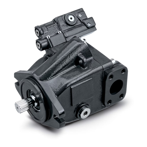
FILL-RITE nextec NX25-120 Series User manual

NX25-120 & NX25-240 SERIES AC FUEL TRANSFER PUMPS
Installation and Operation Manual

fillrite.com 2
| NX25-120 & NX25-240 SERIES AC FUEL TRANSFER PUMPS INSTALLATION AND OPERATION MANUAL
Table of Contents
Unique nextec Features .......................................................................................... 3
Safety Information.................................................................................................. 3
Fueling Safety......................................................................................................... 4
Installation ............................................................................................................. 4
Nozzle Boot Installation.......................................................................................... 4
Pump Foot Installation............................................................................................ 4
Anti‑Siphon Device ................................................................................................. 5
Tank Installation ..................................................................................................... 5
AC Power Connection............................................................................................. 6
Operational Safety.................................................................................................. 6
Operating Instructions............................................................................................ 7
Padlocking ............................................................................................................. 7
Dimensional Information ........................................................................................ 8
Technical Information ............................................................................................ 9
Servicing the Bypass Valve................................................................................... 10
Model Information..................................................................................................11
Accessory Packages ..............................................................................................11
Kits and Parts....................................................................................................... 12
Servicing Rotor, Vanes, and Shaft Seals............................................................... 12
Exploded View....................................................................................................... 13
Troubleshooting Guide ...........................................................................................14
Intelligent Tones ................................................................................................... 15
Limited Warranty Policy
Fill‑Rite Company warrants the goods manufactured shall be free from defects of materials and workmanship. Specific warranty details for individual
productscanbe found at fillrite.com.
Thank You!
Thank you for your loyalty to the Fill‑Rite®brand of fuel transfer pumps. Your safety
is important, so please read and thoroughly understand the procedures set forth
in this manual. In addition, please save these instructions for future reference and
record the model, serial number, and purchase date of your fuel transfer pump.
Protect yourself as well as those around you by observing all safety instructions
and adhering to all danger, warning, and caution symbols. Please register your
Fill‑Rite®product via info.fillrite.com/product_registration.
IMPORTANT RETURN POLICY
Please do not return this product to the store.For all warranty and product
questions, please contact Fill‑Rite Technical Support at 1 (800) 720‑5192 or via
MODEL#
SERIAL#
PURCHASE DATE:

fillrite.com 3
| NX25-120 & NX25-240 SERIES AC FUEL TRANSFER PUMPS INSTALLATION AND OPERATION MANUAL
Unique Features of the nextec Pump
Your nextec fuel transfer pump will perform differently from non‑intelligent pumps on start‑up and while operating. You will want to keep the following in mind as you begin to use and
learn how your nextec Intelligence pump operates.
• On initial start up, the pump may rev momentarily, but will slow down, as if idling, as it responds to the load it senses. This is a normal condition, and it will continue at this low
speed until you squeeze the handle on the dispensing nozzle to begin fluid flow.
• When you squeeze the nozzle handle to begin flow, the microprocessor in the pump will sense the change, and will raise the RPM’s to meet the load.
It is not uncommon for the pump to change RPM’s during operation. It will do this as it senses performance parameters are changing; for example, if you increase or decrease the
flow at the nozzle, the electronics controlling the motor will sense the changes and adjust the motor speed to optimize performance.
• If the pump senses a condition that is outside normal operating parameters (e.g. low input voltage), it will sound a series of tones to alert you to the condition, and to help you
diagnose it. See the “Intelligent Tones” section of the Troubleshooting Guide on page 14 for greater detail on this feature.
• Your nextec pump has a Continuous Duty Cycle, meaning it does not have to be shut off to “rest” after a specific period of use. This allows you to move from fueling one piece of
equipment to another without having to shut the pump off. The nextec Intelligence does, however, have an automatic shut off if the pump is left running in bypass mode (without
dispensing any fluid) for 20 minutes. This features protects from unnecessary power consumption and excessive wear to the pump in the event you forget to shut the pump off.
Should the pump turn itself off under these conditions, simply cycle the power switch off, then back on to restore pump operation.
• The nextec Intelligence will also shut the motor down if:
►Pump temperature exceeds threshold parameters
►Input voltage is outside threshold parameters
►Rotor is locked
Safety Information
3
Indicates a hazardous situation which, if not avoided, could result in death or serious injury.
Indicates information considered important but not directly hazard related.
Indicates a hazardous situation which, if not avoided, could result in moderate or minor injury.
WARNING
CAUTION
NOTICE
DANGER Indicates a hazardous situation which, if not avoided, will result in death or serious injury.
DANGER Electrical wiring should be performed with extreme caution and in compliance with local, state, and national electrical code NEC/ANSI/NFPA 70,
NFPA 30, and NFPA 30A, as appropriate for the intended use of the pump. Threaded rigid conduit, sealed fittings, and conductor seal should be
used where applicable. The pump must be properly grounded. It is recommended that a licensed electrician perform the installation. Improper
installation or use of this product will result in serious bodily injury or death!
DANGER To ensure safe and proper operation of your equipment, it is critical to read and adhere to all of the following safety warnings and precautions.
Failure to follow instructions below, improper installation, or use of this product, will cause serious bodily injury or death!
• NEVER smoke near the pump, or use the pump near open flames when pumping a flammable liquid! Fire may result!
• This product shall not be used to transfer fluids into any type of aircraft.
DANGER To minimize static electricity build up and possible explosion, use only static wire conductive hose when pumping flammable fluids, and keep
the fill nozzle in contact with the container being filled during the filling process. Spark / static discharge may cause explosions.
Threaded pipe joints and connections should be sealed with the appropriate sealant or sealant tape to minimize the possibility of leaks. Leaking
fuel may cause the potential for fire and explosion.
WARNING
The pump motor is equipped with electronic protection from thermal overload; if overheated, the motor will slow down. After the motor has cooled, you
may cycle power or the switch to reset this safety feature and continue use. The pump will not restart until properly cooled.
CAUTION
About This Manual
From initial concept and design through final production, your Fill‑Rite fuel transfer pump is built to provide years of trouble‑free use. To ensure the safety of yourself and those around
you, it is critical that this manual is read in its entirety prior to attempting to install or operate your new purchase. We strongly urge that any installer and operator become familiar with
the terms, diagrams, and technical data in this manual and pay close attention to warning symbols and definitions. At Fill‑Rite, your satisfaction with our products is paramount. If you
have questions or need assistance with your product, please contact Technical Support at 1 (800) 720‑5192 or via email at FillRiteTech@fillrite.com (M‑F, 8 AM – 5 PM ET).

fillrite.com 4
| NX25-120 & NX25-240 SERIES AC FUEL TRANSFER PUMPS INSTALLATION AND OPERATION MANUAL
Foot Mount Installation
The mounting foot is bolted to the bottom of the pump using the four supplied socket head
cap screws. Mount the foot with the bolt flanges inboard of the mounts on the pump as
illustrated. Torque to 50 in‑lbs with 4mm hex key.
Mounting peg
Nozzle Boot Installation
Install the nozzle boot using the supplied attaching bolt. Note that the bolt is inserted
through the hole closest to the nozzle opening, and the boot is then positioned so the peg
on the pump mounting surface inserts in the top second hole of the boot. This allows for
correct alignment of the nozzle when inserted into the boot.
Mounting bolt
As a tank is being filled, air is displaced and exits via the fuel tank vent creating fumes, which when accumulated create an Explosive Atmosphere. To avoid possible explosion of
accumulated vapors, it is critical to keep possible sources of spark / ignition at safe distances from the fuel vapors.
The accompanying diagram shows minimum safe distances between the storage tank, dispenser, and power source.
Fueling Safety
Installation
NX25‑120 and NX25‑240 pumps are designed to offer several different mounting
configurations. It can be mounted on a skid tank using the tank adapter supplied with
the pump (see attached diagrams), or mounted on a concrete island using an optional
pedestal adapter (model FRPA125 is available through your Fill‑Rite distributor).
Regardless of mounting style, all tanks must be properly vented.
Dispenser
Storage
Tank
20' [6 m]
18" [0.5 m]
20' [6 m]
Side View
20' [6 m] 20' [6 m]
18" [0.5 m]
Front View
REFER TO NFPA 30A
MINIMUM SAFE DISTANCES ON
ABOVE GROUND STORAGE TANK
CAUTION This product is not suited for use with fluids intended for human consumption or fluids containing water. Materials of construction are not food
grade. Water will cause rust and corrosion in the pump housing. If water enters the pump, flush immediately with a petroleum product (gasoline,
diesel, kerosene, etc.) to eradicate residual water.
A Fill‑Rite filter should be used on the pump outlet to ensure no foreign material is transferred to the fuel tank. Foreign material can damage the
equipment being fueled.
NOTICE
Fumes accumulated while fueling create an Explosive Atmosphere. It is CRITICAL that all possible sources of ignition be removed to a
safe distance or extinguished. Sources of ignition would include (but not limited to) open flames, cigarettes, static discharge, or electrical
connections that can create a spark. Explosion, fire, and severe injury or death will occur if the explosive vapors are ignited.
DANGER
static electric spark can occur when filling
portable containers sitting on truck bed liners, or
on any vehicle's carpeting or floor matting. This
spark will explosively ignite a gasoline vapor fire
and cause SERIOUS INJURY or DEATH.
• STATIC ELECTRIC SPARK EXPLOSION
HAZARD.
• NEVER fill portable containers that are in
or on vehicles.
• ALWAYS PLACE CONTAINERS ON GROUND.
• Keep nozzle in contact with container while
filling.
WARNING
CAUTION Do not use check valves or foot valves unless they
have a proper pressure relief valve built into them.
Note that check valves will reduce rate of flow.

fillrite.com 5
| NX25-120 & NX25-240 SERIES AC FUEL TRANSFER PUMPS INSTALLATION AND OPERATION MANUAL
Figure 2
Tank Installation
NX25‑120 and NX25‑240 pumps mount to the bung of a tank by way of the tank adapter that is bolted to the inlet flange. The suction tube threads into the bottom of the tank adapter,
and must be cut to a length that positions it at least 3" from the bottom of the tank. The tank must be equipped with a vent cap.
Materials
• 1‑1/4" steel pipe cut to a length at least 3" above of the bottom of the tank when screwed into the tank adapter, with the tank adapter screwed into the bung connection
ontopofthe tank.
• Thread pipe joint sealant appropriate for the application.
Installation Procedure
1. Thread the 1‑1/4" pipe into the tank adapter. Seal threads liquid‑tight with appropriate sealant (Figure 1).
2. Screw the tank adapter (with suction pipe) into the tank bung; seal threads liquid‑tight with appropriate
thread sealant (Figure 2).
3. Mount the pump on the adapter; making sure the seal and screen are installed as shown (Figure 3).
NOTE: Tank adapters come in either NPT or BSP threads, depending on the model you purchase
(see page 11 for model specific information).
Figure 3
Figure 1
TYPICAL TANK INSTALLATION
3" Min.
NX25‑120 and NX25‑240 pumps comes from the factory ready to install an anti‑siphon
tube back to the tank. An anti‑siphon device (a.k.a. vacuum breaker) is important because
it will break a liquid siphon if there is an open nozzle or a leaking hose below the fluid
level in the tank when the pump is turned off. Fill‑Rite recommends anti‑siphon kit
#KIT321ASN be installed from the pump outlet back to the vapor space in the tank.
This illustration shows where to install the tube so that it terminates in the vapor space at
the top of the tank. The tube must terminate in the vapor space; if it terminates below the
fluid level in the tank, it will not prevent siphoning. It is very important there are no liquid
traps in the tubing; it must have a continuous slope from the pump down to the tank, and
can be connected into any opening in the top of the tank if the tank adapter is not used.
Use reducer bushings as required for proper fit and seal.
The ¼"NPT opening in the side of the tank adapter terminates in the vapor space of the
tank. Make liquid‑tight connections using the appropriate sealant from the adapter to the
anti‑siphon outlet using a minimum of ¼"metal tubing that is compatible with whatever
liquid is being pumped. If the anti‑siphon tank adapter is being used and the ¼"NPT
opening is not used for the tubing, leave the factory installed plug in place.
Fill‑Rite offers Anti‑Siphon kit #KIT321ASN (available through your Fill‑Rite distributor).
This kit contains the necessary fittings and tubing to complete the installation as pictured
in this section. NOTE: This kit ONLY works for tank top installations.
ANTI-SIPHON INSTALLATION
Anti‑Siphon Line
Be certain the screen is properly seated in the indentation in the tank adapter before installing seal and tank adapter to the pump. Failure to
properly seat the screen can result in fluid leakage.
NOTICE
Anti-Siphon Device

fillrite.com 6
| NX25-120 & NX25-240 SERIES AC FUEL TRANSFER PUMPS INSTALLATION AND OPERATION MANUAL
Operational Safety
1. Remove the junction box cover and straighten the wires to make sure the stripped
wire ends are accessible outside the junction box.
2. Connect the pump wires to the power supply lines according to the diagram.
Becertain to properly insulate the connections with the appropriate wire nuts
or other connectors. Note that the ground wire MUST be connected. The conduit
connection is ½" NPT threading. (For all NX25‑240B models, single location, entry
threads are M20 x 1.5).
3. Fold the wires back into the junction box and replace the cover, making sure the
cover gasket is in place. Torque fasteners to 44 in‑lbs with 4mm hex key.
Electrical Wiring
Wiring Procedure
120 VOLT WIRE DIAGRAM 240 VOLT WIRE DIAGRAM
MOTOR
BLACK
WHITE
GREEN
N
L1
MOTOR
BLACK
WHITE
GREEN
L2/N
L1
WARNING Electrical wiring should be performed ONLY by a licensed electrician in compliance with local, state, and national electrical code NEC/ANSI/
NFPA 70, NFPA30, and NFPA 30A, as appropriate to the intended use of the pump. Threaded rigid conduit, sealed fittings, and conductor seal
should be used. The pump mustbe properly grounded. Improper installation or use of this pump can result in serious bodily injury, or death!
All pumps should be operated at the Rated Nameplate Voltage. Power should be supplied to the pump from a dedicated 20 amp circuit breaker.
No other equipment should be powered by this circuit. Wiring must be of sufficient size to carry the correct current for the pump. Voltage drop
will vary with distance to pump and size of wire; refer to the National Electrical Code (NEC), or local codes, for Voltage Drop Compensation to be
sure you are using the correct size wireforyourapplication.
CAUTION
Use caution when operating the pump. The hoses can be a trip hazard; caution should be exercised while moving around the hoses to avoid
tripping or entanglement.
WARNING
NEVER disconnect the power wiring from the pump while pump is switched on or connected to a power source. ALWAYS switch the pump off and
disconnect the power source PRIOR to disconnecting the power wiring from the pump. Electrical shorts, sparks, or unexpected start up can occur.
WARNING
DO NOT use pump in enclosed areas when pumping hazardous or explosive fluids. Pumping area should be well ventilated. Concentrated vapors
in an enclosed area are noxious and highly explosive!
DANGER
Be certain the gasket for the cover is in place,
and the screws draw the cover down tight over
the junction box. There must be no gap between
the junction box and it’s cover.
NOTICE
NX25‑120 & NX25‑240 pumps are NOT dual voltage.
Wire according to voltage on motor tag.
WARNING
Pump assembly can become hot with extended use. Use caution if you have to touch the pump after extended periods of use.
WARNING

fillrite.com 7
| NX25-120 & NX25-240 SERIES AC FUEL TRANSFER PUMPS INSTALLATION AND OPERATION MANUAL
Your Fill‑Rite nozzle can be pad locked to the pump for added security. Withthe pump
turned off, and the nozzle in the stored position, a pad lock can be inserted through the
locking link and the nozzle handle opening. This configuration prevents thenozzle from
being removed from the nozzle boot.
The locking link is located on the nozzle side of the pump, and can be pivoted into
position to work with the nozzle listed on the barrel label of your NX25‑120 or NX25‑240
pump. Use the appropriate position and hole to lock your nozzle securely toyour
NX25‑120 or NX25‑240 series pump.
Operating Instructions
1. Remove dispensing nozzle from nozzle boot.
2. Move the switch lever to the “ON” (raised) position to start the motor. The pump should
start and settle into a slow idle.
3. Insert the dispensing nozzle into the container to be filled.
4. Operate the nozzle to dispense fluid; release nozzle when the desired amount of fluid
has been dispensed.
5. Move switch lever to the “OFF” (lowered) position to stop the motor.
6. Remove the dispensing nozzle from the container being filled and store it
inthenozzleboot.
Pump Switch Lever
OFF
ON
Pad Locking
Always keep the nozzle in contact with the container being filled during the filling process to minimize the possibility of static electricity build up.
CAUTION
NOTICE The motor has power at all times when connected to a power source. The switch does not apply or interrupt power to the motor. High voltage may
still be present inside the pump after power is removed.

fillrite.com 8
| NX25-120 & NX25-240 SERIES AC FUEL TRANSFER PUMPS INSTALLATION AND OPERATION MANUAL
228.20
8.984
227.58
8.960
117.48
4.625
91.51
3.603
153.62
6.048
193.12
7.603
250.90
9.878
111.99
4.409
222.71
8.768
262.56
10.337
218.54
8.604
21.73
R.856
269.29
10.602
312.23
12.293
76.37
3.007
235.56
9.274
97.27
3.830
23.22
.914
3.18
.125
69.61
2.741
50.70
1.996
46.58
1.834
259.46
10.215
218.43
8.599
106.74
4.202
160.44
6.317
193.10
7.603
5
.197
80
3.150
50.74
1.998
14
.551
97.30
3.831
250.90
9.878
NX25-120 & NX25-240 Dimensional Information
Bung Mount Dimensional Information
Foot Mount Dimensional Information

fillrite.com 9
| NX25-120 & NX25-240 SERIES AC FUEL TRANSFER PUMPS INSTALLATION AND OPERATION MANUAL
Accessories Description
N100DAU13 1" Ultra High‑Flow Automatic Nozzle
N100DAU13G 1" Ultra High‑Flow Automatic Nozzle (Diesel)
N100DAU12 1" High‑Flow Automatic Nozzle
900CD Digital Meter
900CDP Digital Meter with Pulser
FRH10020 20' x 1" Static Discharge Hose
FRH10012 12' x 1" Static Discharge Hose
S100H1315 1" Multi‑Plane Swivel
TT10AN 1" Digital In‑Line Turbine Meter
Motor Specification
Power 120V AC / 240V AC 50/60 Hz
HP (horsepower) rating 1/3
Amps (FLA) 4.9 /2.5
RPM Variable 400 ‑ 3500
Duty cycle Continuous for Fuel Transfer
Thermal protection Electronically Protected
Certification UL / cUL Motor
Pump Specification
Design Rotary Vane
GPM in Supplied Configuration 25 GPM / 95 LPM*
Bypass Pressure Rating (PSI) ‑ Max 25 PSI
Dry vac (in. Hg) 11
Head – Max 48.5'
Inlet – size / thread 1‑1/4" Bung Mount / 1" Foot Mount
(NPTand BSP available)
Outlet – size / thread 1" NPT (BSP available)
Inlet ‑ Material Cast Iron
Mount 2"NPT Bung
2" BSP Bung / Foot
Material – Pump Housing Cast Iron
Materials – Wetted Material
Phenolic, Stainless Steel, Steel,
Acetal, Thermoset , BUNA‑N,
Fluorocarbon,Ceramic
Rotor Material Powdered Iron
Rotor Vane Material Acetal
Compatible Fluids Diesel, Gasoline, Bio‑Diesel up to
B20, E15, Kerosene, Mineral Spirits,
Methanol(up to 15%)
Strainer Mesh Size 20 x 20
Warranty 2 Years
Minimum Rated Temperature ‑40° F / ‑40° C
*Adding accessories will affect flow rate
AccessoriesTechnical Information

fillrite.com 10
| NX25-120 & NX25-240 SERIES AC FUEL TRANSFER PUMPS INSTALLATION AND OPERATION MANUAL
Servicing the Bypass Valve (Disassembly)
1. Using needle nose pliers, place the bypass valve retainer on top of the bypass valve spring. Carefully align the slot in the top of the bypass valve retainer with the locking tab
ontop of the bypass valve (Figure 4).
2. Push the bypass valve retainer down over the locking tab on the bypass valve. Push the retainer down (compressing the spring) until it is completely below the locking tab
(Figure5).
3. Rotate the bypass valve retainer 90 degrees counterclockwise and allow the spring to gently push it back up to contact the locking tab. The locking tab MUST be seated in the
indentation in the bypass valve retainer (Figure 6).
Servicing the Bypass Valve (Reassembly)
The bypass valve is located inside the pump housing.
Itisaccessed through the inlet and outlet openings.
It consists of three main components (Figure 1):
A. Bypass Valve Retainer
B. Bypass Valve Spring
C. Bypass Valve
1. Unbolt the pump from the tank adapter.
2. Using a blunt object approximately 4" long (i.e. a deep well socket on an extension) inserted in the inlet opening,
push the bypass valve firmly in place against the seat it seals on (Figure 2).
3. While holding the bypass valve firmly in place with the socket, insert needle nose pliers (at least 4" long) into the
outlet opening and grasp the bypass valve retainer (Figure 2 & 3).
4. Push the bypass valve retainer down slightly and rotate it 90 degrees counter‑clockwise. This will align the slot in
the retainer with the key on the valve, allowing you to remove the retainer (Figure 2 & 3).
Figure 1
A
B
C
Figure 3
Figure 5 Figure 6
Figure 4
Figure 2
Disconnect electrical power and relieve any pressure in the lines prior to servicing this pump! Failure to do so can result in damage to the equipment
and personal injury or death!
Removal of the bypass valve in the NX25‑120 or NX25‑240 series pump requires special attention; please adhere to the replacement procedure
in the kit instructions to minimize the possibility of damaging the pump housing during the removal and re‑installation process. Kit instructions
are available at fillrite.com.
WARNING
NOTICE
Always wear eye protection anytime you look into the Pump Outlet; a mispositioned or improperly installed valve spring retainer can pop up
unexpectedly. Note that use of a small flashlight can help you better see and more easily align the components in this task.
WARNING
It is critical that the locking tab be seated in the indentation in the bypass valve retainer as illustrated. Failure to do so can cause the retainer to
come off when operating in bypass mode, potentially damaging the pump, or ejecting upward through the pump outlet while servicing.
WARNING

fillrite.com 11
| NX25-120 & NX25-240 SERIES AC FUEL TRANSFER PUMPS INSTALLATION AND OPERATION MANUAL
Model Specific Information
Available Accessory Packages
Model Voltage Mount Threads Accessory
Package Hose Nozzle Meter Certification
NX25‑120NB‑PX 120V 2" NPT Bung NPT PX ‑ ‑ ‑ UL/cUL
NX25‑120NB‑AA 120V 2" NPT Bung NPT AA 1" X 18' 1" Ultra Hi‑Flow Automatic ‑ UL/cUL
NX25‑120NB‑AB 120V 2" NPT Bung NPT AB 1" X 18' 1" Ultra Hi‑Flow Automatic 900CD UL/cUL
NX25‑120NB‑AC 120V 2" NPT Bung NPT AC 1" X 18' 1" Ultra Hi‑Flow Automatic 900CDP UL/cUL
NX25‑120NB‑AG 120V 2" NPT Bung NPT AG ¾"x 12'¾" Unleaded Automatic Nozzle ‑ UL/cUL
NX25‑120NB‑AH 120V 2" NPT Bung NPT AH ¾"x 12'¾" Unleaded Automatic Nozzle 901C UL/cUL
NX25‑120NB‑AJ 120V 2" NPT Bung NPT AJ 1" X 18' 1" Ultra Hi‑Flow Automatic 901C UL/cUL
NX25‑120NF‑PX 120V Foot NPT PX ‑ ‑ ‑ UL/cUL
NX25‑120NF‑AA 120V Foot NPT AA 1" X 18' 1" Ultra Hi‑Flow Automatic ‑ UL/cUL
NX25‑240NF‑PX 240V Foot NPT PX ‑ ‑ ‑ UL/cUL
NX25‑240NB‑PX 240V 2" NPT Bung NPT PX ‑ ‑ ‑ UL/cUL
NX25‑240BF‑PX 240V Foot BSP PX ‑ ‑ ‑ ATEX IECEx
NX25‑240BB‑PX 240V 2" BSP Bung BSP PX ‑ ‑ ‑ ATEX IECEx
Accessory Package
Accessory Type Accessory Item PX AA AB AC AG AH AJ
Pump Only No Accessories X
Hose
¾" X 12' Static Wire Hose X X
1" X 18' Static Wire Hose XXX X
Meter
901C Mechanical Meter, 1" NPT X X
900CD Digital Meter, 1" NPT X
900CDP Digital Meter, 1" NPT X
Nozzle
¾" Auto Unleaded Nozzle, Red Cover X X
1" Ultra High‑Flow Nozzle, Red Cover XXX X

fillrite.com 12
| NX25-120 & NX25-240 SERIES AC FUEL TRANSFER PUMPS INSTALLATION AND OPERATION MANUAL
KIT321RK - Overhaul Repair Kit KIT321BV - Bypass Kit KIT321BG - Inlet Kit
KIT321RG - Rotor Kit
KIT320SL - Shaft Seal Kit
KIT321FLG - Flange Kit
KIT321NB - Nozzle Boot Kit
KIT321SK - External Seal Kit
KIT321JC - Junction Box Cover kit
KIT321SW - Switch Kit
KIT321ASN - Anti‑Siphon Kit
Servicing Rotor, Vanes, and Shaft Seals
The rotor, vanes, and shaft seals are inside the pump housing, and are accessed through
the rotor cover located on the face of the pump. It is held in place with three 4mm hex
drive attaching bolts. You can access the rotor and vanes for inspection and cleaning,
butDO NOT attempt to remove the shaft seals without a new seal kit to install.
Always inspect the rotor cover seal and mating surface (groove) for nicks or damage prior
to reassembly. Be certain o‑ring is not pinched to prevent leakage. Torque the attaching
hardware to 44 in‑lbs.
For repairs or routine maintenance, Fill‑Rite offers the parts you need. The following parts diagram and list covers all applicable parts for your Fill‑Rite product. These parts can be
obtained through any authorized Fill‑Rite dealer. Be sure to use only genuine Fill‑Rite replacement parts for your service and maintenance needs. For a list of authorized dealers,
pleasevisit fillrite.com..
Replacement Parts Information
DO NOT open or attempt to repair the motor on your NX25‑120 & NX25‑240 series pump. Opening the motor case can compromise the integrity
of the Explosion Proof construction and will void any existing warranty and certification (UL listing). Please refer to the Warranty Policy
located on page 2.
WARNING

fillrite.com 13
| NX25-120 & NX25-240 SERIES AC FUEL TRANSFER PUMPS INSTALLATION AND OPERATION MANUAL
NX25-120 & NX25-240 Exploded View
Bung Mount Configuration
Foot Mount Configuration
KIT321JC
KIT321NB
KIT321BG
KIT321SW
KIT320SL
KIT321RG
KIT321JC
KIT321SW
KIT320SL
KIT321RG

fillrite.com 14
| NX25-120 & NX25-240 SERIES AC FUEL TRANSFER PUMPS INSTALLATION AND OPERATION MANUAL
This Troubleshooting Guide provides basic diagnostic assistance. If you have further questions, contact us at 1 (800) 720‑5192 (M‑F 8 AM–5 PM ET), or at fillrite.com.
Troubleshooting
Symptom Cause Solution
Pump will not prime
1. Suction line problem Check suction line for leaks or restrictions; it may be too small in diameter, too long,
ornot air‑tight
2. Vanes sticking Check vanes for nicks, damage, obstructions, or excess wear; replace as necessary
3. Excessive rotor, vane, rotor cover, or housing wear Inspect rotor, vanes, rotor cover, and housing for excess wear; replace as necessary
4. Inlet / Outlet blocked Check pump, hose, nozzle, and filter / strainer for blockage
5. Excessive vertical or horizontal inlet plumbing Reduce vertical or horizontal distance from pump to liquid
6. Bypass valve stuck Open valve, remove debris
Low capacity
1. Excessive dirt in screen Remove and clean screen
2. Suction line problem Check suction line for leaks or restrictions; it may be too small in diameter, too long, not
air‑tight, or too low vertically
3. Excessive rotor, vane, rotor cover, or housing wear Inspect rotor, vanes, rotor cover, and housing for excess wear; replace as necessary
4. Hose or nozzle damage Replace hose or nozzle
5. Low fluid level Refill tank
6. Clogged outlet filter Replace filter
Pump runs slowly
1. Pump in bypass Normal operation; pump naturally reduces speed in bypass mode
2. Vanes sticking Check vanes for nicks, damage, obstructions, or excess wear; replace as necessary
3. Motor problem* Refer to Warranty Policy
4. Excessive outlet restrictions Reduce outlet restrictions (e.g. use shorter hose, remove swivel)
Motor stalls / breaker trips
1. Short in wiring Inspect electrical wiring for shorts and replace as necessary
2. Excess rotor or vane wear Check vanes for nicks, damage, obstructions, or excess wear; replace as necessary
3. Pump rotor lock‑up* Clean and inspect rotor and vanes; replace as necessary
4. Debris in pump cavity Clean debris from pump cavity
Bold text indicates repairs that are not serviceable by the owner; please refer to our Warranty Policy on page 2 for further instructions.
*This condition will shut the motor off.
DO NOT open or attempt to repair the motor on your NX25‑120 or NX25‑240 series pump. Opening the motor case can compromise the integrity
of theExplosion Proof construction and will void any existing warranty and certification (UL listing). Please refer to the Warranty Policy
located on page 2.
WARNING
DANGER Disconnect all power prior to performing any service or maintenance. Failure to disconnect the power may cause electrical shock, or unexpected
starting of the motor, resulting in injury or death.

fillrite.com 15
| NX25-120 & NX25-240 SERIES AC FUEL TRANSFER PUMPS INSTALLATION AND OPERATION MANUAL
Intelligent Tones
Your nextec pump features a self‑diagnostic system that will aid you in troubleshooting should the need arise. The pump will emit a series of tones; note the order and number
ofhighand low pitched tones to determine the fault condition.
Depending on the condition the pump senses, it will generate either a 3-tone code, or a 4-tone code:
• 3-Tone codes indicate an application fault; something dealing with the installation of the pump, like a priming or supply voltage concern.
• 4-Tone codes indicate a pump fault; a condition outside the operating parameters of the pump, like an over‑temperature condition, or something dealing with
thepumpsinternalelectronics.
Refer to the table below to determine which condition your pump is detecting, and how to resolve it. In the chart below, arrows pointing up (↑) indicate high tones,
arrowspointingdown(↓) indicate low tones. Conditions listed in BOLD are not field serviceable, and require the pump to be returned to the manufacturer.
3-Tone Faults (Application / Installation faults)
Tones Condition Solution
↑ ↓ ↓ Low input voltage (auto shut‑off) Check input wiring gauge, length, and connections
↑ ↓ ↑ High input voltage (auto shut‑off) Check incoming voltage
↓ ↑ ↑ Locked rotor (auto shut‑off) Turn switch off and inspect rotor and vanes*
↓ ↑ ↓ Priming / Suction / Lift failure Check for leaks in suction tube, inlet connections, inside tank plumbing restrictions, excessive vertical suction lift,
empty tank
4-Tone Faults (Hardware faults)
Tones Condition Solution
↓ ↑ ↑ ↑ Hardware fault (auto shut-off) Troubleshoot as described below**
↓ ↑ ↓ ↓ Hardware over temperature (auto shut‑off) Turn switch off and allow pump to cool*
↓ ↓ ↑ ↑ Motor over temperature (auto shut‑off) Turn switch off and allow pump to cool*
↓ ↓ ↑ ↓ Motor overvoltage (auto shut-off) Troubleshoot as described below**
↓ ↓ ↓ ↑ Motor undervoltage(auto shut-off) Troubleshoot as described below**
*This condition will shut the motor off. To restart the motor, cycle the switch off, then back on, or cycle power to motor.
** Prior to returning pump to place of purchase, perform this procedure: cycle the switch off and disconnect power for at least one minute. Reconnect power, and cycle
theswitch back on. Verify proper pump operation. If this procedure does not restart the pump, or if you have additional questions, contact Technical Support at
1 (800) 720-5192.

FIL-MN-437v.3
Directive 2014/34/EU – “Equipment and protective systems intended for use in
potentially explosive atmospheres.”
Directive 2011/65/EU – “Restrictions of the use of certain hazardous substances in
electrical and electronic equipment.”
2006/42/EC ‑ “Machinery.”
ISO 12100:2010 ‑ “Safety of machinery ‑ General principles for design ‑ Risk assessment
and risk reduction.”
BS EN 809:1998+A1:2009 ‑ “Pumps and pump units for liquids. Common
safety requirements.”
The following standards were used to show compliance for IECEx certification:
IEC 60079‑0:2017, Ed 7
IEC 60079‑1:2014, Ed 7
Motor Plate Information
MODEL: NX25‑240B
VOLT: 230AC
HP: 1/3
1.8 AMP
CONTINUOUS DUTY
RPM:3500
OPERATING TEMP T6
‑40°C ≤ Ta ≤ +40° C
INS:B
SEE INSTALLATION DOCUMENT INSTRUCTION
CE2809
SERIAL # AND MANUFACTURING DATE
Fill‑Rite Trademark
8825 Aviation Drive
Fort Wayne, IN 46809 USA
Materials of Construction
Materials of construction of the external surface of the unit are: plated steel
painted cast iron, plated powdered metal, painted aluminum, thermo‑plastic,
anodized aluminum.
Materials of construction of the wetted parts are: cast iron, coated steel, stainless steel,
fluorocarbon, nitrile, cork, powdered metal, thermo‑set plastic, thermo‑plastic, ceramic.
Repair and Maintenance
Contact the place of purchase for warranty repair and maintenance.
Specific Conditions of Use
• Consult the manufacturer for information on the dimensions of the flameproof
joints if necessary.
• The special fasteners used a securing bolts for the end bell are made of Class 12.9
type fasteners. The special fasteners used for the cover plate attachment are made
of Class I0.9 type fasteners.
Installation
Pump must be installed in compliance with EN 60079‑14 or IEC 60079‑14,
as applicable.
Certificates for Compliance of Safety have been obtained from the following agencies
for products sold outside the US and Canada. Please refer to the tag on your particular
product for its particular compliance data.
The following standards were used to show compliance in the European Union:
EN IEC 60079‑0:2018, Ed 7 “Explosive atmospheres –Part 0: Equipment –
General requirements.”
EN 60079‑1:2014, Ed 7 “Explosive atmospheres – Part 1: Equipment protection
by flameproof enclosures “d”.”
EN ISO 80079‑36:2016, Ed 1 “Explosive atmospheres – Part 36: Non‑electrical
equipment for explosive atmospheres – Basic method and requirements.”
EN ISO 80079‑37:2016, Ed 1 “Explosive atmospheres – Part 37: Non‑electrical
equipment for explosive atmospheres – Non electrical type of protection
constructional safety “c”, control of ignition source “b”, liquid immersion “k”.” 2809
II 2 G
Ex db IIA T6 Gb
UL 21 ATEX 2262X Rev. 0.
IECEx 21.0031X ISSUE 0.
Ex db IIA T6 Gb
ATTENTION!
The following information is for the NX25‑240B series pumps and meters (designed for use outside the United States and Canada)! Refer to the information label applied to your
pump to see if it is applicable.
Fill-Rite Company
8825 Aviation Drive
Fort Wayne, Indiana 46809 USA
T1 (800) 720‑5192
1 (260) 747‑7524
F1 (800) 866‑4681
fillrite.com | sotera.com | gormanrupp.com

POMPES DE TRANSFERT DE CARBURANT À CA
SÉRIES NX25-120 ET NX25-240
Manuel d’installation et d’utilisation

fillrite.com 2
| SÉRIES NX25-120 ET NX25-240 MANUEL D’INSTALLATION ET D’UTILISATION
Table of Contents
Política de garantía limitada
Fill-Rite garantit que les marchandises fabriquées sont exemptes de défauts de pièces et de main-d’œuvre. Voir les détails spécifiques de la garantie pour
chaque produit à fillrite.com.
N° DE MODÈLE
N° DE SÉRIE
DATE D’ACHAT:
Caractéristiques exclusives de la pompe nextec....................................... 3
Information sur la sécurité ....................................................................... 3
Sécurité du pompage de carburant........................................................... 4
Installation ............................................................................................... 4
Pose de la gaine de pistolet...................................................................... 4
Pose du pied de pompe............................................................................. 4
Dispositif anti-siphonnage ....................................................................... 5
Montage sur la citerne.............................................................................. 5
Raccordement de l’alimentation CA......................................................... 6
Sécurité de fonctionnement...................................................................... 6
Mode d’emploi........................................................................................... 7
Cadenassage............................................................................................ 7
Données dimensionnelles ......................................................................... 8
Information technique .............................................................................. 9
Entretien de la soupape de dérivation .................................................... 10
Information sur les modèles ................................................................... 11
Ensembles d’accessoires........................................................................ 11
Trousses et pièces.................................................................................. 12
Entretien du rotor des palettes et des joints d’arbre............................... 12
Vue éclatée ............................................................................................. 13
Dépannage ............................................................................................. 14
Avertisseur Intelligent Tones................................................................... 15
Merci!
Merci pour votre loyauté envers la marque de pompes de transfert de
carburant Fill-Rite®. Votre sécurité est importante, c’est pourquoi nous
vous invitons à lire et à bien comprendre les instructions figurant dans ce
manuel. En outre, veuillez conserver ce manuel pour tout référence ultérieure
et y consigner le modèle, le numéro de série et la date d’achat de la pompe
de transfert de carburant. Protégez-vous et tous ceux qui vous entourent
en respectant toutes les consignes de sécurité, ainsi que tous les symboles
Danger, Avertissement et Attention. Veuillez enregistrer ce produit Fill-Rite®
à l’adresse info.fillrite.com/product_registration.
POLITIQUE DE RETOUR - IMPORTANT
Veuillez ne pas retourner ce produit au magasin. Pour toute question sur
la garantie et les produits, veuillez communiquer avec le service à la clientèle
Tuthill au 1-800-634-2695 (lun-ven, 8h00-18h00 HNE/HAE).

fillrite.com 3
| SÉRIES NX25-120 ET NX25-240 MANUEL D’INSTALLATION ET D’UTILISATION
Caractéristiques exclusives de la pompe nextec
La pompe de transfert de carburant nextec se comporte différemment des pompes non intelligentes au démarrage et durant la marche. Gardez les points suivants à l’esprit lorsque vous
commencerez à utiliser votre pompe intelligence nextec et que vous apprendrez à vous en servir.
• Au démarrage, il se peut que la pompe monte brièvement en régime puis redescende jusqu’à une sorte de ralenti, alors qu’elle s’adapte à la charge détectée. C’est un
comportement normal et la pompe reste à bas régime jusqu’à ce qu’on serre la gâchette du pistolet de distribution pour faire circuler le liquide.
• Lorsqu’on serre la gâchette du pistolet pour commencer à pomper, le microprocesseur dans la pompe détecte le changement et augmente le régime de la pompe en fonction de la charge.
Il n’est pas rare que le régime de la pompe varie durant la marche. Si les paramètres de fonctionnement changent, par exemple lorsqu’on augmente ou qu’on diminue le débit à
travers le pistolet, l’électronique de commande du moteur détecte ces changements et ajuste le régime du moteur de façon à obtenir un rendement optimal.
• Si la pompe détecte une situation qui est en dehors des paramètres normaux d’exploitation (faible tension d’entrée, par exemple), elle produit une série de tonalités pour signaler
le problème et aider à le diagnostiquer. Pour plus de détails sur cette fonctionnalité, voir la section «Avertisseur Intelligent Tones» du Guide de dépannage à la page 14.
• La pompe nextec est à service continu, à savoir qu’elle n’a pas besoin d’être mise à l’arrêt et au «repos» après une durée d’utilisation particulière. Cela permet d’effectuer du
ravitaillement d’un réservoir à l’autre sans devoir mettre la pompe à l’arrêt. La commande intelligente nextec prévoit toutefois une mise à l’arrêt automatique de la pompe au bout de 20
minutes en mode de dérivation (sans distribution de liquide). Cette fonction permet d’éviter une consommation électrique inutile et une usure excessive de la pompe, au cas où on oublierait
de la mettre à l’arrêt. Si la pompe s’éteint d’elle-même sous ces conditions, il suffit de mettre l’interrupteur d’alimentation en position d’arrêt puis de marche pour redémarrer la pompe.
• La commande intelligente nextec met également le moteur à l’arrêt si:
►La température de la pompe dépasse les valeurs de seuil
►La tension d’entrée est en dehors des valeurs de seuil
►Le rotor est bloqué
Souligne des circonstances qui peuvent entraîner des blessures corporelles, voire la mort, si les instructions ne sont suivies comme il se doit. Des
dommages mécaniques sont également possibles.
Ces encadrés contiennent des informations qui illustrent un point susceptible de faire gagner du temps ou essentiel au bon fonctionnement ou qui
clarifient une étape.
Mise en garde qui doit être observée pour éviter d’endommager le matériel.
AVERTISSEMENT
ATTENTION
AVIS
DANGER Souligne des circonstances qui entraîneront des blessures corporelles, voire la mort, si les instructions ne sont suivies comme il se doit. Des
dommages mécaniques sont également possibles.
Chez Fill-Rite, votre satisfaction avec nos produits est primordiale pour nous. Si vous avez des questions ou avez besoin d’aide avec votre produit, veuillez nous contacter au
1 (800) 720-5192 ou par e-mail à FillRiteTech@fillrite.com (L-V, 8h00 - 17h00 HE).
À propos de ce manuel
Du concept initial jusqu’à la fabrication finale, votre pompe Fill-Rite est construite pour vous offrir des années d’utilisation sans problème. Pour assurer ces résultats et pour écarter les
risques de blessure ou de mort, il est impératif que vous lisiez entièrement ce manuel avant de tenter d’installer ou de faire fonctionner votre nouvelle pompe. Familiarisez-vous avec les
termes utilisés et les schémas et accordez une attention particulière aux sections mises en évidence comme suit :
DANGER Le câblage électrique doit être exécuté avec toutes les précautions de rigueur et en conformité avec le code de l’électricité en vigueur, NEC/ANSI/NFPA
70, NFPA 30 et NFPA 30A, comme il se doit en fonction de l’utilisation prévue de la pompe. Utiliser des conduits rigides filetés, des raccords étanches et
un joint conducteur s’il y a lieu. La pompe doit être correctement reliée à la terre. Si l’installation s’écarte des instructions du présent manuel, elle devra
être confiée à un électricien agréé. Une installation ou utilisation incorrecte de ce produit entraînera de blessures corporelles graves ou la mort!
DANGER Pour assurer la sécurité et le bon fonctionnement du matériel, il est essentiel de lire et de respecter toutes les mises en garde et précautions
suivantes. Le non-respect des instructions ci-dessous ou une installation ou utilisation incorrecte de ce produit entraîneront des blessures
corporelles graves ou la mort!
• NE JAMAIS fumer à proximité de la pompe ni utiliser la pompe à proximité de flammes nues lors du pompage d’un liquide inflammable! Cela peut
provoquer un incendie!
• Ne pas utiliser ce produit pour transférer des liquides dans un quelconque type d’avion.
DANGER Pour minimiser l’accumulation d’électricité statique et le risque d’explosion, utiliser uniquement un tuyau flexible à conducteur antistatique pour
le pompage de liquides inflammables et maintenir le pistolet de distribution en contact avec le récipient à remplir durant le remplissage. Les
étincelles et décharge d’électricité statique provoquent des explosions.
Informations sur la sécurité
Le moteur de la pompe est équipé d’une protection électronique contre la surcharge thermique; en cas de surchauffe, le moteur s’arrête. Une fois
que le moteur a refroidi, il est possible de couper et rétablir l’alimentation ou l’interrupteur pour réinitialiser cette fonction de sécurité et poursuivre
l’utilisation. La pompe ne redémarre pas avant d’avoir correctement refroidi.
ATTENTION
L’étanchéité des joints et raccords de tuyauterie filetés doit être assurée au moyen d’une pâte ou d’un ruban d’étanchéité adapté afin de minimiser
les risques de fuite. Les fuites de carburant présentent un risque d’incendie et d’explosion.
AVERTISSEMENT

fillrite.com 4
| SÉRIES NX25-120 ET NX25-240 MANUEL D’INSTALLATION ET D’UTILISATION
Une étincelle d’électricité statique peut se produire
lors du remplissage d’un récipient portable posé
sur une doublure de plateforme de camionnette
ou sur tout tapis de sol ou moquette de véhicule.
Cette étincelle peut produire une inflammation
explosive des vapeurs d’essence et provoquer des
BLESSURES GRAVES ou la MORT.
• DANGER D’EXPLOSION PAR ÉTINCELLE
D’ÉLECTRICITÉ STATIQUE.
• NE JAMAIS remplir des récipients portables
posés dans ou sur un véhicule.
• TOUJOURS POSER LES RÉCIPIENTS SUR
LE SOL.
• Maintenir le pistolet au contact du récipient
durant le remplissage.
AVERTISSEMENT
ATTENTION Ne pas utiliser de clapets antiretour ou clapets à
pied à moins qu’ils comportent une soupape de
surpression adaptée intégrée. On notera que les
clapets antiretour réduisent le débit.
Durant le remplissage d’un réservoir de carburant, l’air qu’il contient est refoulé par l’évent du réservoir sous forme de vapeurs qui, si elles s’accumulent, créent une atmosphère explosive. Pour
écarter le risque d’explosion des vapeurs accumulées, il est impératif de maintenir les possibles sources d’étincelles ou d’inflammation à des distances sécuritaires des vapeurs de carburant.
Le schéma ci-joint montre les distances minimales de sécurité entre la citerne de stockage, le distributeur et la source d’alimentation.
Sécurité du pompage de carburant
ATTENTION Ce produit ne convient pas à une utilisation avec des liquides prévus pour la consommation humaine ni avec des liquides contenant de l’eau. Ses
matériaux de fabrication ne sont pas de qualité alimentaire. L’eau provoque la rouille et la corrosion du corps de pompe. Si de l’eau pénètre dans la
pompe, la rincer immédiatement avec un produit pétrolier (essence, diesel, huile légère, etc.) pour éliminer tout eau résiduelle.
Prévoir un filtre Fill-Rite à la sortie de la pompe pour éviter de transférer toute matière étrangère vers le réservoir de carburant. Les matières
étrangères peuvent endommager le matériel ravitaillé.
Les vapeurs accumulées durant le pompage de carburant créent une atmosphère explosive. Il est IMPÉRATIF que toutes sources possibles
d’inflammation soient déplacées jusqu’à une distance sécuritaire ou éteintes. Les sources d’inflammation sont notamment (mais sans s’y
limiter) les flammes nues, les cigarettes, les décharges d’électricité statique ou les contacts électriques susceptibles de produire une étincelle.
L’inflammation de vapeurs explosives provoque une explosion, un incendie et des blessures graves, voire mortelles.
AVIS
DANGER
DISTANCES MINIMALES DE SÉCURITÉ POUR UNE
CITERNE DE SURFACE
Distributeur
Cuve de
stockage
6 m [20 pi]
0,5 m [18 po]
6 m [20 pi]
Vue de côté
6 m [20 pi] 6 m [20 pi]
0,5 m [18 po]
Vue de face
VOIR NFPA 30A
Pose de la gaine de pistolet
Monter la gaine de pistolet à l’aide de la vis de fixation fournie. On notera que la vis se
place dans le trou le plus proche de l’ouverture du pistolet et que la gaine se place ensuite
de telle manière que le picot sur la surface de montage de la pompe s’engage dans le
deuxième trou supérieur de la gaine. Cela assure le bon alignement du pistolet lorsqu’il
est placé dans la gaine.
Vis de fixation
Installation
Les pompes NX25 120 et NX25-240 sont conçues pour offrir plusieurs configurations de
montage différentes, soit sur bonde, soit sur socle, telles que sur une citerne plate-forme.
Indépendamment du type de montage, toutes les citernes doivent être correctement aérées.
Picot de fixation
Montage sur socle
Le socle de fixation est boulonné à la base de la pompe à l’aide des vis à tête six pans
creux fournies. Monter le socle avec les brides de boulonnage à l’intérieur des pattes de
fixation de la pompe comme sur l’illustration. Serrer à un couple de 5,6Nm (50po-lb)
avec une clé hexagonale de 4mm.
This manual suits for next models
1
Table of contents
Languages:
Other FILL-RITE Water Pump manuals
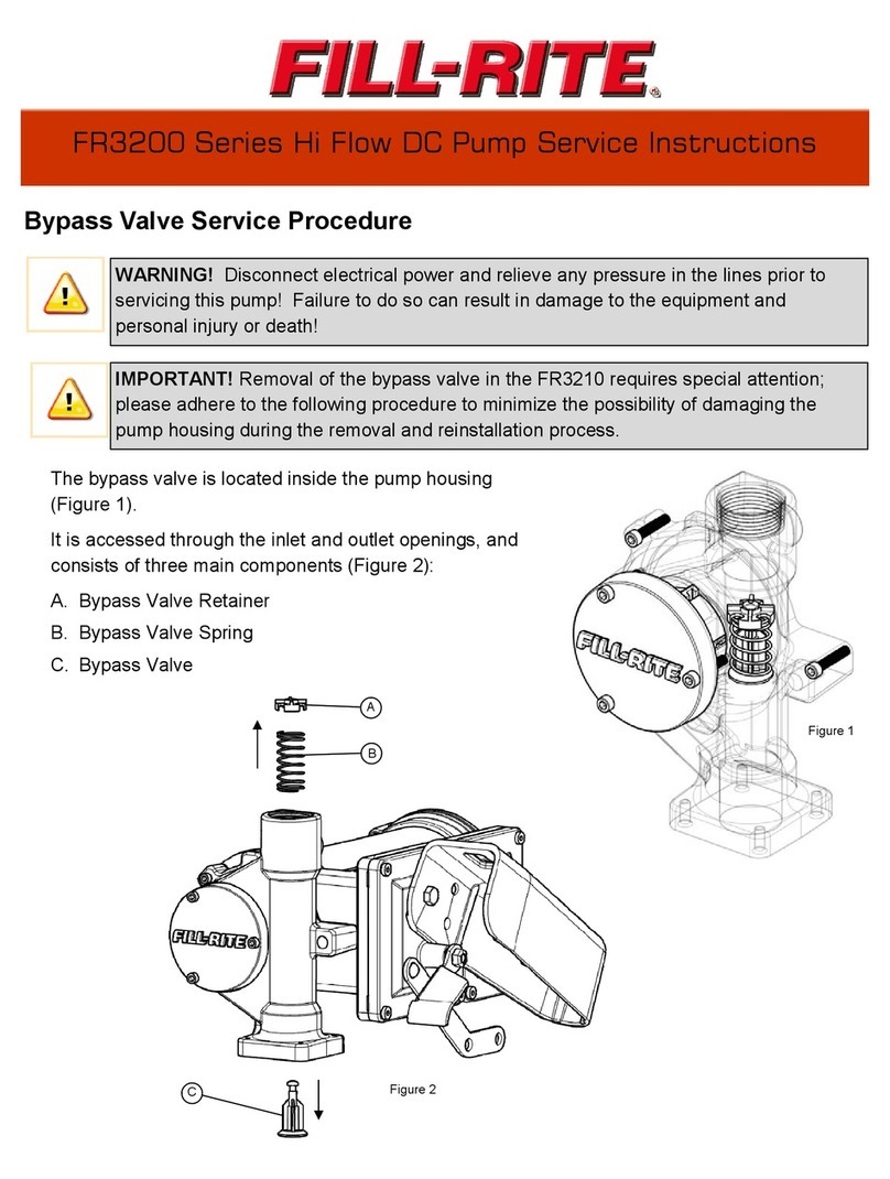
FILL-RITE
FILL-RITE FR3200 Series Operating instructions

FILL-RITE
FILL-RITE FR150 User manual
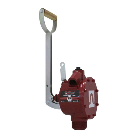
FILL-RITE
FILL-RITE FR150 Instructions for use
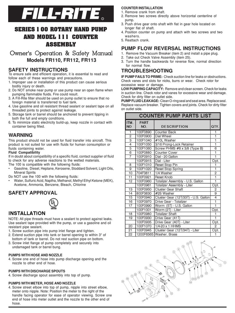
FILL-RITE
FILL-RITE FR110 User manual
FILL-RITE
FILL-RITE RD Series User manual

FILL-RITE
FILL-RITE FR300V Series User manual

FILL-RITE
FILL-RITE FR1600 Series User manual

FILL-RITE
FILL-RITE FR100 Series User manual
FILL-RITE
FILL-RITE FR100 Series User manual

FILL-RITE
FILL-RITE FR100 Series User manual
