Aquathem 10001-5 User manual

MANUAL CONTENTS
This manual provides a detailed step-by-step pro-
cedure for the installation of an Aquatherm
Industries solar pool heating system. If the direc-
tions are followed correctly and only recommended
Aquatherm Industries hardware and components
are used, the installed system should provide years
of trouble free service, savings, and enjoyment.
CAUTION: SOLAR COLLECTORS ARE OFTEN INSTALLED
ON THE ROOFS OF BUILDINGS. UNLESSYOU ARE VERY
FAMILIAR WITH WORKING ON ROOFS AND HAVE THE
PROPER LADDERS AND SAFETY EQUIPMENT FOR
SUCH WORK, YOU SHOULD HIRE SOMEONE WITH THE
NECESSARYEXPERIENCE TODO THE INSTALLATION.
FAILURETO OBSERVE SAFE PRACTICES ON A ROOF OR
OTHER ELEVATED STRUCTURE MAY RESULT IN FALLING,
LEADING TO SERIOUS INJURY TO YOU.
•SAVE INSTALLATION TIME AND AVOID CALL-BACKS •
•READ THIS MANUAL BEFORE MOUNTING COLLECTORS •
SWIMMING POOL
SOLAR HEATING SYSTEMS
INSTALLATION MANUAL FOR
AQUATHERM INDUSTRIES
SOLAR COLLECTORS
FOR MODEL NUMBERS:
10001-5
10001-2
10001-1
10204-12
10204-10
10204-08
16104-12
16104-10
16104-08
16204-12
16204-10
16204-08
16404-12
16404-10
16404-08

2
MOUNTING
COMPONENTS
DIAGRAM
MOUNTING COMPONENTS
This section provides descriptions and part numbers of the
Aquatherm Industries Installation Kits required for each
solar pool heating system. The mounting location of each
kit component is shown by the corresponding circled num-
ber in the ‘Mounting Components’ diagram, shown above.
The Collector Installation Kit (Part #12034-1 for 1 1/2” kit;
#12034-2 for 2” kit) contains the parts needed to fasten a single
solar collector to a supporting surface and to make water connec-
tions from one collector to another. Hold-down strap is not includ-
ed and must be ordered separately Use one (1) kit per collector.
1
PartNo Qty 1 1/2” Qty 2” Description
10008-1 1 __ Outlet header hold-down bracket assembly
10008-2 __ 1 Outlet header hold-down bracket assembly
50006 2 2 Hold-down strap bracket
60648-1 2 __ Collector connector hose (3 3/4” long)
60648-2 __ 2 Collector connector hose (3 3/4” long)
60546-1 4 __ Hose clamp, stainless steel
60546-2 __ 4 Hose clamp, stainless steel
The System Kit (Part #12135-1 for 1 1/2” kit; #12135-2
for 2” kit) contains additional hold-down hardware, connec-
tion parts and adapters needed to complete water connec-
tions from the collectors to the system feed and return line.
The pipe adapters that connect the system piping to the col-
lectors are high temperature CPVC. The system check
valve is 1 1/2” - 2” PVC. Installation and homeowner man-
uals are also included. Use one (1) kit per system.
2
PartNo Qty 1 1/2” Qty 2” Description
10003-1 1 __ Vacuum Relief Valve
10003-2 __ 1 Vacuum Relief Valve
10008-1 1__ Outlet header hold-down bracket assembly
10008-2 __ 1Outlet header hold-down bracket assembly
10011 4 4 Hold-down strap clamp assembly
30061-1 1__ End cap
30061-2 __ 1End cap
30089-1 2 __ Pipe adapter
30089-2 __ 2Pipe adapter
50006 22Hold-down strap bracket
60649-1 2 __ System connector hose (7” long)
60649-2 __ 2System connector hose (7” long)
60546-1 4__ Hose clamp, stainless steel
60546-2 __ 4 Hose clamp, stainless steel
60019-2 11Check Valve (1 1/2” & 2”)
19001 11Installation Manual
----- 1 1 Owner’s Manual

Double Hole Outlet Header Bracket (Part #50069) may
also be used to terminate a strap run in high wind areas where
extra hold-down strength is required.
3
Hold-Down Strap isrequired to secure collectors to
the mounting surface. Use strap 10035-1 (54’) for rows of
up to 6 collectors or strap 10035-2 (107’) for rows of up to
12 collectors. Available in bulk, 1400 ft. roll. Part #10040.
3
The Row Spacer Kit (Part #12017-1 for 1 1/2” kit; #12017-2
for 2” kit) is used when a row of collectors must be interrupted by
aspace to allow for obstructions such as a chimney or roof vent.
It contains the hardware needed to space around any width
obstructions by connecting appropriate lengths of PVC pipe to
the pipe adapters at the inlet and outlet headers of the two col-
lectors on either side of the obstructions. Use when required.
5
The Add-A-Row Kit (Part #12043-1 for 1 1/2” kit; #12043-
2for 2” kit) is used when more than one row of collectors is to
be installed. Use one (1) kit for each collector row after the first.
4
6
The Aluminum Header Clamp Assembly (Part #30171-1 for
11/2” only) is used as supplemental outlet header mounting in
conjunction with the Outlet Header Hold-Down Bracket assembly
(Part #10008-1). The bracket is designed for installations that
require more flexibility for the outlet header mounting hardware
location, such as barrel tile roofs or installations that require addi-
tional mounting hardware to be anchored into rafters or beams.
PartNo Qty 1 1/2” Qty 2” Description
10003-1 1 __ Vacuum Relief Valve
10003-2 __ 1 Vacuum Relief Valve
10008-1 1 __ Outlet header hold-down bracket assembly
10008-2 __ 1 Outlet header hold-down bracket assembly
10011 4 4 Hold-down strap clamp assembly
30061-1 1 __ End cap
30061-2 __ 1 End cap
30089-1 2 __ Pipe adapter
30089-2 __ 2 Pipe adapter
50006 2 2 Hold-down strap bracket
60649-1 2 __ System connector hose (7” long)
60649-2 __ 2 System connector hose (7” long)
60546-1 4 __ Hose clamp, stainless steel
60546-2 __ 4 Hose clamp, stainless steel
PartNo Qty 1 1/2” Qty 2” Description
10008-1 1 __Outlet header hold-down bracket assembly
10008-2 __1 Outlet header hold-down bracket assembly
10011 4 4 Hold-down strap clamp assembly
30089-1 4 __ Pipe adapter
30089-2 __ 4 Pipe adapter
50006 2 2 Hold-down strap bracket
60648-1 2 __ Collector connector hose (3 3/4” long)
60648-2 __ 2Collector connector hose (3 3/4” long)
60546-1 4 __ Hose clamp, stainless steel
60546-2 __ 4 Hose clamp, stainless steel
The Optional Supplemental System Isolation Kit
(Part #12033-5) includes a 1 1/2” - 2” PVC union ball
valve and a 1 1/2” -2” PVC check valve to permit manu-
alisolation of the solar system from the pool or spa fil-
tration system. Use one (1) kit per system.
2A
Aluminum Mounting Bracket & Header Clamp Assembly
7
The Aluminum Header Clamp Assembly (Part #10117-1 for
11/2”; #10117-2 for 2”) is used the same as the Aluminum
Header Bracket (Part #30171-1) and allows for collector
replacement without disturbing the roof penetrations.

4
Figure 1
ASSEMBLY ON
ROOF DIAGRAM
DISTANCE BETWEEN PANEL
HEADERS AND STRAPS
MOUNTING THE SOLAR COLLECTORS
Refer to Figure 1 throughout this section. When mounting
the collectors, always make provisions for inlet connec-
tions at the bottom header and outlet connections at the
top. The outlet headers must be pitched a vertical dis-
tance of at least 8” (20cm) above the inlet headers to
assure proper drainage and uniform flow. Plan the col-
lector location to allow at least one foot on all sides of the
row of collectors for mounting brackets and piping. The
outlet pipe for each row of collectors must be connected
diagonally opposite the inlet pipe. Refer to Figure 2.
Collector
Panel Size
in feet
_________
12
10
8
6
4
Collector
(A) Distance
inches (cm)
_________
60 (152)
48 (122)
36 (91)
24 (60)
_____
Collector
(B) Distance
inches (cm)
_________
16 (40)
Figure 2
Header Inserts (Part #50055-1 for
11/2”; #50055-2 for 2”) are used
in special situations where
unusually high stagnation
temperatures are expected,
such as in a desert climate
or where abnormally high
system pressures may occur.
Use four (4) inserts per collector.
8
The Optional Supplemental High Wind Area
Collector Hold-Down Kit (Part #12035-1 for 1 1/2”,
#12035-2 for 2”) used in addition to the basic collector
installation kit in regions where high winds are prevalent.
Requires twice the amount of hold-down strap.
9

5
1) Determine the position of the last outlet header hold-
down bracket for the row of collectors. Mark this point on
the roof. The collector outlet headers will be located approx-
imately 1” (25mm) below this mark. Refer to Figure 3.
2) Using this point, snap a chalkline to the opposite end
of the row. Slope this line down the roof toward the inlet
approximately 1” (25mm) for each 6 collectors in the row.
Using a 1/8” (3mm) drill bit (for 1/4” (6mm) diameter
screws) drill a hole for the first outlet header bracket on
the first roof mark. Measure up 1” on center from the first
pilot hole and drill pilot hole for second screw. Repeat this
process all along the chalkline for the total number of col-
lectors to be installed.
3) Inject a generous amount of high quality sealant into
each hole and onto the surrounding roof surface. Bolt all
the outlet header hold down brackets to the roof as
shown in Figure 4.
4) Locate the hold-down strap bracket holes using the
information in Fig. 1, Table A. Measuring from the top
outlet header bracket chalk line, snap another chalk line
parallel to this line using the “A” dimension. The “B”
dimension is the same for all collector sizes, which is 16”
(40cm) up from the outside of the bottom header and can
be measured after the collectors are installed. Wait to
install the hold-down strap brackets until after the collec-
tors are installed so as not to damage the collectors
when you are bringing them to the roof for installation.
5) Bring the first collector to the roof and slip the proper
hoses over both ends of the inlet and outlet headers on
the last return collector.Make sure that the side of the
collector with the serial number label on it is facing down.
The long hoses go on the outlet of the last collector and
the inlet of the first collector.Push UP TOthe hose locat-
ing shoulder, but NOT OVER it. Locate a hose clamp
3/8” (10mm) from the end of the hose in order to center
it on the header groove. This clamp must face up so as
to be accessible for tightening and will not rub against the
mounting surface. Make sure you securely tighten each
clamp with a nutdriver. If a nutdriver is not available, a
‘hex’ wrench or screwdriver will suffice. THE HOSE
CLAMPS MUST BE LOCATED OVER THE GROOVES
IN THE HEADER.
6) Position the collector on the roof so that the center of
the outlet connection hoses are directly beneath the
secured outlet header brackets and slip the bracket hold-
down clamps over the connection hoses. Lightly tighten
the clamp around the header hose. Refer to Figure 5.
Continue to install all the collectors in the array,coupling
them side to side.
7) If theAluminum Header ClampAssembly is to be used
for supplemental mounting hardware, install them after
both the outlet header brackets and the collectors have
been installed.
Figure 5
Figure 3
Figure 4

6
7) Proceed to the lower chalk line previously snapped on
the roof for the hold-down strap brackets. Mark a hole 2”
(5cm) to the side of the first collector and continue mark-
ing holes on the chalkline centered exactly between the
absorber surfaces until you reach the last collector.
Mark the last hole the same 2” (5cm) to the side of the
last collector. Drill a pilot hole and apply sealant at each
of these locations. Bolt the hold-down strap brackets on
the roof. Refer to Figure 6. It is OK to step on the col-
lectors as long as you stay one foot away from the top
and bottom headers. Mark the holes for the bottom hold-
down strap by measuring up 16” (40cm)from the outside
of the bottom header and again centering them between
the absorbers and 2” (5cm) away from the first and last
collector.
Slip one end of a hold-down strap through the slot in the
hold-down strap bracket at the end of the row,then through
the strap clamp and out through the other slot in the hold-
down bracket. Pull about 3” (7-8cm) of the strap through
and bend it back toward the clamp. Refer to Figure 7.
Slip the loose end of the strap through the strap clamp
and pull it tight. Clamp screw (A) should be tightened
securely,but not over-tightened to the point where the
clamp is distorted. Refer to Figure 8. Bring the remain-
ing strap end across the collector face, passing through
both slots in the bracket located on the other side of the
collectors. Pull the straps taut against the face of the
collector. Repeat this procedure for the remaining hold-
down strap. Refer to Figure 9.
8) Install the vacuum relief valve in the outlet header of
each row. This will be located at the opposite end of the
row that is connected to the collector outlet pipe. Refer
to figure 2, 11, and 12.
9) Install an end cap in the inlet header of each row,
opposite the end that is connected to the collector inlet
pipe. Refer to Figures 2, 11, and 12.
10) INSPECT THE INSTALLATION AND CHECK ALL
CLAMPS FOR PROPER POSITION ANDTIGHTNESS.
Installation Over Roof Vent Pipes
Collector models with intermittent sonically welded plates
can be installed over or around different diameter roof vent
pipes or other obstructions up to 2” (63mm) in diameter.
After snapping the top chalk lines but before marking and
pre-drilling for your outlet header brackets, locate the seam
in the collector nearest to where the vent pipe is to come
through. Separate by pulling up on top plate, and pushing
down on the lower plate. Should the vent pipe protrude
near a sonic tack weld, it will have to be cut apart. Using a
sharp utility knife, cut through the weld while pulling the two
plates apart. Lay the collector over the vent pipe, keeping
the vent pipe at least 12” (30.5cm) away from a header. It
will be easier to complete an installation by mounting this
collector first and then working away from it.
Figure 6
Figure 7
Figure 8
Figure 9

7
Figure 10
PLUMBING
SYSTEM
SCHEMATIC
With a roof vent pipe of 3” (8cm) in diameter, the collec-
tors can be positioned on either side of the vent. Two sys-
tem connector hoses (Part #60649-1/-2) can be employed
to couple the collectors together for vent pipes or other
obstacles up to 7” (17cm) in diameter. Mark your 51”
(1.3m) centers wherever the outlet header brackets ‘fall’
on the upper chalk line. With obstructions of over 7”
(17cm), such as attic fans and skylights, lay out the col-
lectors on either side of the obstruction using a Row
Spacer Kit (Part #12017-1 for 1 1/2”; #12017-2 for 2”).
System Piping
Refer to Figures 10 & 11, throughout this section. The
most common piping configurations use a pressure filter.
The pump draws the water from the skimmer and/or a
main drain, forcing it through the filter and sending it back
to the pool through the return lines.
If a fuel-fired heater is installed, it is located between the fil-
ter and the return line to the pool. The pipes to and from the
solar collectors are connected to the return line to the pool
before the water enters the fuel-fired heater, if one is used.
Whenever there is more than 40 gpm (151.6l)required
flow rate to the collectors or more than 100’ (12m) of pip-
ing used in a system, install 2” (63mm) piping to and from
the collectors.
Piping to and from the collectors should be the same type of
plastic piping and fittings approved for use with swimming
pool filters and pumps. It is recommended to always use
Schedule 40 PVC pipe and fittings. Although PVC pipe is
generally white, black is also available but may be difficult to
find locally. If for aesthetics black pipe is desired it can
always be painted black. Use a PVC cutter or a PVC wide-
blade saw (not a hacksaw) for cutting pipe. It is important to
use both a quality cleaner/primer and solvent in gluing a PVC
joint. For more detailed information on PVC gluing refer to
Engineering Bulletin No. 8701. Finally, use a cloth while
either gluing or painting to keep the job a clean one. Piping
should also be supported at intervals of 5’ (1.5m) for hori-
zontal pipe and 8’ (2.5m) for vertical pipe. Use either galva-
nized or plastic pipe clamps. Aquatherm Industries outlet
header bracket assemblies (Part #10008-1/-2), which are
made of stainless steel, are also excellent pipe hangers.

8
Manual Systems
Some systems can employ a manual control valve to con-
trol the flow of water thru the solar collectors, although this
may reduce the overall heating capacity of the system.
The manual control valve usually consists of a non-posi-
tively sealed 3-way valve as shown in Diagram 10. Water
continuously flows through the solar collectors when the
filter pump is on, but can be diverted manually by the pool
owner if the pool becomes too warm or during extended
cloudy weather. During a threat of freezing conditions it
can also be diverted, by first shutting off the pool pump,
allowing the collectors to drain, diverting the 3-way manu-
al valve to the “bypass collector” position and shutting the
isolation valves on the collector feed and return lines. A
lower end cap on the collectors or any of the connecting
hoses can be removed to make sure there is no standing
water in the collectors. The filter pump can then be re-
started to allow for normal pool filtration.
During normal operation of the system when the 3-way
valve is in the ‘bypass collector’ position all the water in the
collectors should drain back through the 3-way valve (non-
positively sealed) when the filter pump shuts off. An alter-
nate way to protect against sudden freezes can be accom-
plished by running a bypass line (1/8”-1/4”, 3-6mm)
between the collector feed and return line above the isola-
tion valves, if any. It is possible that a small amount of water
may be present in the collectors when a non-positively
sealed 3-way valve is used and the filter pump is on. If a
positively sealed 3-way valve is used, a bypass line as men-
tioned above is mandatory to allow for collector drainage.
AUTOMATIC CONTROL SYSTEMS
The performance of a solar pool heating system can be
improved with the use of an electronic control and motor-
ized 3-way valve. The control activates the motorized
valve and either sends water thru the collectors for heating
(or nocturnal cooling) or automatically bypasses the collec-
tors when the pool is warm enough or insufficient sunlight
is available. Refer to the manufacturer’s instructions
included with the automatic control you use.
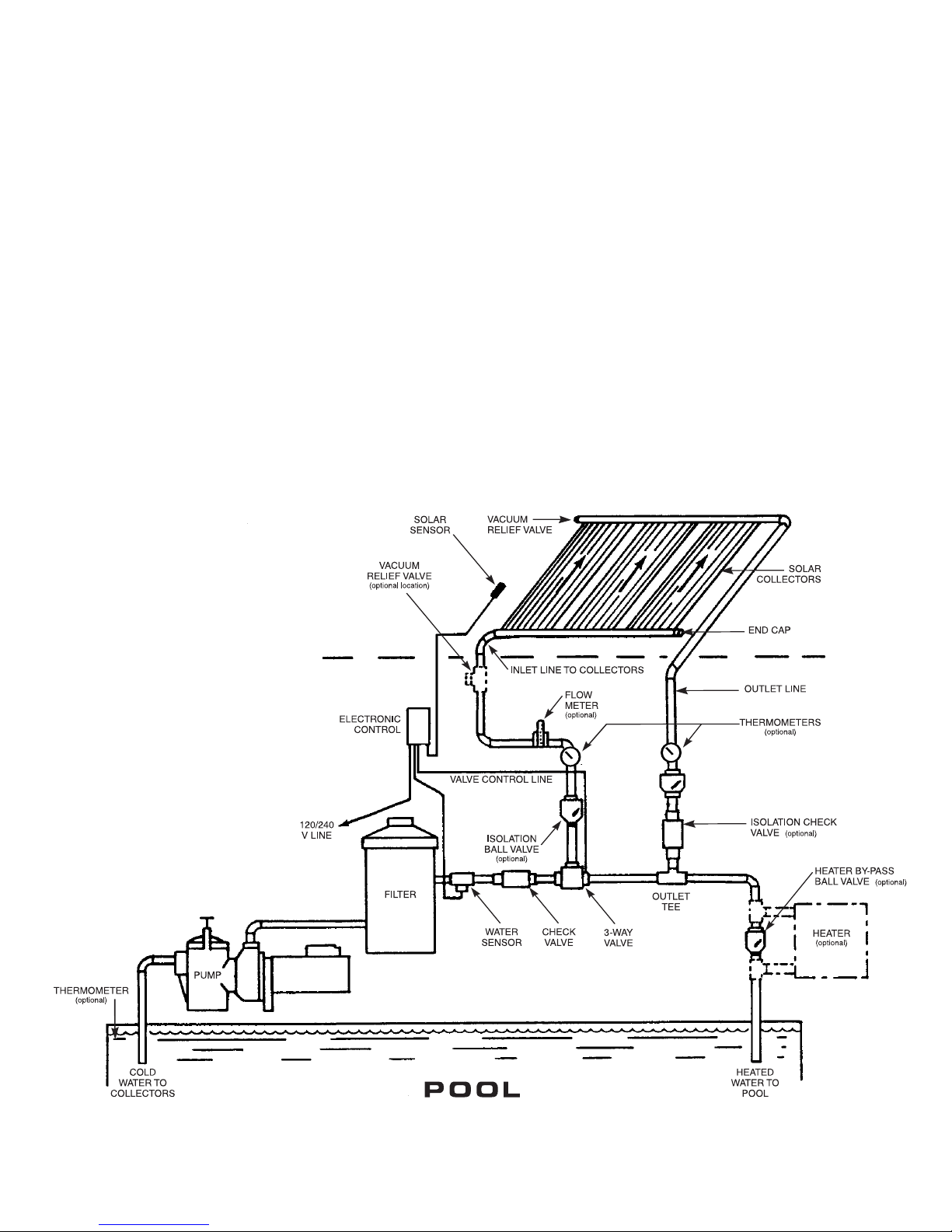
Other Equipment
Some pools employ an automatic pool cleaner.This
should be plumbed before the control valve to assure
positive flow to the cleaner at all times. If the pool uses
an automatic chlorinator,this should be plumbed after
the outlet tee on the return to the pool.
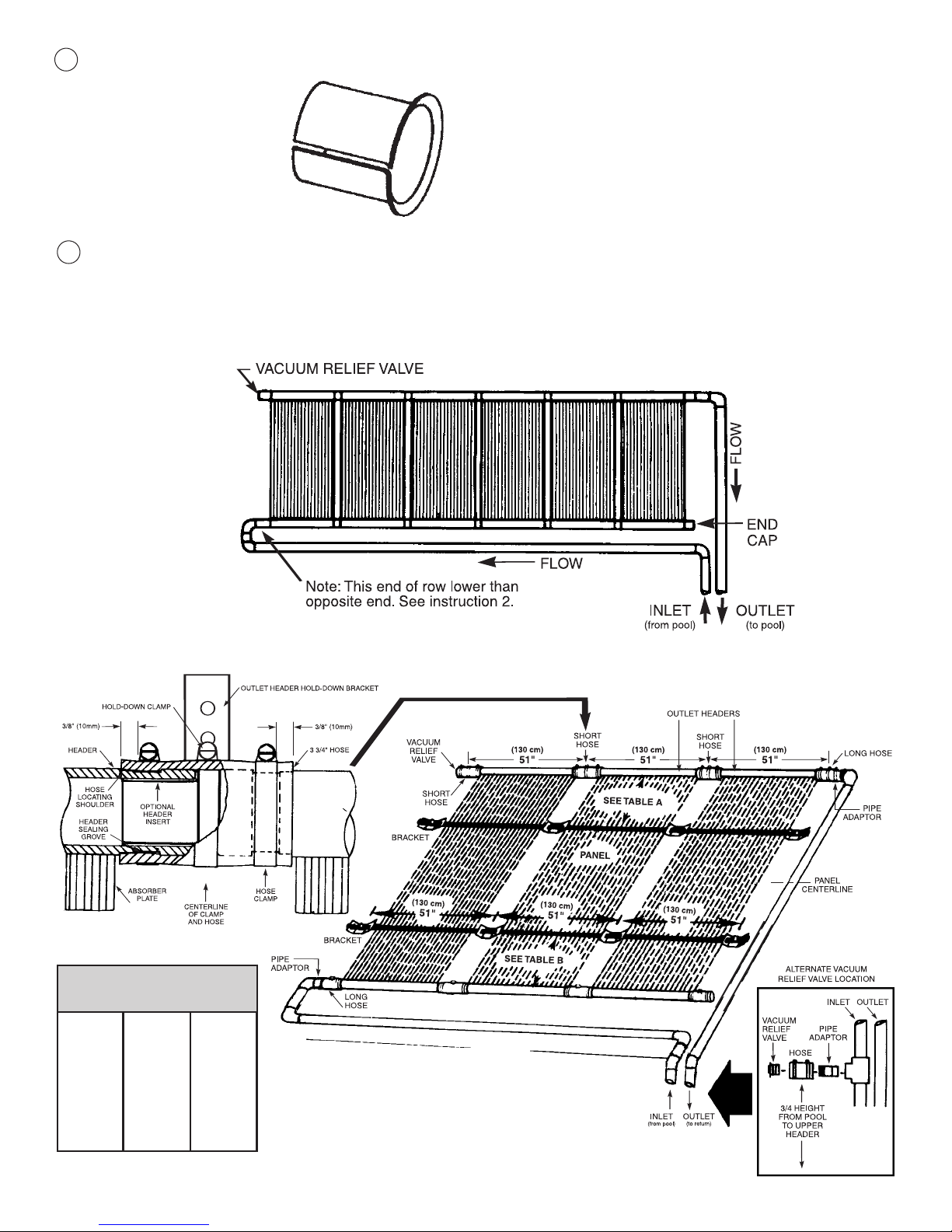
Flow Rates
In order to receive optimum results from Aquatherm
Industries collectors, the following recommended flow
rates and number of collectors per row should be followed.
When the system is running, all the collectors should feel
uniformly cool to the touch, and there should be no resid-
ual air left in the pool return lines. If either of these two
conditions persist, chances are that the flow rates thru
the collectors are inadequate or the system is not prop-
erly balanced. A flow meter can be installed in the col-
lector feed line to check on the flow rate. If the flow rates
are within the limits as shown in Table B, then the sys-
tem may not be properly balanced, especially with sys-
tems requiring multiple banks of collectors. Refer to the
following section on Special System Layouts.
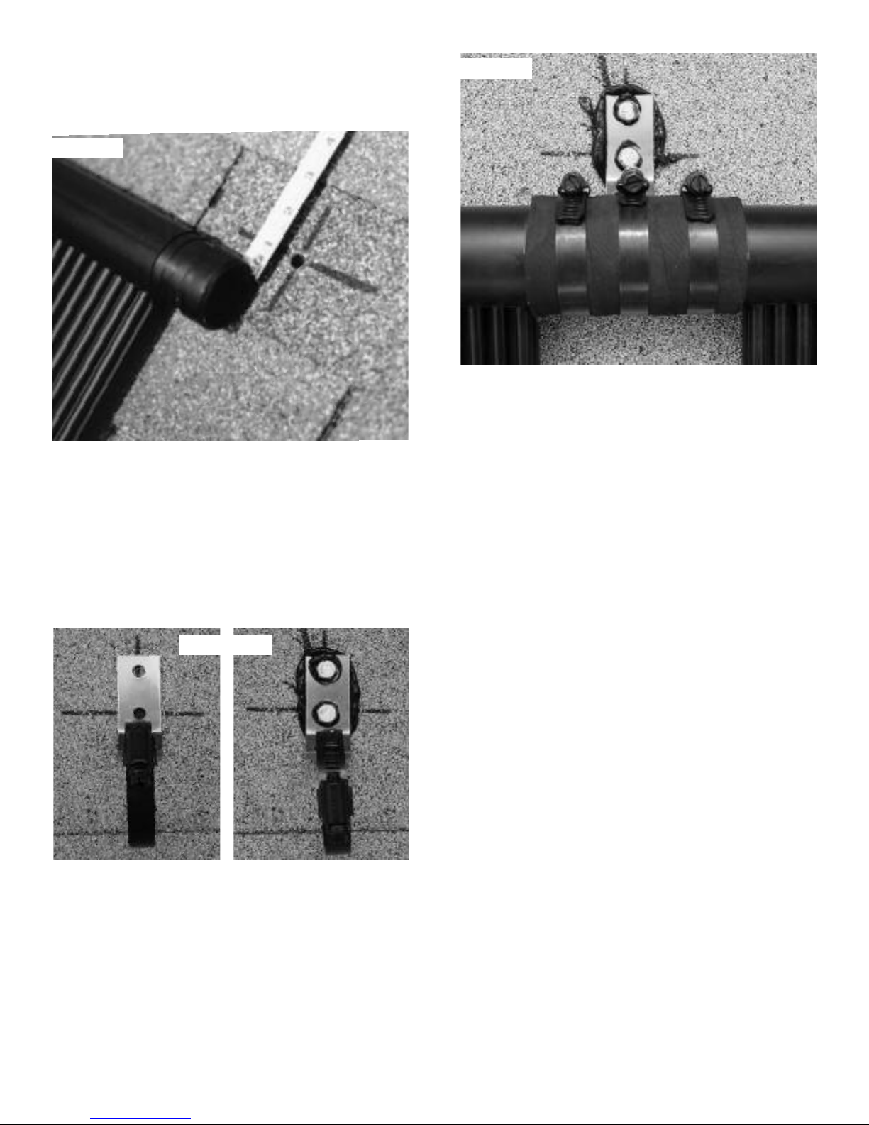
If the flow rate is below the minimum as shown in the
table above, then the pool pump horse power or pipe
size should be increased, or a booster pump installed in
some cases. If the long hoses on the inlet and outlet pip-
ing connections “suck in”, then slip a piece of 1 1/2”
(50mm) pipe into the hose to prevent this. And also, if
the flow rate is excessive (more than 10 GPM/(37.9l)
collector), or if the system pressure is greater than 30
psi, a bypass line should be installed between the col-
lector feed and return lines above the 3-way valve to pre-
vent problems with the collectors and connection hoses.
If there is residual air in the pool return lines and the col-
lectors do feel cool to the touch, refer to the section con-
cerning the vacuum relief valve test on page 10.
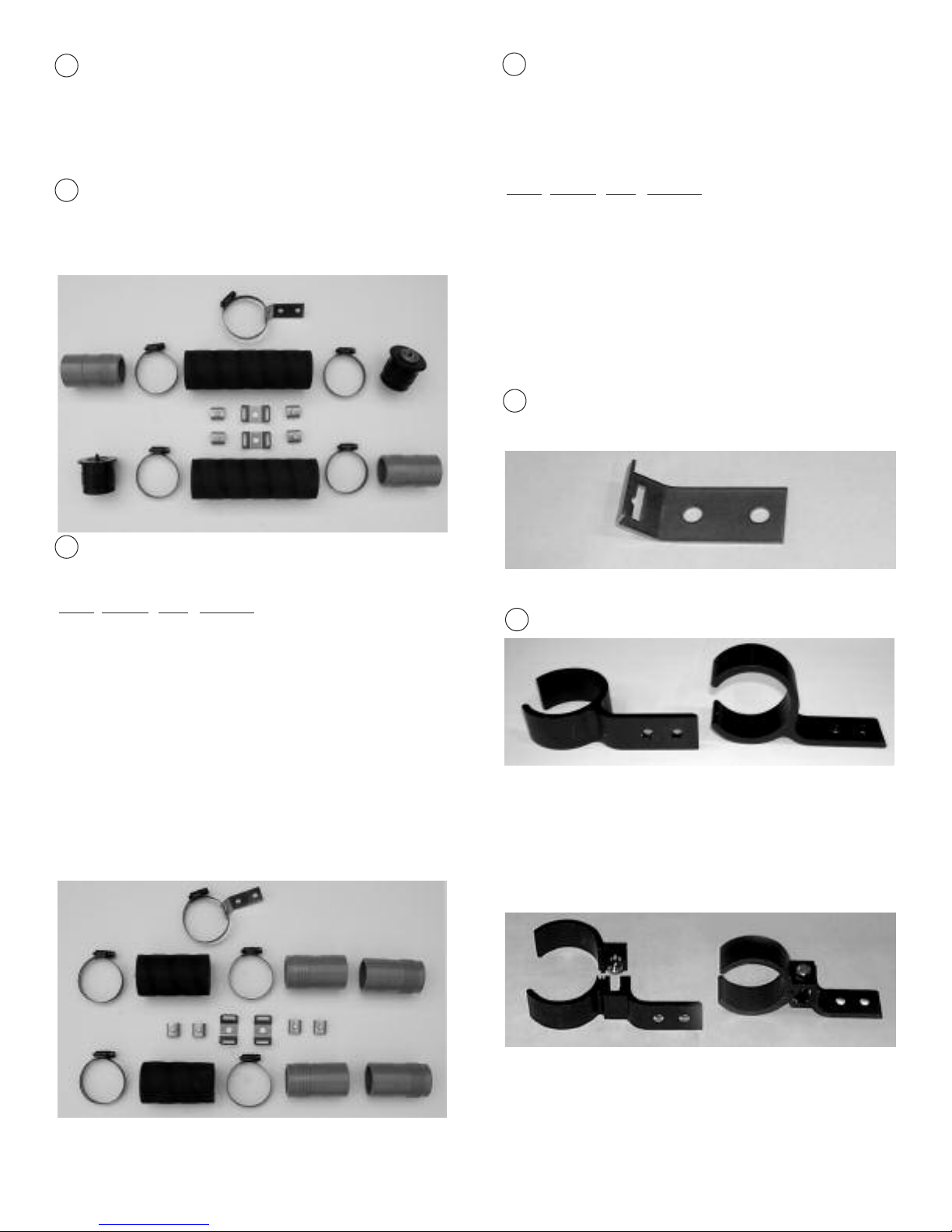
Optional Isolation Valves
Isolation valves may be installed in the collector piping
so that the pool may be operated while the collectors are
being serviced or during freezing weather. Install a man-
ually operated ball valve in the collector inlet line and a
check valve on the collector return line. Both valves,
available in the Optional Supplemental System
Isolation Kit (Part #12033-1) are made to accept either
11/2” or 2” PVC pipe. Make sure that the arrow on the
check valve is pointing away from the collectors, and that
the ball valve and check valve are located close to the
control valve and outlet ‘T’, respectively.For further pre-
cautions in warm climates where pools are operated
year round and periodic freezes can occur, a bypass line
(small diameter tubing) can be located above the ball
and check valve so as to prevent any accidental trapping
of water in the collectors by the pool owner. To make
sure no water is left in the collectors for servicing or dur-
ing freezes, remember that the pool pump should be
shut off, allowing the collectors to drain naturally, before
the optional isolation valves are used.
COLLECTOR SIZE
4x12 4x10 4x8
Recommended flow rate per collector, gpm/
l
5.0/18.9 4.0/15.1 3.25/12.5
Minimum flow rate per collector, gpm/
l
3.0/11.4 2.5/9.5 2.0/7.6
Maximum # collectors per row 10 12 14
Table B

9
Figure 11
DIVIDED
SYSTEM
ASSEMBLY
ON ROOF
Special System Layouts
Use a divided system when installing more than the rec-
ommended maximum number of collectors per row,
when avoiding roof obstructions, or where limited space
dictates. This provides uniform distribution of water
through all the collectors. If water distribution through the
collectors is non-uniform, the heating capacity of the sys-
tem will be reduced.
WHEN INSTALLING A DIVIDED SYSTEM, THE OUT-
LET HEADERS FROM EACH OF THE LOWER (OR
CLOSEST) ROWS OF COLLECTORS MUST BE CON-
NECTEDTOTHE HIGHEST (OR FURTHEST) POINT IN
THE SYSTEM. Refer to Figure 11.
A divided system requires an Add-A-Row Kit (Part
#12043-1/-2) for each row of collectors.
A more complex divided system is shown in Figure 12.
This also illustrates the application of the Row Spacer Kit
to clear a roof obstruction.
Booster Pump System
In some cases, the pool filter pump may not be able to cir-
culate water at a high enough flow rate to allow for proper
collector operation. If so, it may be necessary to replace
the filter pump with a larger one or add a booster pump. If
the pump size is increased, it may also be necessary to
upgrade the filter with one with greater flow ratings.
Supplemental Gas, Oil-Fired,
or Electric Heaters
It is desirable to pipe the stand-by heater in a bypass
loop. Refer to Figure 10. Fuel-fired heaters often create
alarge pressure drop. By placing a heater in a by-pass
loop, pump size, and electrical energy requirements may
be reduced.
SYSTEM START-UP AND TEST
System Start-up and Checkout for
Automatic Systems
To check out the system for proper operation turn on the
filter system. Set the temperature control to its highest
level. Switch the control to the “flow through collector”
mode. The “flow through collector” light should come on.
The 3 way valve will then be sending water thru the col-
lectors, and air will be purged out of the collectors into the
pool return line for several minutes, and should then clear.
The collectors should feel uniformly cool to the touch.
Switch the control to the “bypass collector” mode. The cor-
responding light will go on and the 3 way valve will be
sending water directly back to the pool, bypassing the
solar collectors. After about 5-10 minutes, feel the solar
collectors again. They should have begun to warm up.
Now switch back to the automatic mode. If the sun is still
shining on the solar collectors, the “flow thru collector”
light should go on again. Adjust the temperature control
lower.
When you reach the actual temperature of the pool
water,the light will turn off. The flow bypass collector
light will go on again. Move the temperature control to
maximum and leave there. The “flow through collector”
light will go back on. For more detailed information on
the system startup, trouble shooting and valve/control
installation, follow the manufacturers’ instructions includ-
ed with the automatic control system.

10
Figure 12
Manual Control of System
To test collector operation, follow either the flow-rate or
temperature-rise procedure. Divert water through the col-
lectors. Turn on the pump and either observe flow rate or
temperature rise. The flow rate or temperature rise would
be the same as that specified in the “System Start-Up and
Test” section. If it is not, then check for the indicated prob-
able causes and make necessary corrections.
FlowRate Test Method
The preferred system test method is flow rate. This is also
the easiest and quickest method. To check flow rate, install
aflow meter in the inlet line to the collectors (follow instal-
lation instructions provided with the flowmeter).
Temperature RiseTest Method
An alternate test method is temperature rise. Toprepare
the system for testing, obtain two accurate thermometers.
Aquatherm Industries dial thermometers (Part #60054-2)
are excellent for this application. One of these ther-
mometers is installed in the outlet line from the collectors
as shown in Figure 10. The other is used to check the
temperature of the pool water, to compare it with that of
the water leaving the solar collectors. Before installing
the thermometer in the outlet line, immerse both ther-
mometers in the pool water for several minutes to com-
pare the temperature readings. If they are not identical,
make a notation of the difference and add or subtract (as
appropriate) this difference to or from the reading taken
while you are testing. This is necessary in order to pro-
vide an accurate indication of the temperature rise of the
water passing through the solar collectors.
Turn the pump on and move the flow switch to the “COLL”
position. Observe valve action...it should divert water
through the collectors. After flow through the collectors has
continued for a least fifteen minutes, compare the pool
water temperature with the temperature of the water flow-
ing through the outlet line. On an average sunny day, with
the air temperature approximately 700F(210C) the water
leaving the collectors should be 1 to 70F(1 to 40C) higher
than that in the pool. If the water rise is greater than this,
insufficient water is flowing through the collectors. This
may be caused by a clogged filter, undersized piping, to
many elbows in the piping or an inadequate pump. It is
important that the temperature rise through the collec-
tors be kept as low as possible in order to deliver the
maximum amount of heat to the pool.
Vacuum Relief Valve Test
When the solar system is first turned on, air in the collec-
tors will be expelled into the pool and bubbles will appear.
The appearance of bubbles in the pool should stop after
afew minutes. If, after a few minutes, bubbles continue
to be discharged at the return to the pool,remove the vacuum

11
relief valve(s) and replace it with and end cap. Relocate
avacuum relief valve to a position in the inlet piping
which is at a height of approximately three-fourths of the
elevation of the collectors above the pool. Refer to
Figure 1.
(A quicker alternate method is to first try to reverse the
end cap and the vacuum relief valve on the collector
array to see if this stops the bubbles in the return lines.
Sometimes the end cap is about 3/4 of the elevation of
the collectors and this is a lot quicker than cutting in a tee
in the supply pipe.)
MAINTENANCE
Winterizing Procedures
The solar collectors should drain automatically each time
the pump cycles off. There are no special requirements
for winterizing the solar collectors. The pool piping
should be winterized as per your normal practice. In
southern parts of the country pool owners operate their
pools throughout the winter although light freezing condi-
tions may occur. The accepted procedure for avoiding
freezing of the pool piping and filtration system has been
to continuously circulate the water. When solar heaters
are used on a pool under these conditions, anti-freeze
precautions should be taken.Aquatherm Industries solar
collectors are not normally affected by light freezing.
However,in order to protect appurtenant components
such as end caps and pipe fittings and the collectors
against unusual or severe freezing conditions, one of the
following two procedures should be followed when freez-
ing weather is imminent.
1. Turn circulating system offand allow solar collectors
and piping to drain. Isolate collectors with gate or ball
valve in collector feed line and a check valve in the col-
lector return line. Switch the solar control to the bypass
position. The pool filtering system may then be turned
back on. When freezing conditions have passed, open
isolation valves and switch the solar control to “AUTO”.
2. Switch the solar control to the “COLL” position so that
water circulates through the collector. When freezing con-
ditions have passed, switch the solar control to “AUTO”.
THIS METHOD IS NOT RECOMMENDED WHERE
TEMPERATURE LEVELS MAY DROP SEVERELY.
Annual Service
Collector Clamps:
Inparticularly hot climates, such as Arizona and
Southern Florida, the clamps which are used to connect
the solar collectors may become loose. If you notice
leaks around the hose couplings, use a nutdriver to tight-
en clamps. Do not tighten to the extent that the pipe col-
lapses or the clamp gears strip. In areas where unusu-
ally high stagnation temperatures are prevalent or where
abnormally high system pressures occur, use header
insert (Part #50055-1/-2).
COLLECTOR REPAIR
This method allows for an easy and permanent on site
repair of a collector by isolating the leaking riser tube.
Referring to the figure below, locate the tube to be isolat-
ed. (End tube has been shown for clarity.) Using a sharp
utility knife, very carefully cut away approximately 1” of
the tube at both headers. Drive a #10 - #12 sheet metal
screw,preferably stainless, into the hole in the header.
The screw must be between 1/2” and 3/4” long. DO NOT
OVERTIGHTEN! If the screw strips out, or if the repair
leaks, use a larger screw.This repair method will not
void the collector warranty.

1940 Rutgers University Blvd.
Lakewood, New Jersey 08701
1-732-905-9002
©2005 Aquatherm Industries Solar Pool Heating SystemsPart No. 19001 Rev. 12/05
Figure 14
BOOSTER PUMP
SYSTEM DIAGRAM
FOR OUTDOOR POOLS
12
This manual suits for next models
14
Table of contents
Popular Swimming Pool Heater manuals by other brands

FMI
FMI Vantage Hearth LBG-18SM OWNER'S OPERATION AND INSTALLATION MANUAL

Raypak
Raypak ELS 1102-2 Illustrated parts list

GAME
GAME SolarPRO 4721 owner's manual

Hayward
Hayward HeatPro installation guide

Thermalec
Thermalec ZENITH RANGE 96kW instruction manual

Pentair
Pentair MiniMax 75 Operation & installation manual