Aquawatt AB13R User manual
aquawatt outboard motor operator’s manual
Version 1.22 EN | 31.03.2015 | copyright by aquawatt ™ | all4solar ™
1
Operator’s Manual
Electric Outboard Motor
AB13R & AB13T POWER
AB22R & AB22T RACING
AB22R - THRUSTER
advanced electric
inboard- and outboard engines
aquawatt Asia - Pacific
all4solar Dominic de Vries ABN 61 832 274 764
123 Harbour Drive | Trinity Park 4879 QLD (Australia)
+61(0)400275866|info@aquawatt.com.au|www.aquawatt.com.au

aquawatt outboard motor operator’s manual
Version 1.22 EN | 31.03.2015 | copyright by aquawatt ™ | all4solar ™
2
Dear Customer
Congratulations! You purchased a high quality product with exceptional performance. To ensure
this for many years, we kindly ask you to read this document carefully and familiarize yourself with
the motor before using it.
This manual has been compiled to help you install and operate your aquawatt motor with safety
and pleasure. It contains details for the motor, all equipment fitted or optionally supplied and
information on its installation, operation and maintenance.
Please note, that incorrect installation and operation can cause severe damages or injuries and will
void any warranty from the supplier.
We wish you a lot of pleasure with this unique „green power“- motor.
Your aquawatt - Team
Please note the following information in this handbook and report these, as well as any change of
ownership to aquawatt (servi[email protected]) within 4 weeks of purchase to register for full
warranty entitlement (see section 8).
Owner: ………………………………….
Phone/Email: ………………………………….
Date of purchase: ………………………………….
Dealer/point of sales: ………………………………….
Serial number (see shaft): ………………………………….
Type: remote tiller
Main use: saltwater freshwater
Check the actual status of any
motor before purchase – send an
email to [email protected]
indicating the serial number.

aquawatt outboard motor operator’s manual
Version 1.22 EN | 31.03.2015 | copyright by aquawatt ™ | all4solar ™
3
Contents
1) Hazard communication .................................................................................................................... 5
1.1 Hazard signs ....................................................................................................................... 5
1.2 Unpacking .......................................................................................................................... 6
1.3 Eligibility of the boat / transom height .............................................................................. 6
1.4 Open hood .......................................................................................................................... 7
2) Installation to the boat ..................................................................................................................... 8
2.1 Installation to the transom ................................................................................................. 8
2.1 Electric power supply ........................................................................................................ 9
2.2 Safety stickers .................................................................................................................. 11
2.3 Warranty information operation / installation ................................................................. 12
3) Installation of remote controlled motors ........................................................................................ 13
3.1) Throttle and gear shift ........................................................................................................ 13
3.2) Steering .............................................................................................................................. 15
3.3) Display & switches ............................................................................................................ 17
4) Operational area ............................................................................................................................. 18
5) Drive with the aquawatt outboard motor ....................................................................................... 18
5.1) Turn-on procedure ............................................................................................................. 19
5.2) Drive forward..................................................................................................................... 20
5.3) Reverse .............................................................................................................................. 20
5.4) Safety Switch ..................................................................................................................... 20
5.5) Multi functional display ..................................................................................................... 20
5.6) Error messages on display ................................................................................................. 22
5.7) Low voltage alert (optional) .............................................................................................. 22
5.8) Trim the motor ................................................................................................................... 23
5.9) Hand throttle ...................................................................................................................... 23
5.10) Steering brake .................................................................................................................. 24
5.11) Power and output ............................................................................................................. 24
5.12) Main fuse ......................................................................................................................... 25
5.13) Swimming & passengers .................................................................................................. 26
6) Maintenance & inspection ............................................................................................................. 26
6.1) Service, spare parts and lubricants...................................................................................... 26

aquawatt outboard motor operator’s manual
Version 1.22 EN | 31.03.2015 | copyright by aquawatt ™ | all4solar ™
4
6.2) Service chart ....................................................................................................................... 29
7) Boat transport & trailering ............................................................................................................. 30
8) Warranty ........................................................................................................................................ 30
9) Technical data ................................................................................................................................ 31
10) Spare parts ................................................................................................................................... 35
11) Installation diagram ..................................................................................................................... 36
12) Propeller information ................................................................................................................... 37
12.1) Choice of propellers ......................................................................................................... 37
12.2) Replace propeller .............................................................................................................. 38
13) High power batteries .................................................................................................................... 39
14) Battery charging / solar power ..................................................................................................... 40
14.1) Standard grid chargers ...................................................................................................... 40
14.2) Charging with solar power ................................................................................................ 40
14.3) Generators ......................................................................................................................... 40
14.4) Solar panels ....................................................................................................................... 41
14.5) Wind generators ................................................................................................................ 42
15) CE conformity declaration for aquawatt electric – outboard motor .......................................... 43

aquawatt outboard motor operator’s manual
Version 1.22 EN | 31.03.2015 | copyright by aquawatt ™ | all4solar ™
5
1) Hazard communication
Before operating your motor you have to carefully read and understand this operator’s manual.
As you read this manual, please note the hazard warnings which alter you to safety precautions
related to unsafe conditions or operating procedures. We have included these warnings because
we are concerned about your safety.
1.1 Hazard signs
DANGER Calls attention to immediate hazards that WILL result in severe personal injury or
death.
WARNING Identifies hazards or unsafe practices that COULD result in severe personal injury or
death.
CAUTION Indicates hazards or unsafe practices that COULD result in minor personal injury or
product or property damage.
INFO Indicates important information for a safe and easy operation or highlights special
circumstances.
For any third party equipment (batteries, switches, fuses, cables etc.) read the operations and instructions
manual as well as the safety recommendations of those suppliers.
If at any point you do not understand this documentation or explanations seem unclear, do not
proceed the installation or operation prior to contacting your aquawatt dealer!
aquawatt outboard motor operator’s manual
Version 1.22 EN | 31.03.2015 | copyright by aquawatt ™ | all4solar ™
6
1.2 Unpacking
WARNING
Do not leave any small parts unattended as small children and animals could drown. Fix the motor
to a stable frame that it cannot fall over. Always to be lifted by two. Always ensure that the skeg is
set on a soft underground.
If any part of the motor is damaged, do not install or operate. Contact your aquawatt dealer.
1.3 Eligibility of the boat / transom height
WARNING
Only install your motor to boats where a maximum motor weight and power (56 kg / AB12/13 or 65
kg / AB 22 or 95 kg AB 22 Thruster) are indicated on the manufacturer specification plate of the
hull.
Do not connect your motor to the battery or start your motor if not fixed to the hull or the
antiventilation plate out of the water.
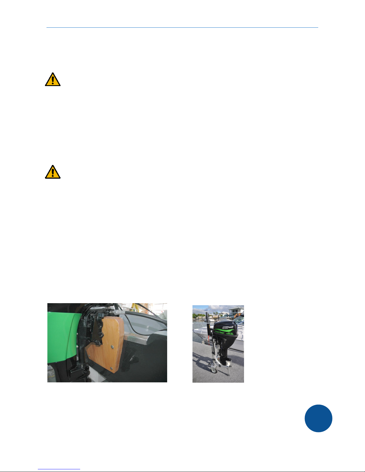
The aquawatt motor is a long shaft motor and fits to a transom height of 20 inches (530-560 mm).
If the transom is too low or to thick for the mounting bracket, an external board can be constructed
to adapt the motor to the transom.
Adapter board
Carry the motor with care and store upright if possible.
Always ensure that the operator has a valid boat license and the boat is equipped with the
necessary safety gear.
aquawatt outboard motor operator’s manual
Version 1.22 EN | 31.03.2015 | copyright by aquawatt ™ | all4solar ™
7
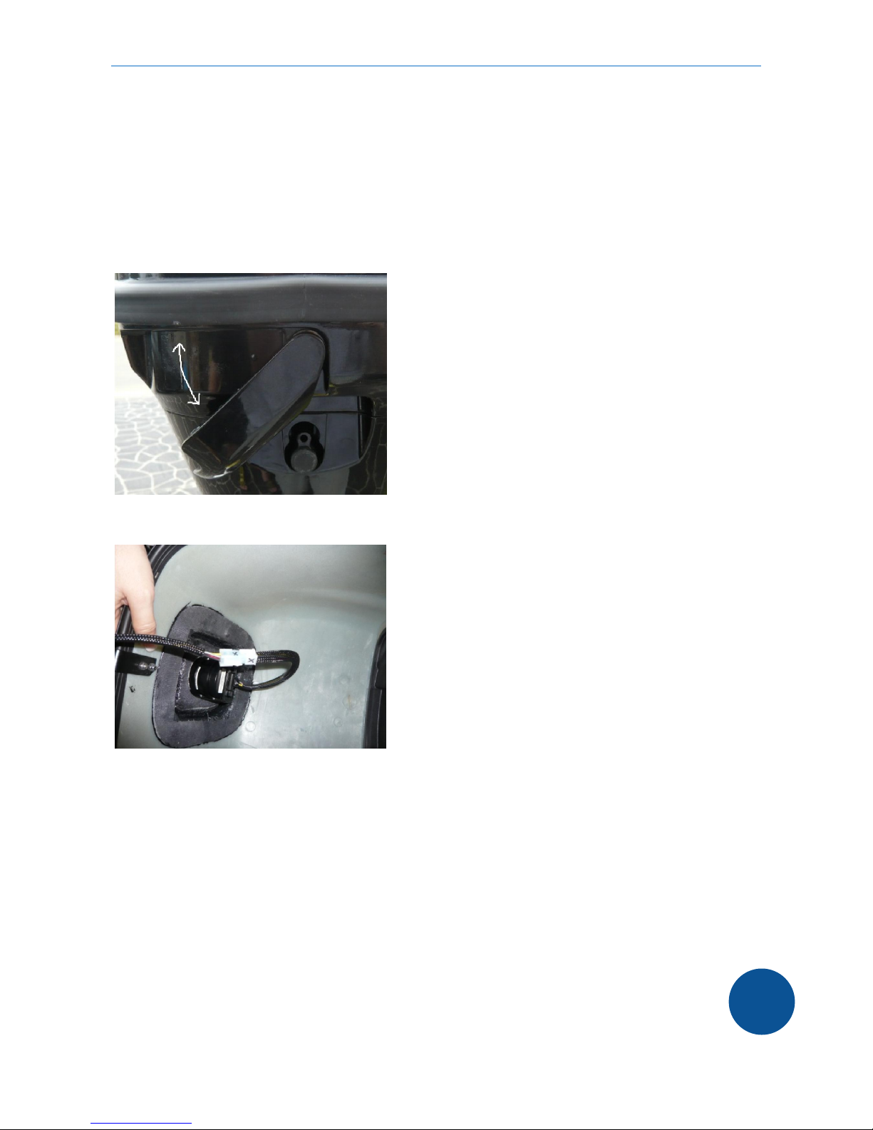
1.4 Open hood
When opening the motor hood, make sure the motor is disconnected from the battery system.
The motor has to be fixed in upright position on a stable construction if any work is executed.
Carefully remove the hood and unplug the connection to the display for the tiller motor.
When reassembled make sure, that the display is connected to the correct plug (mark with X).
Always check the secure attachment to the motor base before you start operating!

aquawatt outboard motor operator’s manual
Version 1.22 EN | 31.03.2015 | copyright by aquawatt ™ | all4solar ™
8
2) Installation to the boat
Place the motor with the mounting bracket to the middle of the transom top. The antiventilation
plate has to be in the water at all times. It should be 20 – 50 mm deeper in the water than the
bottom of the hull.
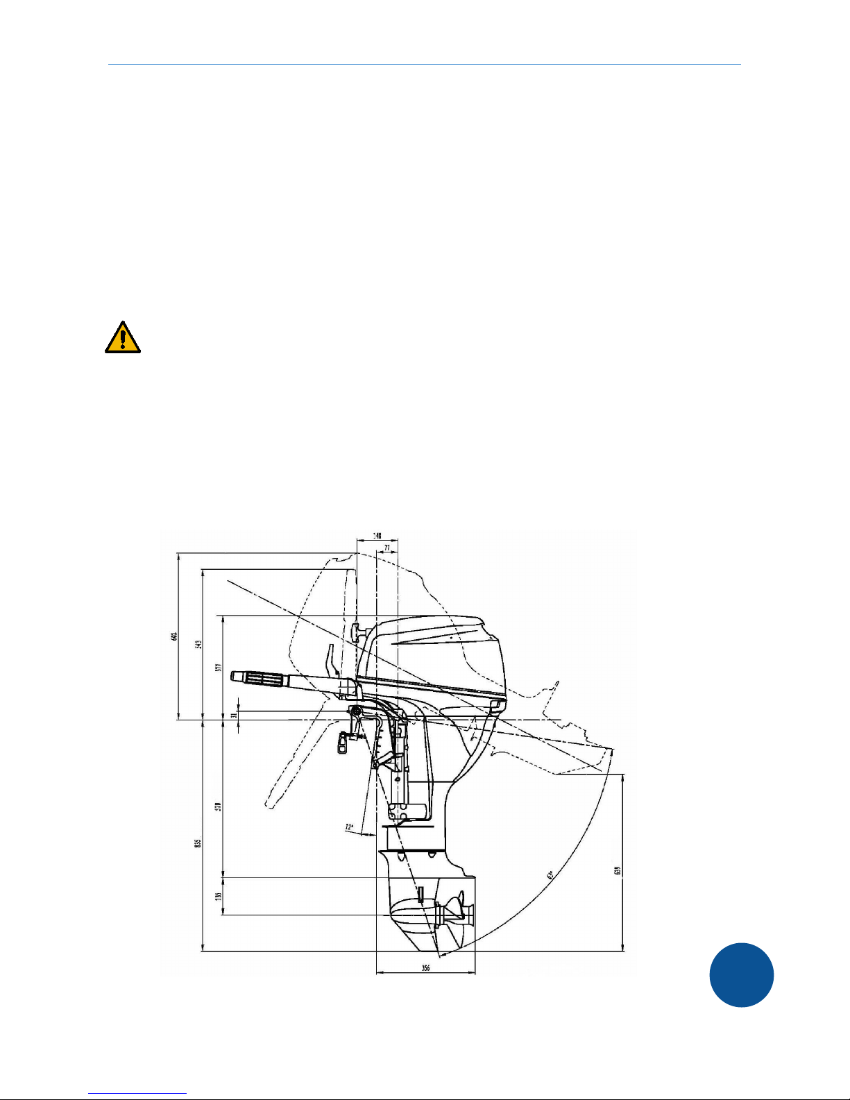
2.1 Installation to the transom
(Dimensions for AB13 AB22 - Thruster 1350 high)
Lift the motor always with suitable equipment and with two persons. Do not install the motor while
the boat is in the water unless fully secured.
If any problem shows with the correct installation, you need to contact an authorized specialist.
To fix the motor to the transom, tighten the clamp bolts. Never operate the motor just with the
clamp bolts. When correctly positioned, fix the motor with the 4 bolts to the transom.
antiventilation plate
specification plate
bolts
bolts
controller
electric motor
OPTION: power trim

aquawatt outboard motor operator’s manual
Version 1.22 EN | 31.03.2015 | copyright by aquawatt ™ | all4solar ™
9
INFORMATION
Secure the motor to the hull with a cable to the mounting bracket to prevent loss during installation
or de-installation process.
2.1 Electric power supply
CAUTION
The motor may only be connected to onboard power systems and accessories of 48/51 volts (13
KW engine) DC or 80 volts DC (22 KW engine) which comply with the CE / ISO standard.
Between the battery and the main switch a 300-400 Amp fuse (suitable for 50 or 80 volts DC ) has
to be connected.
cheaper alternative
All installations and insulations have to comply with 50 / 80 V DC low voltage and marine
electric installation regulations.
The main switch has to be rated for 50 / 80 volts DC / 300 Amp permanent charge.
A safety switch should be connected between the main switch and the battery.
A resistor should be connected to the main switch to enable the precharge of the motor
controller capacitors.
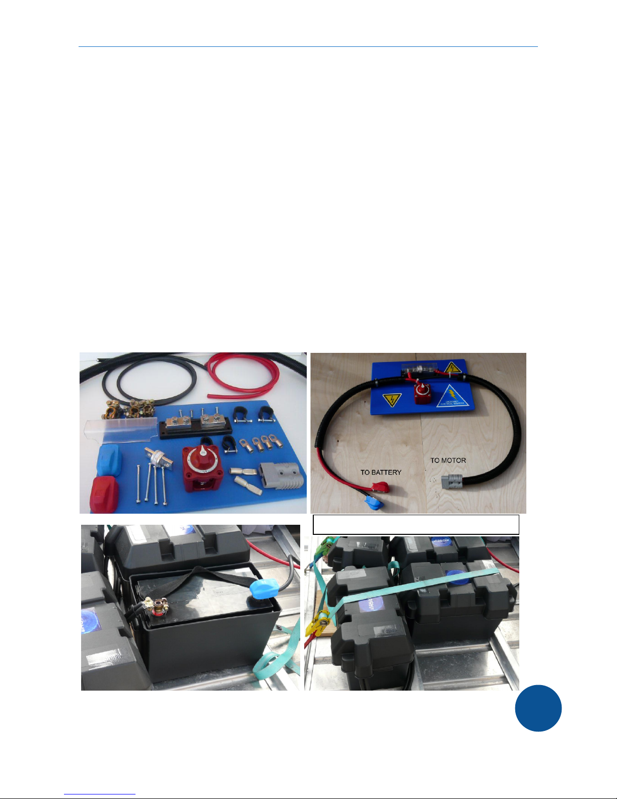
300 A main switch 48 V DC Non suitable battery switch Resistor
The cables should be as short as possible. 2 B&S tinned cables are to be used with an
adequate square size of 32.5 mm2 to 50 mm2 (for one motor only). For permanent full power
use of 300 Amps or longer distances 90/95 mm2 cables are recommended.
1 – Switch off main switch
2 – Switch off emergency switch
3 – Connect battery
4 – Connect engine
5 – Switch on emergency switch
Wait a few seconds
6 – Switch on main switch
7 – Switch on engine
Resistor to be
connected to both
terminals of the
switch. If
continuously
connected, this can
discharge the
battery. Disconnect
the battery with the
emergency switch.
This guide helps you to setup your electric boat propulsion
respecting the highest safety levels. You can connect the
engine directly to a battery at your own risk, but we strongly
recommend to use suitable fuses and switches.
aquawatt outboard motor operator’s manual
Version 1.22 EN | 31.03.2015 | copyright by aquawatt ™ | all4solar ™
10
The lugs and battery terminals need to be eligible for 300 Amp / 50 / 80 volts DC.
The operator has to have access to the emergency switch at all times!
The motor is supplied with a SB 175 or SB 350 plug. All connections have to be mounted at a
dry place under deck / covered against rain and sea water. The switch board should be made of
con conducting material (plastic or wooden board 10 – 15 mm).
The maximum battery idle voltage may not be higher than 60 volts DC (or 85 volts for 22 KW).
The maximum battery voltage under power is 54 / 80 volts DC. Die minimum battery voltage is
40 volts DC (59 V for 22 kw version). Variations to these voltages can cause severe damage to
the motor.
The onboard installation of the power supply should be supervised by an authorized specialist.
Operation is only allowed with a battery power supply. The direct supply from solar panels or
generators can damage the controller. If the battery is charged with a battery charger or solar
panels, the motor should be disconnected by the main switch unless suitable charge controllers
are used.
Only use battery chargers and cables, suitable for the use in the marine environment. The safe
installation and operation is not part of this manual.
Overview material needed for a simple switch board & battery connection
See aquawatt parts list and section 11 for more details
secure batteries and protect terminals
aquawatt outboard motor operator’s manual
Version 1.22 EN | 31.03.2015 | copyright by aquawatt ™ | all4solar ™
11
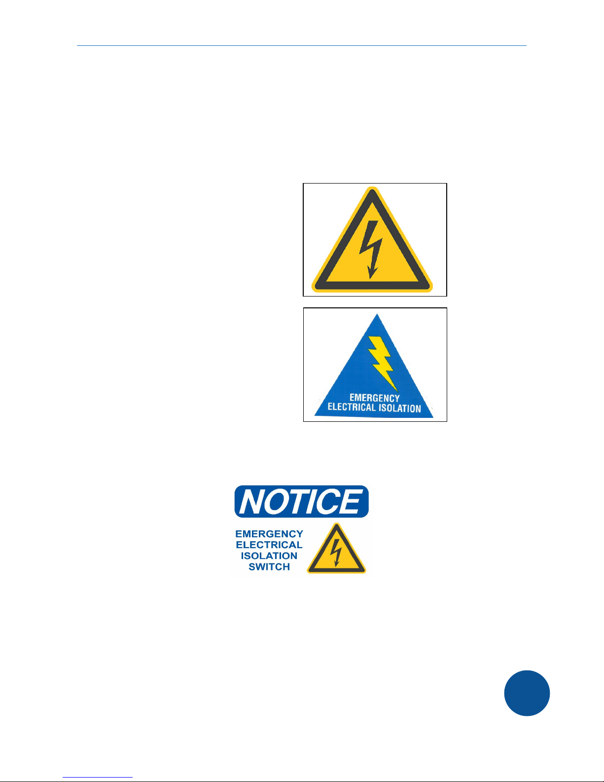
2.2 Safety stickers
The following safety stickers are recommended to be fixed to the system. The operator is
responsible for a safe installation, operation and proper indication of any dangerous parts.
High voltage sign (example only)
On motor hood
On battery box
On switch board
Emergency switch (example only)
On switch board
Aquawatt supplies two vinyl stickers with each motor kit (approx 18 x 25 cm)

aquawatt outboard motor operator’s manual
Version 1.22 EN | 31.03.2015 | copyright by aquawatt ™ | all4solar ™
12
2.3 Warranty information operation / installation
Incorrect installation, use of unsuitable accessories or variations in voltage voids the warranty.
Electrolysis is the decomposition of metals exposed to an electric current. When your boat is
connected to a shore power AC electrical system, it is also connected to an earth ground circuit.
This can cause an electrolytic current which causes the decomposition of all submerge metal. The
manufacturer’s warranty does not cover corrosion. Check and change anodes periodically.
WARNING – CAUTION – MOTOR OPERATION
Never operate the motor out of the water. Not even for a few seconds. When turning the key
switch, the electric motor turns at 600 revolutions per minute, even no gear is shifted. The electric
motor also operates the water pump to cool the engine. If the water intake below the antiventilation
plate is not in the water, the impeller of the pump will be destroyed within seconds. This can also
result in the damage to the seal of the gearbox.
To test your motor on land, the propeller needs to be dismantled and the water intake has to be put
in a water tank at least 10 cm under water level.
Alternatively for a short run to clean the water system from salt water, a outboard flusher can be
used. Sufficient water pressure has to be available. If water does not drain from water outlet after
starting the motor, there is no sufficient water pressure. Stop immediately!
DO NOT OPERATE
BEFORE YOU HAVE
READ THE ENTIRE
MANUAL
aquawatt outboard motor operator’s manual
Version 1.22 EN | 31.03.2015 | copyright by aquawatt ™ | all4solar ™
13
3) Installation of remote controlled motors
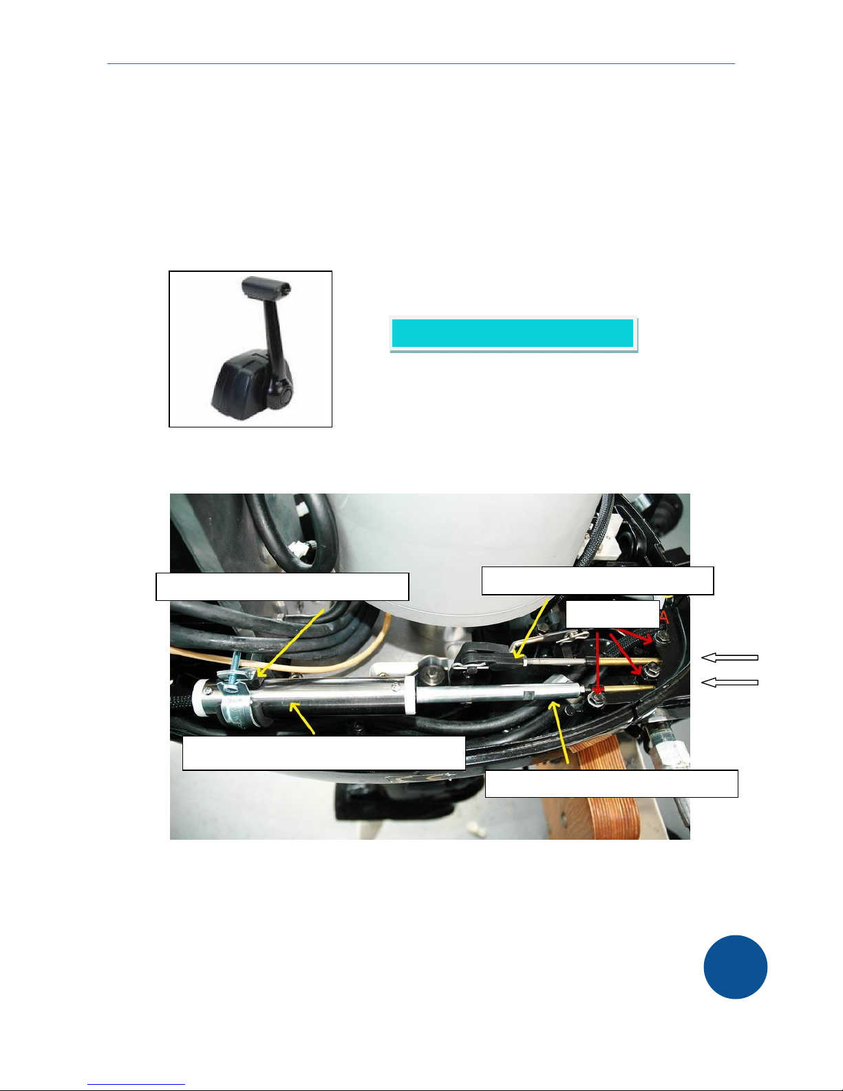
3.1) Throttle and gear shift
For throttle and gear shift operation a single lever power engine control needs to be installed on
the boat. Standard stainless steel throttle and gear shift cables to be used.
Side view to throttle and gear shift connection
To fix the controller cables, unlock the 3 bolts “A” to remove the cover.
The remote operated outboard motor is equipped with a electronic throttle position encoder and an
adapter for the gear shift cable. Both adapters are equipped with a 10 – 32 UNF standard thread.
The throttle and gear cable need to have a nut to secure the connection.
see aquawatt accessory list
Clamp to adjust throttle position encoder Gear shift connection adapter
Bolts A
Throttle position encoder
Throttle connection adapter
aquawatt outboard motor operator’s manual
Version 1.22 EN | 31.03.2015 | copyright by aquawatt ™ | all4solar ™
14
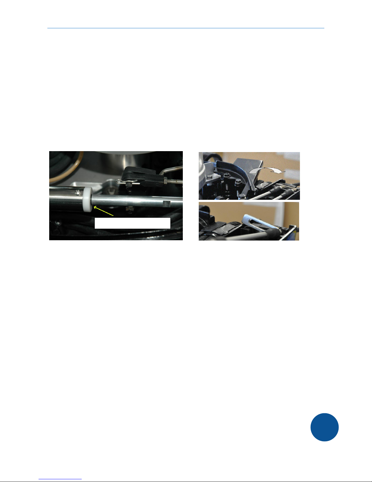
To fix the cable to the throttle position encoder, the connecting rod can be turned. The u-head of
the gear shaft can be removed to fix the cable.
The gear shift has to be adjusted that at the neutral position of the single lever, the u-head is in
neutral position too and the bolt can be easily inserted.
For fine adjustment the thread at the end of the cable can be turned and secured with the nut.
The throttle possition encoder has to be in the neutral position where marked when the single lever
is in neutral position (see picture). The throttle is activated when the rod is moved in the encoder
tube.
If this setting is not correct, the motor cannot be started. The fine adjustment can be done by
turning the thread of the cable or by moving the encoder by loosening the clamp.
The key switch, the boat kill switch and the multi functional display are supplied separately for the
remote controlled engine. These have to be mounted to the helm stand with the supplied cables.
(See 3.3)
Suitable cables and single lever power engine controls can be purchased from aquawatt or marine
supplier. Installation on the boat has to be done by an experienced person.
Installation and maintenance of lever and cables are not part of this manual. Please refer to the
supplier‘s instructions.
Neutral position marking

aquawatt outboard motor operator’s manual
Version 1.22 EN | 31.03.2015 | copyright by aquawatt ™ | all4solar ™
15
3.2) Steering
The motor needs to be equipped with a suitable, standardized and certified steering kit.
The steering equipment should comply with CE / EN 28848.
There are two methods for the installation of the steering.
Tilt tube mounting
The top end of the steering cable runs through the tilt tube of the motor. This method needs a
suitable steering link. This is the most common and recommended method.
Steering cable
Connection of steering link to motor
Steering link
aquawatt outboard motor operator’s manual
Version 1.22 EN | 31.03.2015 | copyright by aquawatt ™ | all4solar ™
16
Transom support mounting
Alternatively the steering cable can be fixed at the transom of the hull. This needs a special
support unit to hold the cable to the transom.
The installation and connection of the steering system should only be done by an experienced
specialist.
DANGER
Faulty installations of steering, gear and throttle can result in severe or deadly injuries.
External gear and steering systems have to be maintained according to the instructions of the
manufacturer. This is not part of this manual.

aquawatt outboard motor operator’s manual
Version 1.22 EN | 31.03.2015 | copyright by aquawatt ™ | all4solar ™
17
3.3) Display & switches
The wiring – kit is supplied with the 12R motor. If the cables are removed from the switches,
ensure that they are remounted exactly as supplied.
Install the display; the key switch and the emergency switch to a stable, non conducting surface
and make sure, the backside of the units are not exposed to water or humidity.
(Installation just for demonstration purposes)
Optional ampere hour meter recommended (use system capable to measure 60 V DC / 300 A or
90 V DC / 300 A). This is included in the lithium battery packs, if purchased from aquawatt.
The shunt included with the meter has to be installed between the negative battery pole and the
fuse / main switch. The battery charger has to be connected on the fuse side and not directly to the
negative battery pole, as otherwise the meter cannot count the amp hours charged.
See separate manual for battery installation and operation instructions.
aquawatt outboard motor operator’s manual
Version 1.22 EN | 31.03.2015 | copyright by aquawatt ™ | all4solar ™
18
4) Operational area
The aquawatt motor can be used in fresh water and if equiped with suitable anodes in salt water. If
used in salt water, it has to be assured, that no salt water runs under the cover. The anode has to
be cleaned a replaced if 25% is corroded.
After the use in salt water, we recommend to flush the cooling system (see section 2.2 for details).
Never run the motor with removed hood!
If the boat is moored, the motor should always be lifted out of the water and set in the direction
where wind and waves head to.
ATTENTION
The motor should only be used in clear water which is not colder than 10 degrees Celsius and not
warmer than 30 degrees Celsius. Variations of these limits can result in damage of the motor and
the cooling system.
5) Drive with the aquawatt outboard motor
DANGER
As boat operator you are fully responsible for the security of all passengers on board as well as to
any other water craft, swimmers or animals within your area of operation.
You have to be aware of all rules & regulations for operating a water craft. The detailed knowledge
of this operator’s manual and the instructions for the boat and all equipment is a very important
part of your responsibility.
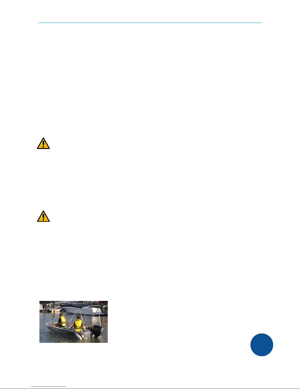
A swimming person cannot avoid very quickly even if a boat runs at low speed. Therefore you have
to switch off the motor if a person is close to your boat.
ANY CONTACT WITH A MOVING VESSEL, THE PROPELLER OR ANY OTHER PART OF THE
MOTOR OR THE BOAT CAN LEAD TO SEVERE INJURY.
Always equip your boat with safety gear
aquawatt outboard motor operator’s manual
Version 1.22 EN | 31.03.2015 | copyright by aquawatt ™ | all4solar ™
19
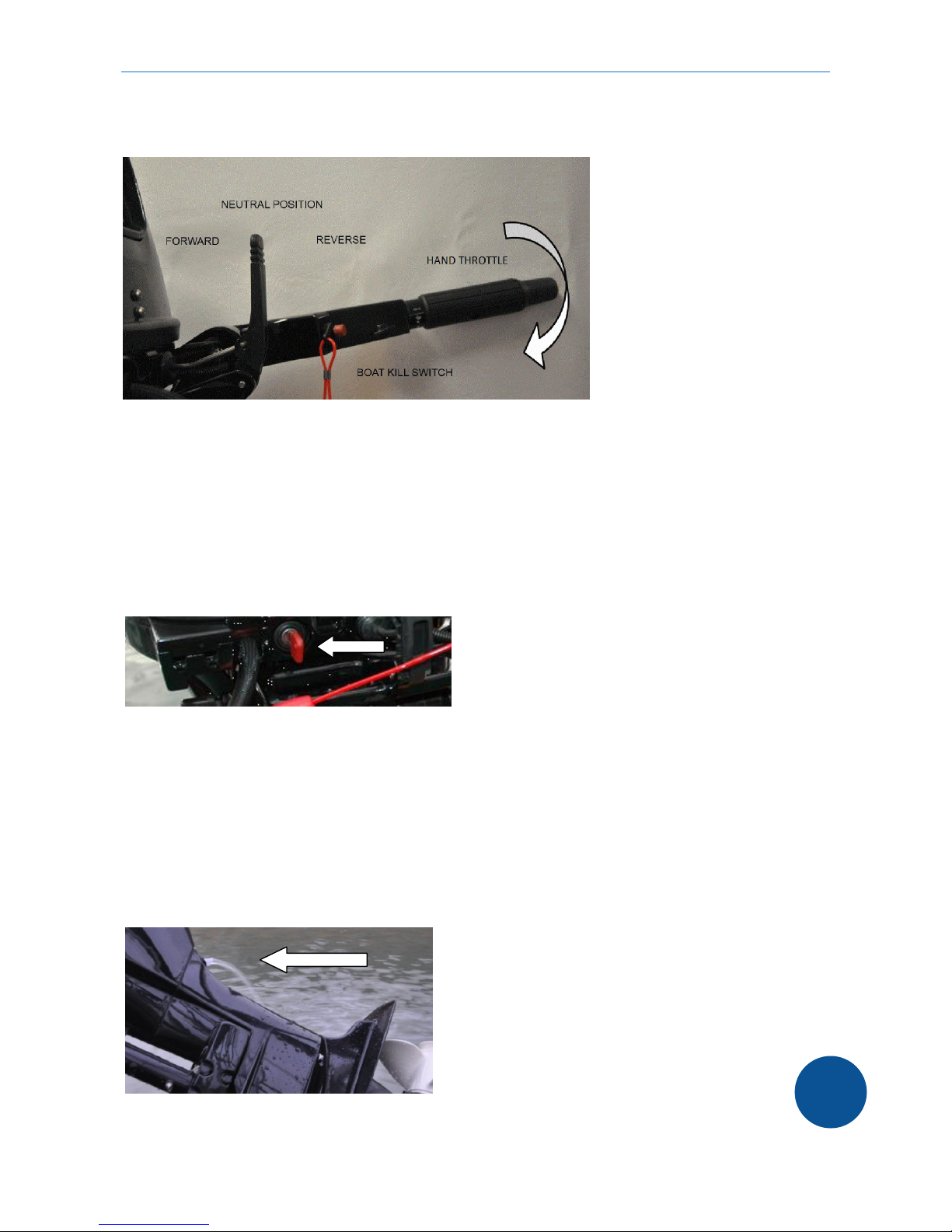
5.1) Turn-on procedure
Turn-on the battery main switch
Connect boat kill key to the switch (see 2.1.)
Turn tiller handle to the slow position or shift the engine control to the neutral position
Move the gear switch to neutral position or the engine control lever to neutral position
Switch the key to the ON position
The motor starts operating at 600 turns per minute to ensure the water flow through the cooling
system.
The motor will not start, if a gear is shifted, the throttle is not in lowest or neutral position or the
boat kill switch is off. If no gear is switched, the motor power cannot be increased!
If the motor runs after approximately 10 seconds cooling water has to run out of the water exit. This
has to be checked on regular bases, as without water flow, the motor and the controller will be
damaged due to overheating!

aquawatt outboard motor operator’s manual
Version 1.22 EN | 31.03.2015 | copyright by aquawatt ™ | all4solar ™
20
5.2) Drive forward
Turn the hand throttle to minimum speed or the engine control to the neutral position.
Switch the gear to forward (in the forward direction) or move the engine control to forward.
The boat starts to move slowly even the hand throttle has not been turned.
To accelerate turn the hands throttle or move the engine control slowly.
We recommend to not operate the engine at full power (300 Amps on display) for more than 20
minutes depending on the batteries and cables used for installation. If you need full power all the
time, 2 x 32.5 mm2 cables should be used for all connections from the controller to the batteries.
5.3) Reverse
The same procedure as driving forward, but move the gear switch backwards or the power engine
control backwards. Do not drive backwards at high speeds!
When changing from the forward to the reverse gear always stop at the neutral position for two
seconds. ONLY SWITCH GEARS WHEN THROTTLE IS IN IDLE / NEUTRAL POSITION.
CAUTION
Changing gears at high speeds can cause heavy damage or injury!
5.4) Safety Switch
If the lanyard is pulled from the kill switch the motor stops immediately.
The line should be fixed to the operator in case of loss of control or
passengers go overboard.
The use of the lanyard system is recommended but we need to
highlight the risk of a sudden motor stop.
CAUTION
An accidental activation of the boat kill switch can cause loss of control and injury to the
passengers!
5.5) Multi functional display
If only the yellow light flashes, this shows a normal operation.
The display indicates the most important information. Besides the selected information, the battery
charge status is always shown on the top of the screen between 0 (empty) and 1 (full).
When turning the key switch, the system shows the motor rotation speed per minute.
To change to another reading, push the button to the right. To move back, push the left button.
This manual suits for next models
3
Table of contents


