Aquion aspen 48m User manual

Aquion Energy, Inc.
32 39th Street
Pittsburgh, PA 15201
+1 412.904.6400
aquionenergy.com AQ-OP-00018_E.01 | 02.23.17
Aspen Battery
Installation & Operation Manual
Aspen 48M
Aspen 48S
Aspen 24S

AQ-OP-00018_E.01 | 02.23.17
© 2017 Aquion Energy, Inc.
The information in this document is subject to periodic updates and changes. Upon any updates or
changes to the above-described material, Aquion Energy will provide new drawings and/or associated
documentation that will supersede those contained in this document. Contents are subject to change
without notice.
Find all product documentation at http://aquionenergy.com/support/product-documentation.
Symbols in This Document
WARNING
WARNING
indicates a hazardous situation that, if not avoided,
could result in death, injury, or damage.
ATTENTION
ATTENTION
indicates information that is important but not
critical to safety.

i AQ-OP-00018_E.01 | 02.23.17
Table of Contents
1Introduction____________________________________________________________________ 1
1.1 About This Manual 1
1.2 Contact Information 1
2Product Information _____________________________________________________________ 1
2.1 Product Overview 1
2.2 Product Specification 1
2.3 UL 2
2.4 CE 2
2.5 Cradle to Cradle Certification 2
2.6 Electromagnetic Compatibility –48M 2
2.6.1 FCC 2
2.6.2 CE 2
3Safety Information ______________________________________________________________ 3
3.1 Electrical Hazards 3
3.2 Electrical Safety 3
3.3 Chemical Hazards 3
3.4 Gas Emissions 3
3.5 Weight Hazards 4
3.6 Ingress Protection 4
3.7 Decommissioning Hazards 4
4Transportation and Receipt of Product _____________________________________________ 5
4.1 Packaging 5
4.2 Shipping 5
4.2.1 Hazards 5
4.2.2 Requirements 5
4.3 Delivery Inspection 5
4.4 Disassembly Hazards 6
5Installation _____________________________________________________________________ 7
5.1 Unpacking 7
5.2 Site Requirements 7
5.2.1 Exposure and Enclosure 7
5.2.2 Size and Weight 7
5.2.3 Ventilation 7
5.2.4 Humidity 8
5.2.5 Ambient Temperature 8
5.3 Moving 8
5.3.1 48S, 24S 8
5.3.2 48M 8
5.4 Placement 9
5.5 Fuse Connection Instructions – 48M 9
6Electrical Integration____________________________________________________________ 12
6.1 Electrical Interfaces and Connections 12
6.1.1 48S, 24S 12
6.1.2 48M 13
6.1.3 Contactor Control – 48M 16
6.2 Product Wiring Diagrams 16

ii AQ-OP-00018_E.01 | 02.23.17
6.3 Racking/Scaling Systems 18
6.4 Cabling Requirements 18
6.5 Parallel Wiring 18
6.5.1 48S, 24S 18
6.5.2 48M 18
6.5.3 Monitoring 19
6.5.4 Overcurrent Protection 20
6.5.5 Grounding 20
6.6 Series Wiring 20
7Commissioning ________________________________________________________________ 21
7.1 Initial Charge 21
7.2 Voltage Matching 21
7.3 Configuring Inverters and Charge Controllers 21
8Operation_____________________________________________________________________ 22
8.1 Operational Limits 22
8.2 Charge Profiles 22
8.2.1 Recommended Charge Profile 22
8.2.2 Boost Charge Profile 23
8.2.3 Three-Stage Charge Profile 24
8.3 State of Charge 25
8.3.1 Partial State of Charge 25
8.3.2 Determining State of Charge 25
8.4 Capacity and Ambient Temperature 25
8.5 Self-Discharge 26
8.6 Long-Term Storage 26
8.7 Recycling and Disposal 26
8.8 Record Keeping 26
9Warranty _____________________________________________________________________ 27
10 Technical Support ______________________________________________________________ 27
11 Further Reading________________________________________________________________ 27

1 AQ-OP-00018_E.01 | 02.23.17
1Introduction
1.1 About This Manual
This manual is intended to provide technical information and safe practices regarding receiving,
installing, and operating the Aquion Energy Aspen battery. For complete safety information, refer to
the Safety Data Sheet (SDS) included with your product shipment.
WARNING
Failure to follow the instructions in this document could result in fire, electric shock, and/or
other injury or damage.
1.2 Contact Information
Mail: Aquion Energy
32 39th Street
Pittsburgh, PA 15201
Telephone: +1 412.904.6400
Web:
aquionenergy.com
2Product Information
2.1 Product Overview
Aqueous Hybrid Ion (AHITM) batteries use non-toxic, non-corrosive materials to make the world’s only
clean and sustainable electrochemical storage solution. Aquion Aspen 48S, 48M, and 24S batteries
provide long-duration, stationary storage for residential solar, off-grid, microgrid, and energy
management applications.
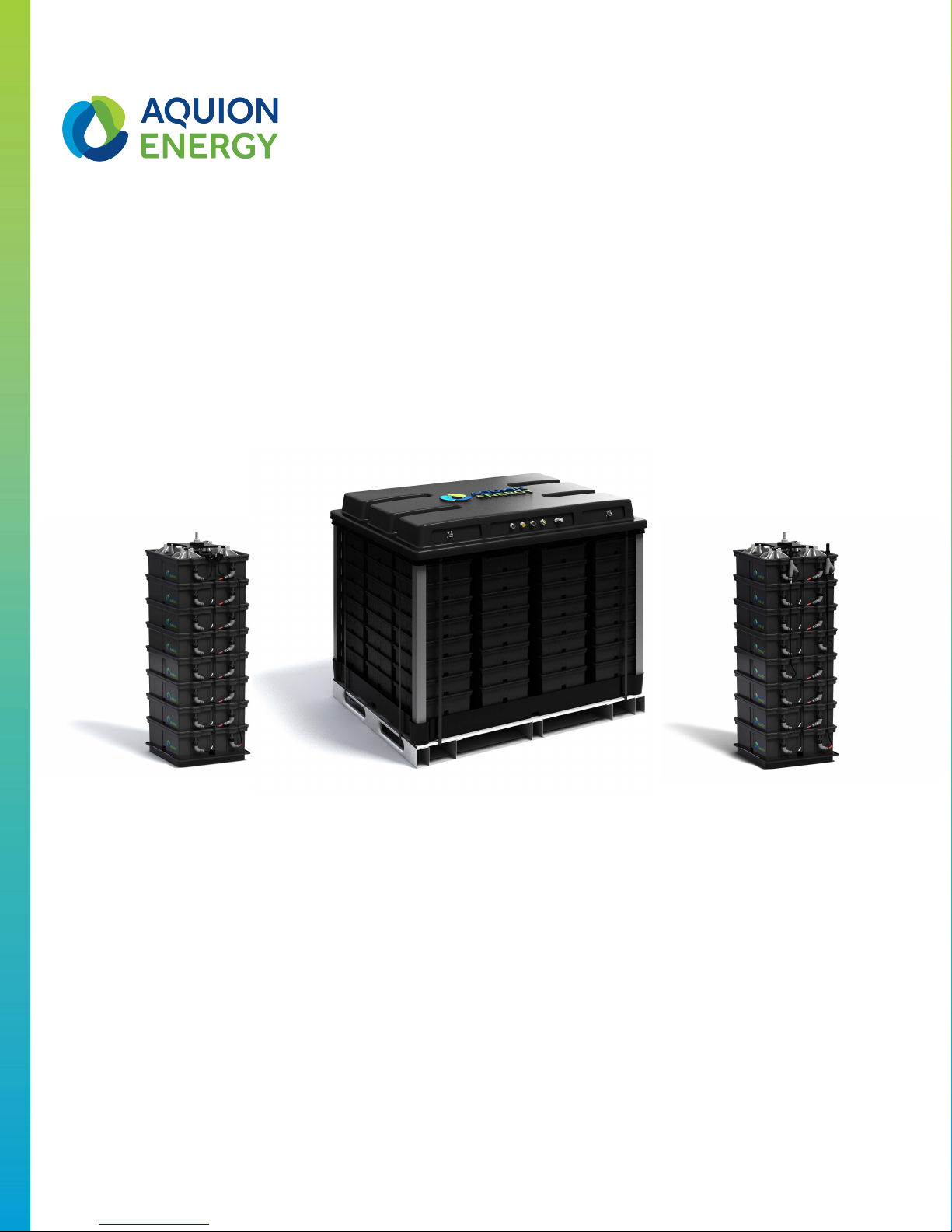
Aspen 48S
The Aspen 48S is the base component of Aquion Energy’s scalable energy solutions. The Aspen 48S
connects eight AHI battery cells in series for an unfused, 48 V product.
Aspen 48M
The Aspen 48M is a palletized, pre-wired, plug-and-play battery bank. It can serve as a stand-alone
system or as a modular building block for larger systems. The Aspen 48M battery connects twelve
Aspen 48S batteries in parallel, adds fusing for each 48S, and includes on-board sensing of the 48M’s
voltage, current, and temperature.
Aspen 24S
The Aspen 24S is a 24 V variant of the Aspen 48S battery. The Aspen 24S connects two parallel strings
of four series-connected AHI battery cells for an unfused, 24 V product.
2.2 Product Specification
Voltage curves, operational efficiency, capacity by charge and discharge currents, standards
compliance and certification status, and more information can be found on the Product Specification
Sheet for your battery model (http://aquionenergy.com/support/product-documentation). The
battery’s model number appears on the product label.

2 AQ-OP-00018_E.01 | 02.23.17
2.3 UL
The Aspen 48S and 24S are UL recognized. The following certification tests have been completed:
+
UL 1973-13 Overcharge
+
UL 1973-14 Short Circuit
+
UL 1973-15 Overdischarge Protection
+
UL 1973-16 Temp and Ops
+
UL 1973-17 Imbalanced Charging
+
UL 1973-23 Vibration
+
UL 1973-24 Shock
+
UL 1973-25 Crush
+
UL 1973-26 Static Force
+
UL 1973-27 Impact
+
UL 1973-30 Mold Stress
+
UL 1973-31 Pressure Release
+
UL 1973-32 Start-To-Discharge
+
UL 1973-34 Resistance to Moisture
+
UL 1973-35 Salt Fog
+
UL 1973-36 External Fire Exposure
2.4 CE
The Aspen 48S, 48M, and 24S batteries are CE marked. They have been assessed to meet high safety,
health, and environmental protection requirements for sale in the Single Market in the European
Economic Area. Contact Aquion for any of the Aspen batteries’ CE Declaration of Conformity.
2.5 Cradle to Cradle Certification
The Aspen 48S and 24S batteries are Cradle to Cradle CertifiedTM Bronze products. Cradle to Cradle
CertifiedTM is a certification mark licensed by the Cradle to Cradle Products Innovation Institute, which
independently assesses and certifies products for material health, material reutilization, renewable
energy use and carbon management, water stewardship, and social fairness.
2.6 Electromagnetic Compatibility – 48M
2.6.1 FCC
This device complies with part 15 of the FCC Rules. Operation is subject to the following two
conditions: (1) This device may not cause harmful interference, and (2) this device must accept any
interference received, including interference that may cause undesired operation.
Note: This equipment has been tested and found to comply with the limits for a Class A digital device,
pursuant to part 15 of the FCC Rules. These limits are designed to provide reasonable protection
against harmful interference when the equipment is operated in a commercial environment. This
equipment generates, uses, and can radiate radio frequency energy and, if not installed and used in
accordance with the instruction manual, may cause harmful interference to radio communications.
Operation of this equipment in a residential area is likely to cause harmful interference, in which case
the user will be required to correct the interference at his own expense.
2.6.2 CE
This product may cause interference if used in residential areas. Such use must be avoided unless the
user takes special measures to reduce electromagnetic emissions to prevent interference to the
reception of radio and television broadcasts.

3 AQ-OP-00018_E.01 | 02.23.17
3Safety Information
Only qualified individuals are to install and service battery systems.
3.1 Electrical Hazards
Never place foreign objects or tools in or on the unit. The metal parts of the battery terminals are
always live. Electrical hazards exist in the voltage and current ranges that are found in battery systems
and associated electronics.
WARNING
Connecting Aspen batteries in series can lead to dangerously high voltages. Aquion must review
any series configurations of Aspen 48S or 48M batteries prior to installation. Never connect
Aspen 24S batteries in series. When connecting Aspen 48S or 24S batteries in parallel, Aquion
recommends placing overcurrent protection devices as close as possible to the DC bus.
3.2 Electrical Safety
The batteries must be protected from overcurrent charge and discharge with appropriately rated
overcurrent protection devices. If grounding is required, see Section 6.5.5.
Battery Model
Max.
Recommended
Charge/Discharge Current
Integrated Fusing
Notes
48S
20 A
None
48M
240 A
Twelve 1,000 V, 20 A fuses, one
per component 48S
battery
F
uses are disconnected at the
factory and will need to be connected
(see Section
5.5).
24S
3
0 A
None
3.3 Chemical Hazards
Aspen battery materials are non-toxic and present no chemical hazards. The AHI electrolyte is
sodium-sulfate-based saltwater with a neutral pH. In the unlikely event that the electrolyte comes in
contact with eyes or skin, thoroughly wash it out with water. Electrolyte residue on the battery terminal
can be wiped away with a cloth. A collection pan under the battery stack or module is not needed as
the electrolyte will not leak during normal operation, and any leaked electrolyte will not damage battery
surfaces or equipment. Refer to the Safety Data Sheet (SDS) for more information.
3.4 Gas Emissions
The battery may emit trace amounts of gas H2, O2, CO2, and CO during normal operation. These gases
do not accumulate in hazardous quantities in typical installations when the batteries are installed and
operated in accordance with the guidelines of this document (see Section 5.2.3). The battery has fully
passed UL 1973 overcharge testing, an abuse test that includes monitoring for combustible vapor
concentrations. Overcharging the battery (outside of specified guidelines) will result in venting of
some incremental amounts of the gases listed above through the pressure relief valve.

4 AQ-OP-00018_E.01 | 02.23.17
3.5 Weight Hazards
Aspen batteries must be transported and handled with appropriate precautions. See Section 5.3 for
moving and tilting restrictions.
Battery Model
Weight
Notes
48S
,
24S
118 kg (260 lbs)
48M
1,504 kg (3,315 lbs)
F
orklift trucks or pallet jacks are recommended for moving and positioning 48M
batteries
.
3.6 Ingress Protection
The International Electrotechnical Commission publishes the International Protection (IP) Code, which
classifies the degrees of protection provided by electrical equipment enclosures against ingress of
solid particles and liquid.
Battery Model
Solid Particle Protection Level 2
*
Liquid Ingress Protection Level 2
†
IP code
48S
,
24S
Confirmed
Confirmed
IP22
48M
Confirmed
Not tested
IP2X
*
Protected from ingress of objects greater than 12.5 mm, such as fingers or similar objects (IP
#
#).
†
Protected against harmful effects of ingress of dripping water when tilted up to 15 degrees, for a duration of 10 minutes or less (IP#
#
).
3.7 Decommissioning Hazards
AHI batteries are non-toxic and non-corrosive. Do not dump into any sewers, on the ground, or into
any body of water where water runs off into open bodies of water. Dispose of according to all federal,
state, and local regulations.

5 AQ-OP-00018_E.01 | 02.23.17
4Transportation and Receipt of Product
4.1 Packaging
Battery Model
Quantity
per Pallet
Packing Type
Tip
-N-Tell and Drop-N-Tell
Indicator Location
48S
,
24S
12 or fewer
Wrapped (U.S. shipments) or crated (outside
U.S.)
Affixed to outside of packaging
48M
1
Wrapped (all shipments)
Affixed to outside of wrapping
4.2 Shipping
Battery Model
Shipping Configuration Testing
State of Charge (SOC) and Voltage at Shipping
48S
Modified ISTA
*3H shipping test
<2% SOC, <45 V
48M
Pending modified ISTA 3H shipping test
<2% SOC, <45 V
24S
Modified ISTA
*3H shipping test
<2% SOC, <22.5 V
*
International Safe Transit Association
4.2.1 Hazards
Aquion batteries are not hazardous and are not regulated as dangerous goods by the U.S.
Department of Transportation (DOT). They do not need special transportation services. Customers
shipping Aquion batteries Ex Works (EXW) should request the most recent Safety Data Sheet (SDS)
from Aquion. Aquion includes a hard copy of the most recent SDS with every shipment.
4.2.2 Requirements
Aspen batteries should be shipped in an upright position and should not be tipped for extended
periods. Communicate this restriction to the shipper prior to transport. The affixed Tip-N-Tell
indicators trip if the package experiences extreme tilt. See Section 5.3 for moving and tilting
restrictions.
4.3 Delivery Inspection
Immediately upon delivery, inspect all hard goods for signs of damage or tipping during transit before
signing for the delivery. Any of the following may indicate damage during transport:
+Damaged or torn packaging
+Tripped Drop-N-Tell indicator
+Scraped or punctured product components
+Tripped Tip-N-Tell indicator
+Leaking electrolyte (clear liquid)
If you find damage, document any signs of damage on the bill of lading before accepting the shipment.
Separately document and photograph all damage, and make a claim with the carrier as soon as
possible. Contact your distributor immediately.
Slight bulges or depressions in the cases of Aspen 24S or 48S batteries are normal. The battery cases
are intentionally flexible to accommodate compression of the electrode stack and normal variations in
internal pressure during operation. A depression or bulge of up to 10 mm in the sidewall of the battery
case is not unusual, especially in new batteries, and does not present an unsafe condition. If a bulge
projects more than 10 mm, do not place the battery in service, or remove it from service if already
commissioned, and contact Aquion Technical Support (see Section 10).

6 AQ-OP-00018_E.01 | 02.23.17
4.4 Disassembly Hazards
WARNING
Do NOT attempt to disassemble Aspen 48S or 24S batteries. Do NOT remove the nut on the
compression fixture on top of the battery.
Aspen 48S and 24S batteries have been compressed to optimize performance. Releasing this load
could result in poor battery performance, permanent damage to battery components, and/or injury.

7 AQ-OP-00018_E.01 | 02.23.17
5Installation
ATTENTION
Aspen batteries ship at low state of charge and low voltage. See Section 7.1.
Aspen 48M fuses are installed but not connected. The battery will not function until the fuses
are connected. See Section 5.5.
Aspen 48M batteries and systems of sensed Aspen 48S batteries must be set up with the Aquion
Battery Monitoring System (BMS-200) before operation. See Section 5.4.
Installation of Aspen batteries requires accessories not supplied by Aquion. Find the complete
list of required accessories at http://aquionenergy.com/support/product-documentation.
5.1 Unpacking
Unpack all items carefully and note quantities received. Contact your authorized Aquion distributor if
any items are missing or damaged.
Battery Model
Shipping Pallet
Included
Accessories
48S
,
24S
Removable
Lifting eye
(one per pallet)
48M
Permanent
Amphenol DeviceNet Thick Patch Cable, 2 m, 90
°(one per 48M battery, may ship separately)
5.2 Site Requirements
5.2.1 Exposure and Enclosure
Aspen batteries should be installed indoors or enclosed from the elements. A fully sealed enclosure is
not recommended.
Install and operate Aspen batteries out of direct exposure to sunlight. Prolonged exposure to
ultraviolet light may damage the polypropylene casing and reduce product lifetime.
5.2.2 Size and Weight
Position Aspen batteries only on surfaces appropriately rated for the product’s weight. Ensure that the
installation location is large enough to contain the battery product.
Battery Model
Height
Width
Depth
Weight
48S
,
24S
935 mm (36.8”)
330 mm (13.0”)
310 mm (12.2”)
118 kg (260 lbs)
48M
1,159 mm (45.6”)
1,321 mm (52.0”)
1,016 mm (40.0”)
1,504 kg (3,315 lbs)
5.2.3 Ventilation
Aquion batteries emit trace amounts of gas during normal cycle operation. Aquion recommends
installing the Aspen 48S in a non-sealed, ventilated area:
+For installations in locations that are frequently occupied (more than 8 hours of human occupation
per 24 hours), Aquion recommends continuous ventilation of 0.85 m3/hr (0.5 ft3/min) per
operational battery stack.
+For installations in locations that are infrequently occupied (less than 8 hours of human occupation
per 24 hours), Aquion recommends CO detection and periodic ventilation of 0.85 m3/hr (0.5 ft3/min)

8 AQ-OP-00018_E.01 | 02.23.17
per operational battery stack or in any instance when the measured CO concentration is greater
than the user’s defined environmental health and safety guidelines for CO.
Alternatively, in North America, IBC and/or NFPA 1 guidelines recommend that all battery installations
in enclosed spaces include ventilation equal to either six (6) air changes per hour or ventilation at
1 ft3/min per square foot of room size. In Europe and other locations, EN 50272 guidelines
recommend that batteries be installed in well-ventilated rooms where ventilation corresponds to
battery capacity and the exhaust air is discharged outside the building.
5.2.4 Humidity
Install Aspen batteries in clean, ordinary conditions protected from water exposure. Direct exposure
of Aspen batteries to water may cause shorting. The batteries may be installed in humid or coastal
regions with atmospheric salt.
5.2.5 Ambient Temperature
Aspen batteries must be operated in temperatures between -5°C and 40°C on a 24-hour average.
Operation above or below these limits will cause advanced degradation of the battery chemistry.
Aspen batteries must be stored in temperatures between -10°C and 40°C. Storage above or below
these limits may permanently damage the batteries.
5.3 Moving
5.3.1 48S, 24S
Use proper lifting procedures and personal protective equipment when moving Aspen batteries. The
Aspen 48S and 24S batteries have been designed to be moved using a lifting eye, included on each
pallet of batteries, screwed onto the threaded, metal tie-rod that runs vertically through the center of
the battery. No other component of the Aspen 48S and 24S is designed to support the battery’s
suspended weight. Use a crane, hoist, or similar device of appropriate load-bearing capacity to lift one
Aspen 48S or 24S battery at a time by the lifting eye.
NEVER LIFT ASPEN 48S OR 24S PRODUCTS BY THE TERMINALS OR ANY PART OTHER THAN AN
APPROPRIATELY RATED LIFTING EYE THREADED ONTO THE TIE-ROD AS THIS WILL VOID THE
WARRANTY AND MAY CAUSE DAMAGE TO THE PRODUCT AND/OR SIGNIFICANT INJURY.
Alternatively, use an appropriately sized hand truck to move Aspen 48S or
24S batteries. Position the battery on the hand truck so that the wiring faces
out, away from the upright frame of the hand truck. During movement to
the installation site and during installation, batteries may be tilted up to
forty-five (45) degrees for up to one hour. Before moving any Aspen 48S or
24S batteries, ensure that the travel path will not require tipping the battery
more than forty-five (45) degrees and that the installation location is level.
5.3.2 48M
The Aspen 48M battery must be transported and handled with appropriate precaution. The use of
forklift trucks and pallet jacks is recommended to move and position the battery. Before moving any
Aspen 48M battery, ensure that the travel path will not require tipping the battery more than fifteen
(15) degrees and that the installation location is level.

9 AQ-OP-00018_E.01 | 02.23.17
5.4 Placement
ATTENTION
Before restricting physical access to 48M or sensed 48S battery systems, such as in racking or
shipping containers,
1. Connect Aspen 48M fuses. This requires removing and replacing the top cover. See
Section 5.5.
2. Set up the batteries with the Aquion BMS-200. This requires physical connection of power
and communication cables. See the BMS-200 Installation & Operation Manual for
instructions.
Aspen batteries do not need any particular amount of clearance between other Aspen batteries or
other architectural features, so they can be arranged in tightly packed groups. Always follow local
codes for aisle and access requirements. Access and working spaces shall comply with all local codes.
However, when interpreting codes, note the following points:
+Access to the battery stack connections and lifting point for wiring and installation into the energy
storage system is available at the top of the batteries.
+When wired in parallel, Aspen batteries operate below 60 Vdc. Normal installation and operation of
Aspen batteries do not require access to the sides of the batteries, including the side with cable
harnesses.
+Aquion batteries do not normally require examination, adjustment, servicing, or maintenance while
energized.
Do not stack Aspen batteries on top of each other. Do not place other items on top of the batteries.
Aspen batteries are designed to be installed in an upright position (less than fifteen (15) degrees of tilt).
5.5 Fuse Connection Instructions – 48M
Each Aspen 48M battery ships with 12 installed, but disconnected, 20 A fuses, one for each
component Aspen 48S, located beneath the battery’s top cover. All 12 fuses must be connected for
the battery to operate. Connect the fuses before installing the battery in your system.
1. Remove the battery’s top cover.
a. Remove the four bolts from the front and
back of the battery’s top cover.

10 AQ-OP-00018_E.01 | 02.23.17
b. Lift off the cover by raising the back end
first, sliding the cover slightly forward to
clear the terminal posts, and lifting the
entire cover clear.
2. Connect the two fuse bundle connectors.
a. Inside the top tray, locate the fuse board
and the two loose fuse bundle connectors.
b. Insert the J1 and J2 connector bundles into
the J1 and J2 receptacles, respectively, on
the fuse board until you hear a click. Check
that the connectors are tightly secured.
3. Replace the top cover.
a. Lower the front end over the terminal
posts, and then lower the back end.

11 AQ-OP-00018_E.01 | 02.23.17
4. Replace the four bolts on the front and back
of the top cover. For each bolt:
a. If the clip beneath the edge of the cover has
tilted, realign the clip vertically so that its
hole aligns with the hole in the cover.
b. Screw in the bolt through the hole in the top
cover and the hole in the clip.

12 AQ-OP-00018_E.01 | 02.23.17
6Electrical Integration
6.1 Electrical Interfaces and Connections
6.1.1 48S, 24S
Aspen 48S and 24S battery terminals are standard MC4-type solar connectors (48S battery pictured
below). Aquion does not supply mating connectors. For optimal battery performance, Aquion
recommends non-gold-plated, MC4-compatible solar connectors, such as the Amphenol H4, Flagsun
FC-001, or equivalent. Find details on the battery terminal parts and the complete list of required
accessories at http://aquionenergy.com/support/product-documentation.

13 AQ-OP-00018_E.01 | 02.23.17
6.1.2 48M
Aspen 48M installation requires mating connectors and cables. Aquion supplies one (1) DeviceNet
communications cable per 48M battery. Aquion does not supply the other accessories. Find the
complete list of accessories at http://aquionenergy.com/support/product-documentation.
①Negative (-) Battery Terminal
Function: Negative termination of battery
Part:
Amphenol RADLOK RL9-100-101 Black
Mating connector:
Amphenol RADLOK Tubular Connector Black
RL0-100-1-xxBK
*
or equivalent. Part not supplied by Aquion.
Pin # Name Wire Color Description
1 BATT- Black Battery Negative Terminal
②Positive (+) Battery Terminal
Function: Positive termination of battery
Part:
Amphenol RADLOK RL9-100-101 Red
Mating connector:
Amphenol RADLOK Tubular Connector Red
RL0-100-1-xxRE
*
or equivalent. Part not supplied by Aquion.
Pin # Name Wire Color Description
1 BATT+ Red Battery Positive Terminal
*“xx” is cable size, which is determined by your installation.

14 AQ-OP-00018_E.01 | 02.23.17
③24V I/O In
Function: Power input for contactor control
Part:
Amphenol SineCo MN41PW02M005 4-pin miniBOSS, Male
Receptacle, External Threads
Mating connector:
Amphenol SineCo MN47[A/B]4[A/B]C01Mxxx*4-pin
miniBOSS Cordset, or equivalent, connected to a 24 V power supply (not
shown; see Section 6.1.3). Parts not supplied by Aquion.
Pin # Name Wire Color Description
1 24V_IO_NEG Black 24 V I/O Negative
2 24V_IO_POS White 24 V I/O Positive (for driving contactors)
3 INTLK_RLY_IN Red Interlock Relay In (normally open)
4 RLY_RTN_IN Green Interlock Relay Return In
④24V I/O Out
Function:
Power output for contactor control
Part:
Amphenol SineCo MN44PW02M030 4-pin miniBOSS, Female
Receptacle, Internal Threads
Mating connector:
Amphenol SineCo MN47[A/B]4[A/B]C01Mxxx*4-pin
miniBOSS Cordset or equivalent. Part not supplied by Aquion.
Pin # Name Wire Color Description
1 24V_IO_NEG Black 24 V I/O Negative
2 24V_IO_POS White 24 V I/O Positive (for driving contactors)
3 INTLK_RLY_IN Red Interlock Relay In (normally open)
4 RLY_RTN_IN Green Interlock Relay Return In
*“[A/B]” is connector style: Afor straight, Bfor right-angle. The first “[A/B]” refers to the female connector, the second, the male. Choose the
appropriate connector style for your installation. “xxx” refers to cable length, which is determined by your installation’s requirements.

15 AQ-OP-00018_E.01 | 02.23.17
⑤CAN In
Function: Input for sensing board power and CANbus communication
Part:
Amphenol SineCo DeviceNet MN51PD01M005 Male Receptacle,
External Threads
Mating connector:
Amphenol SineCo DeviceNet Thick
MN57[A/B]4[A/B]D01Mxxx*Patch Cable or equivalent. Aquion supplies one
(1) 2-m, 90
°
-connector patch cable per 48M battery.
Pin # Name Wire Color Description
1 CAN_GND Bare Isolated CAN Ground
2 24V_LOGIC_POS Red 24 V Logic Positive
3 24V_LOGIC_NEG Black 24 V Logic Negative
4 CAN_H White CAN High Signal
5 CAN_L Blue CAN Low Signal
⑥CAN Out
Function:
Output for sensing board power and CANbus communication
Part:
Amphenol SineCo DeviceNet MN54PD01M005 Female Receptacle,
Internal Threads
Mating connector:
Amphenol SineCo DeviceNet Thick
MN57[A/B]4[A/B]D01Mxxx*Patch Cable or equivalent. Aquion supplies
one (1) 2-m, 90
°
-connector patch cable per 48M battery.
Pin # Name Wire Color Description
1 CAN_GND Bare Isolated CAN Ground
2 24V_LOGIC_POS Red 24 V Logic Positive
3 24V_LOGIC_NEG Black 24 V Logic Negative
4 CAN_H White CAN High Signal
5 CAN_L Blue CAN Low Signal
⑦Earth Ground Lug
Function: Battery grounding
Part:
Cooper Bussmann C1938
Mating connector:
Ground wire with 3/8" ring terminal. Part not supplied
by Aquion.
*“[A/B]” is connector style: Afor straight, Bfor right-angle. The first “[A/B]” refers to the female connector, the second, the male. Choose the
appropriate connector style for your installation. “xxx” is cable length, which is determined by your installation’s requirements.

16 AQ-OP-00018_E.01 | 02.23.17
6.1.3 Contactor Control – 48M
A DC contactor (Gigavac GX11S) is installed on the positive (+) lead of each Aspen 48M battery. The
DC contactor must be powered by an external 24 V power supply. Aquion does not provide this power
supply.
A single 24 V power supply may be used to power the DC contactors of up to 16 Aspen 48M batteries
connected by appropriate power cables (see Section 6.1.2). The power supply, connected to the first
battery in the string, must be capable of supplying 100 mA to each battery in the system, plus at least
1 A of surge current. See Section 6.4 for cabling requirements.
The DC contactor operation can be easily integrated into a system-level emergency stop (ESTOP)
system to break down the series voltage to <59.5 Vdc.
6.2 Product Wiring Diagrams
WARNING
Do not disconnect any cables between cells within a 48S or 24S battery at any time during
installation, operation, or storage. Doing so voids the battery warranty and could lead to unsafe
operation of the batteries.
Aspen 48S
Aspen 24S
This manual suits for next models
2
Table of contents
Other Aquion Camera Accessories manuals