ELECTROMECHANICAL CONTROL PANEL
Page 8
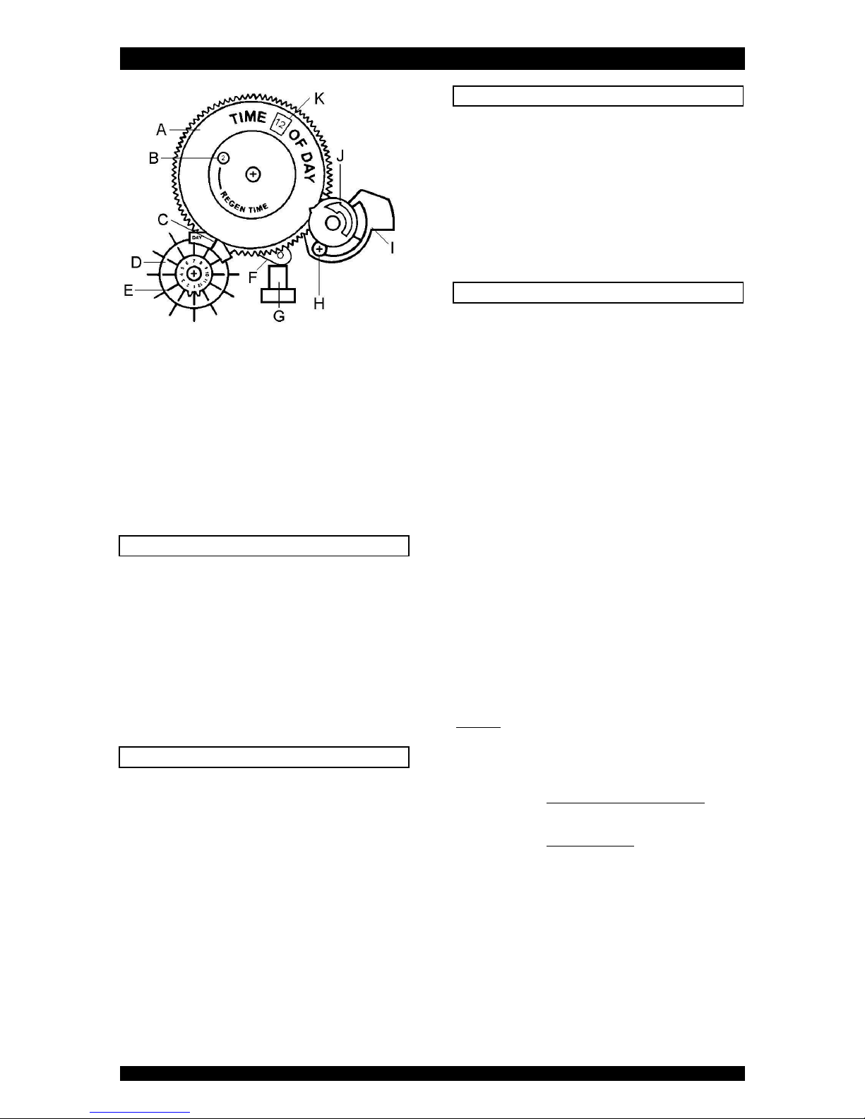
A clock plate
B time of regeneration window
C day indicator
D days skipper wheel
E skipper tabs
F actuator
G drain plunger
H locking screw
I brine/slow rinse section
J timer knob
K time of day window
POWER FAILURE
In the event of a power failure, the program will remain
unchanged, while the mechanical clock will stop;
consequently, in case of a power failure, the time of day
will not be maintained and will need to be set.
When the power failure occurs during the execution of an
automatic regeneration, the control valve will remain in
the regeneration position; when the power supply is re-
established, the control valve will resume the regeneration
from the point where it was interrupted.
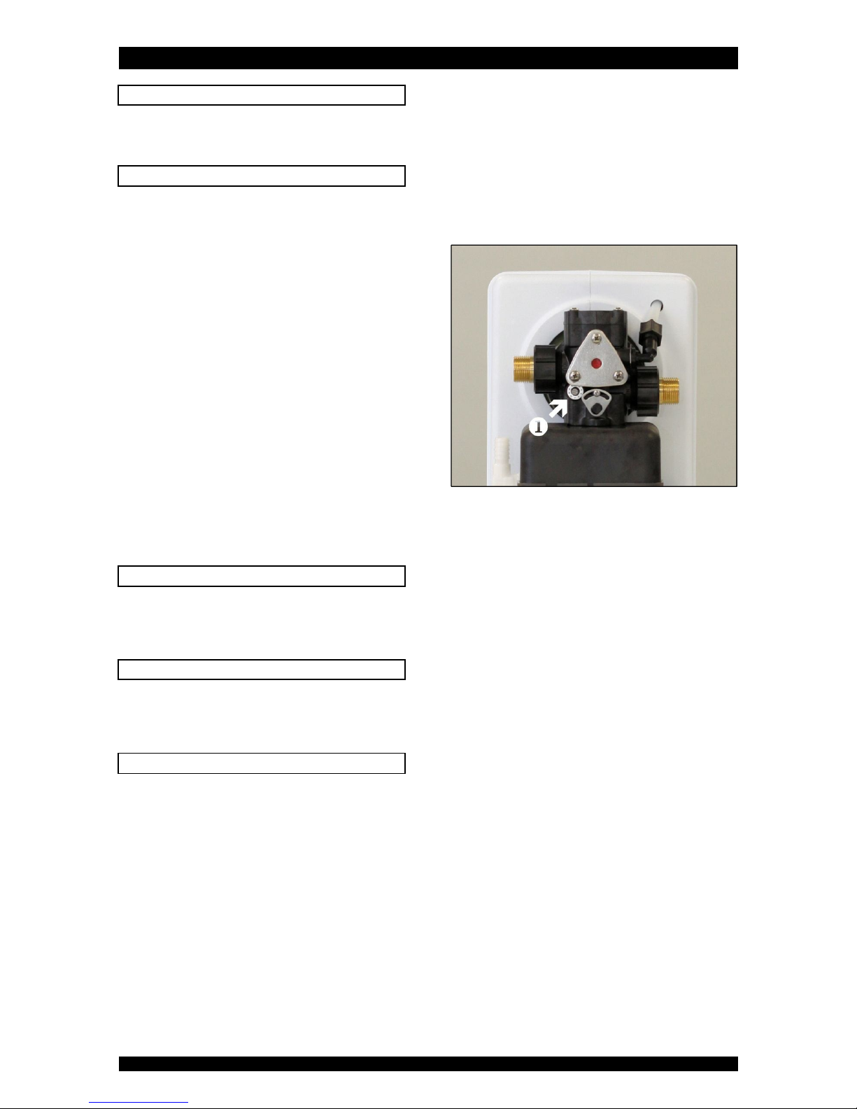
SERVICE / REGENERATION MODE
In service mode the drain plunger (G) will be closed. The
actuator (F) should NOT be visible.
In regeneration mode the drain plunger (G) will be pushed
down by the actuator (F). The actuator (F) will be visible.
The control valve can be reset to service mode at any time
by slowly turning the timer knob counter clockwise until
the drain plunger (K) is released again by the actuator (F).
MANUAL REGENERATION
It is possible to manually initiate a regeneration.
1. Push in the skipper tab (E) that is aligned with the day
indicator (C).
2. Turn the timer knob (K) counter clockwise, until the
time of day in the time of day window (L) equals the
time of regeneration in the time of regeneration
window (B).
3. The time of day and the skipper tab (E) must be reset,
when the regeneration is terminated.
PROGRAMMING INSTRUCTIONS
Before starting the programming sequence, make sure
that the control valve is in the service mode.
1. TIME OF REGENERATION:
Turn the clock plate (A) until the desired time of
regeneration appears in the time of regeneration
window (B).
2. TIME OF DAY:
Turn the timer knob (K) counter clockwise until the
correct time of day on the clock gear appears in
the time of day window (L).
3. REGENERATION FREQUENCY:
With all skipper tabs (E) pulled out, rotate the
skipper wheel (D) until day “1” is aligned with the
day indicator (C);
push in skipper tabs (E) which correspond with the
desired days of regeneration.
The regeneration frequency, i.e. the number of days of
service after which the system needs to be regenerated,
must be calculated, by dividing the nominal exchange
capacity of the system (see Technical Specifications) by:
1. the local water hardness,
2. the daily water usage.
Example:
Micro Budget 6
Water hardness = 19 °f
Water usage = 500 L/day = 0,5 m³/day
Regen freq. = nominal exchange capacity
water hardn. x daily water usage
= 31 m³x°f
19 °f x 0,5 m³/day
= 3,2 days
Regenerate every 2 days