BWS1500 Simple Install Guide 2
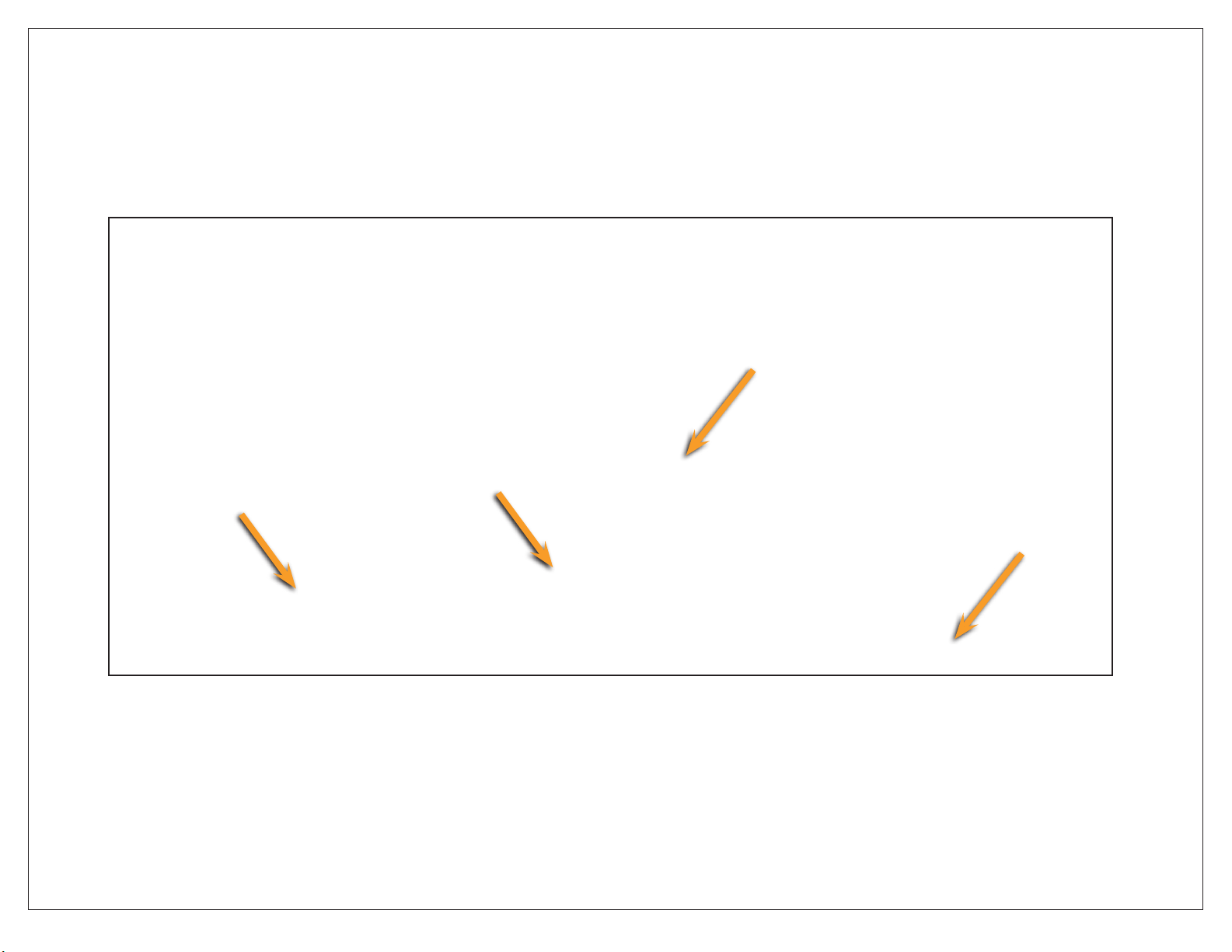
175 gal.
storage
tank
shown
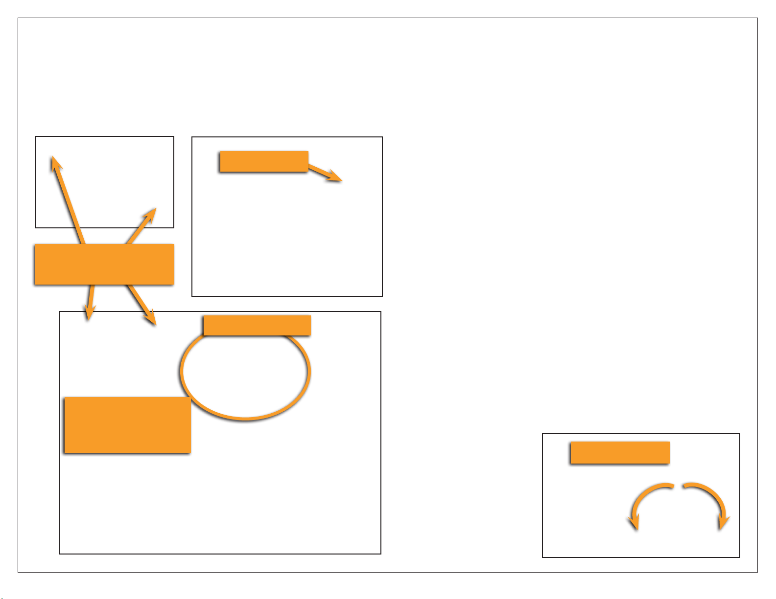
Completed
BWS1500 High
Flow Installation
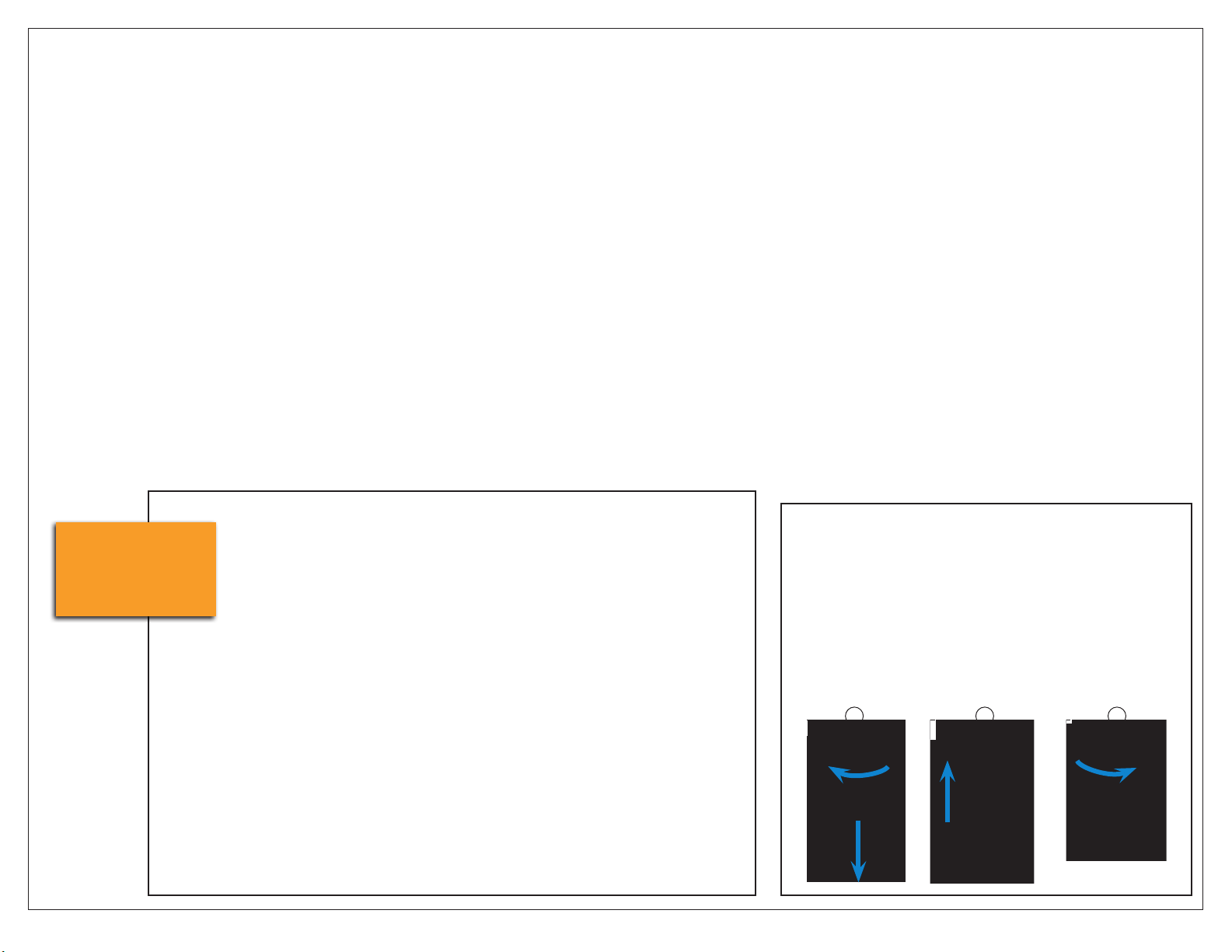
Installing or Replacing QT Cartridges
NOTE: Before installing or replacing QT Cartridges, make sure to remove
the plugs in the QT heads.
1. Close feed water valve.
2. Twist and pull down to remove cartridges.
3. Align the upward-pointing arrow on the new cartridge with the upward-
pointing arrow on the head. Push cartridge up into head until it stops.
4. Turn to right until it stops. NOTE: labels might not always face forward.
5. Open feed water valve.
234
System must be installed indoors
and easily accessed for service and
maintenance.
Water supply is cold water only, at a
minimum of 45 psi, maximum of 80 psi.
Distribution plumbing from the system
to equipment location(s) should be
minimum ¾” nominal. Hose, PEX or
other non-metal pipe is recommended.
Cut tubing and hoses to an appropriate
length and avoid loops or kinks in
tubing. Do not cut tubing with wire
crimpers or dikes. Route and secure
lines in an orderly manner.
Installation must conform to all local
codes and regulations.
Equipment layout:
Take time to visualize the nal
placement of equipment. Hose, tubing
and electrical connections will be
made between the Processor, Storage
Tank, RP Pump, Buffer Tank and the
distribution plumbing.
Consider the placement of components
in relation to the utilities (described
below), and allow easy access for
operation and service. For example,
make certain that an operator can see
and access the Emergency Bypass
Valve on the left side of the Processor;
and that the power cords from the
Processor and RP Pump can be routed
to the power outlet.
Utility requirements:
Water Supply – A minimum ½”
dedicated water supply line* with ½”
NFPT full-ow ball valve is required
within 6 feet of the processor. When
possible, locate the supply valve to
the left of the processor and install a
pressure gauge.
Drain – A drain with a capacity of 4
gallons per minute ow is required
within 4 feet of installation location.
Power – Two 120 VAC electrical outlets
are required; one for the Processor
and one for the RP Pump.
*NOTE: A dedicated supply line is a
water line run directly from a main
water source. It does not branch out
and is uninterrupted along its path.
vGeneral Information