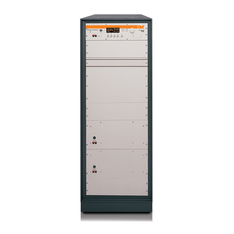
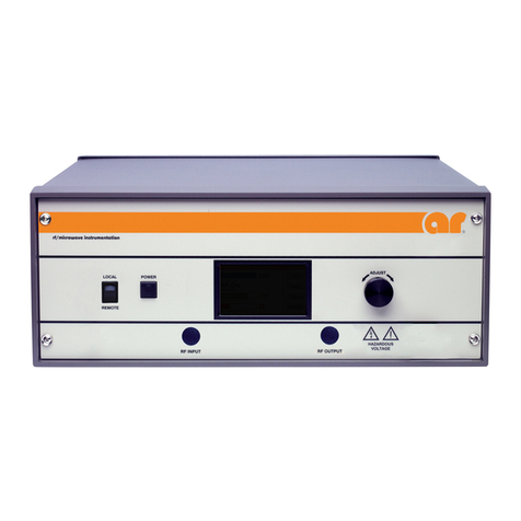
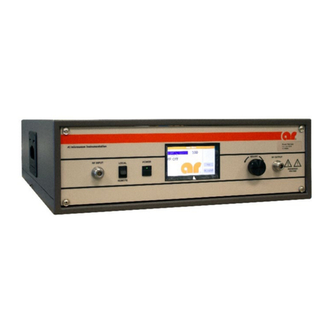
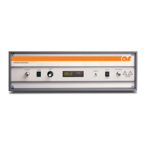
AR 200T4G8 Service manual

Operating and
Service Manual
200T4G8
Model
10006031
Part Number
Serial Number
160 School House Road, Souderton, PA 18964 • 215-723-8181 • Fax 215-723-5688 • www.arworld.us


EC Declaration of Conformity
We; Amplifier Research
160 School House Road
Souderton, PA 18964
declare that our product;
Models 200T1G2, 200T1G3, 250T1G3, 200T2G4, 200T2G8, 300T2G8,
200T4G8, 200T8G18, 250T8G18 RF amplifiers
to which this declaration relates is in compliance with the requirements of the EEC EMC
Directive (89/336/EEC) in accordance with the relative standards listed below:
EMC: EN 50081-1
EN 50082-1
prEN 50082-1
EN 55022 (1987) Class A
IEC 1000-4-2 (1995) 4kV (Air Discharge) AND 8kV (Contact Discharge)
ENV 1000-4-4 (1995) 1kV (Power Supply) AND 0.5kV (I/O Cables)
ENV 50142 (1995) 1kV (Power Supply)
ENV 501441 (1994) 3Vrms
The CE marking is affixed on the device according to article 10 of the EC Directive
89/336/EEC.
Donald R. Shepherd
President


INSTRUCTIONS FOR SAFE OPERATION
Revised 0517
Observe the following safety guidelines to help ensure your
own personal safety and to help protect your equipment and
working environment from potential damage.
INTENDED USE
This equipment is intended for general laboratory use in
generating, controlling, and measuring levels of
electromagnetic Radio Frequency (RF) energy. Ensure that the
device is operated in a location which will control the radiated
energy and will not cause injury or violate regulatory levels of
electromagnetic interference.
SAFETY SYMBOLS
These symbols may appear in your user manual or on
equipment.
This symbol is marked on the equipment when it
is necessary for the user to refer to the manual for
important safety information.
The caution symbol denotes a potential hazard.
Attention must be given to the statement to
prevent damage, destruction, or harm.
Dangerous voltages are present. Use extreme
care.
Indicates a terminal intended for connection to an
external conductor for protection against
electrical shock in case of a fault, or the terminal
of a protective earth (ground) electrode.
Indicates invisible laser radiation–do not view
directly with optical instruments.
Indicates frame or chassis ground connection
terminal.
Indicates alternating current.
Indicates this product must not be disposed of
with your other household waste.
Indicates that the marked surface and adjacent
surfaces can attain temperatures that may be hot
to the touch.
EQUIPMENT SETUP PRECAUTIONS
Review the user manual and become familiar with
all safety markings and instructions. Protection
provided by the equipment may be impaired if used
in a manner not specified by AR RF/Microwave
Instrumentation (AR).
•Follow all lifting instructions specified in this document.
•Place the equipment on a hard, level surface.
•Do not use the equipment in a wet environment, for
example, near a sink, or in a wet basement.
•Position your equipment so that the power switch is easily
accessible.
•Leave 10.2 cm (4 in) minimum of clearance on all vented
sides of the equipment to permit the airflow required for
proper ventilation. Do not restrict airflow into the
equipment by blocking any vents or air intakes. Restricting
airflow can result in damage to the equipment, intermittent
shut-downs or safety hazards.
•Keep equipment away from extremely hot or cold
temperatures to ensure that it is used within the specified
operating range.
•While installing accessories such as antennas, directional
couplers and field probes, take care to avoid any exposure
to hazardous RF levels.
•Ensure that nothing rests on your equipment’s cables and
that the cables are not located where they can be stepped
on or tripped over.
•Move equipment with care; ensure that all casters and/or
cables are firmly connected to the system. Avoid sudden
stops and uneven surfaces.
BEFORE APPLYING POWER
Your AR equipment may have more than one power supply
cable. Use only approved power cable(s). If you have not been
provided with a power cable for the equipment or for any AC-
powered option intended for the equipment, purchase a power
cable that is approved for use in your country. The power cable
must be rated for the equipment and for the voltage and current
marked on the equipment’s electrical ratings label.
Incorrectly installing or using an incompatible line
voltage may increase the risk of fire or other
hazards. To help prevent electric shock, plug the
equipment and peripheral power cables into properly grounded
electrical outlets. These cables are equipped with three-prong
plugsto help ensure proper grounding. Do notuse adapter plugs
or remove the grounding prong from a cable.
Do not modify power cables or plugs. Consult a licensed
electrician or AR trained service technician for equipment
modifications. Always follow your local/national wiring rules.
Do not operate the equipment if there is physical
damage, missing hardware, or missing panels.
SAFETY GROUND
This equipment is provided with a protective earth
terminal. The mains power source to the equipment
must supply an uninterrupted safety ground of
sufficient size to attach wiring terminals, power
cord, or supplied power cord set. DO NOT USE this equipment
if this protection is impaired.

INSTRUCTIONS FOR SAFE OPERATION
Revised 0517
HAZARDOUS RF VOLTAGES
The RF voltages on the center pin of an RF output
connector can be hazardous. The RF output
connector should be connected to a load before AC
power is applied to the equipment. Do not come into
contact with the center pin of the RF output connector or
accessories connected to it. Place the equipment in a non-
operating condition before disconnecting or connecting the load
to the RF output connector.
ACOUSTIC LIMITATIONS
If equipment noise exceeds 80dB, ear protection is required.
MAINTENANCE CAUTION
Adjustment, maintenance, or repair of the equipment must be
performed only by qualified personnel. Hazardous energy may
be present while protective covers are removed from the
equipment even if disconnected from the power source. Contact
may result in personal injury. Replacement fuses are required
to be of specific type and current rating.
ENVIRONMENTAL CONDITIONS
Unless otherwise stated on the product specification sheet, this
equipment is designed to be safe under the following
environmental conditions:
•Indoor use
•Altitude up to 2000m
•Temperature of 5°C to 40°C
•Maximum relative humidity 80% for temperatures up to
31°C. Decreasing linearly to 50% at 40°C.
•Main supply voltage fluctuations not to exceed ± 10% of
the nominal voltage or minimum and maximum
autoranging values.
•Pollution degree 2: Normally non-conductive with
occasional condensation. While the equipment will not
cause hazardous condition over this environmental range,
its performance may vary.
EQUIPMENT CONTAINING LASERS
AR Field Probes (FL/PL Series) and Field Analyzers
(FA Series) are Class 1 laser products containing
embedded Class 4 lasers. Under normal use, the
laser radiation is completely contained within the
fiber optic cables and poses no threat of exposure. Safety
interlocks ensure that the laser is not activated unless the cables
are properly connected. Always exercise caution when using
or maintaining laser products. Do not view directly with optical
instruments.
RF ANTENNAS
•This equipment (antenna or antenna assembly) may be
heavy, requiring two persons to lift. Use caution when
installing or removing unit. Follow all equipment setup and
lifting instructions specified in this document.
•Ensure connectors are appropriate for intended operation.
Connectors are specified in the user manual and product
specification sheet.
•Do not exceed the maximum RF input level stated in the
specifications. Refer to the user manual and product
specification sheet to determine the applicable RF levels.
•Excessive RF input could damage the equipment or
connectors, causing safety hazards.
•When in operation, the RF voltages on the antenna
elements can be hazardous. Do not come into contact with
the antenna or elements when the RF input connector is
connected to a live RF source.
•To avoid injury to personnel and accidental damage to
power amplifier or antenna, disable the RF output of power
amplifier before connecting or disconnecting the input
connection to the antenna.
•Perform periodic inspections of antenna and field probe
systems to verify calibration due date, proper operation,
and overall condition of equipment.
RACK MOUNTED TWT MODELS
Some TWT models are supplied without the removable
enclosure offered for benchtop use. These rack-mountable
models may be supplied with either carry handles or slides and
front handles installed. Follow all lifting instructions specified
in this document and installation instructions supplied in the
TWT user manual.
LIFTING INSTRUCTIONS FOR AR EQUIPMENT
Because most products must be
handled during distribution, assembly
and use, the risk of serious injury due
to unsafe product handling should be
a fundamental consideration of every
user. An authoritative guideline for
eliminating unwarranted risk of injury caused by lifting is
provided by the NIOSH Work Practices (Publication #94-110)
available at:
https://www.cdc.gov/niosh/docs/94-110/pdfs/94-110.pdf.
In general, observe the following guidelines for lifting a weight
of 50 lb or more:
•Use lifting eye (for floor standing) or side handles (table
top) to lift unit only.
•Use equipment of adequate capacity to lift and support unit.
•If using forklift to move unit, be sure forks are long enough
to extend beyond the side of the unit.
•For additional information, follow the link specified above.
Suggested Periodic Maintenance for TWT Amplifiers
1. Keep monthly log of the voltages, currents and temperatures as shown on Menus. Also record
Date, “Console” and “Operate” hours. Take readings in Operate mode with the gain at zero
(0%) percent. Leave unit in Operate mode for 20 minutes (Max Duty if Pulsed Unit), and then
record data. Review the log to identify trends and contact factory if required.
2. Keep monthly log of performance with active RF. At mid-band frequency, with Gain set to
100%, apply RF drive that will provide rated power. This will help indicate if the gain or power
is changing and if the traveling wave tube or pre-amp needs service. Record the following:
a. RF Drive Level
b. Forward Power
c. Reverse Power
d. Body Current (Iw)
e. Sample Port Power reading (if possible).
3. Remove air intake filter and clean using compressed air and/or vacuum cleaner.
4. Ensure air inlet and outlet are unobstructed.
5. Check that AC Input connections are secure. Make sure the AC cable is not damaged or
deteriorated.
6. Check that both input and output RF connections (waveguide or coax) are connected tightly and
un-damaged.
Rev A


TABLE OF CONTENTS
TABLE OF CONTENTS ...................................................................................................i
1. DESCRIPTION AND SPECIFICATIONS .............................................................1
1.1 TWTA Description ....................................................................................................1
1.2 Suggested Applications..............................................................................................1
1.3 Specifications.............................................................................................................1
1.4 Accessories.................................................................................................................1
1.5 Test Data Sheet ..........................................................................................................1
2. THEORY OF OPERATION.....................................................................................5
2.1 Design of the Amplifier .............................................................................................5
2.2 Description of the RF Circuit (A24380-030).............................................................5
2.3 Description of the Power Supply (A22520-090) .......................................................6
3. OPERATION .............................................................................................................7
3.1 Warnings and Cautions ..............................................................................................7
3.2 Installation..................................................................................................................8
3.2.1 Unpacking ...............................................................................................................8
3.2.2 Mounting.................................................................................................................8
3.2.3 Cooling Requirements.............................................................................................9
3.2.4 AC Line Power Connections...................................................................................9
3.2.5 RF Connections.....................................................................................................10
3.2.6 External interlock connector .................................................................................10
3.3 Front Panel Features.................................................................................................11
3.4 Front Panel Display and Soft Keys ..........................................................................12
3.5 Rear Panel Features..................................................................................................16
3.6 Initial Turn On and Warm-up Procedure .................................................................17
3.7 Emergency Bypass Operation ..................................................................................18
3.8 Remote IEEE-488 Operation ...................................................................................18
3.9 TWTA General Considerations................................................................................23
4. MAINTENANCE .....................................................................................................27
4.1 Safety Warning ........................................................................................................27
4.2 Unauthorized Repairs...............................................................................................27
4.3 Preventive Maintenance...........................................................................................27
4.4 Troubleshooting .......................................................................................................28
4.5 Non-Repairable Modules .........................................................................................29
5. TECHNICAL DOCUMENTATION......................................................................31
5.1 Top Level Build Tree...............................................................................................32
5.2 Schematics ...............................................................................................................33
5.3 Wiring Diagrams......................................................................................................35
5.4 Parts Lists.................................................................................................................37
5.4.1 Parts List-HPA Logic and Control Module, A16485-000 ....................................38
5.4.2 Parts List-C-Band Power Supply for TWT 5889, A22520-090............................40
5.4.3 Parts List-HPA System Control Front Panel, A24324-000 ..................................41
5.4.4 Parts List-Remote Control Board, A24369-000....................................................42
5.4.5 Parts List-Microwave Power Assembly 200C, A24380-030 ................................43
5.4.6 Parts List-HPA Interface Board (Plastic), A25444-000........................................44
i

Model 200T4G8
5.4.7 Parts List-200 Watt C Band TWTA, AR 10-1/2, A28880-932.............................47
5.5 Recommended Spare Parts.......................................................................................48
5.6 Sample Program for IEEE-488 Communication......................................................49
FIGURES AND TABLES
Figure 3-1. Rear View of HPA...........................................................................................8
Figure 3-2. TWTA Front Panel Features..........................................................................11
Figure 3-3. Front Panel Display Screens..........................................................................12
Figure 3-4. TWTA Rear Panel Features...........................................................................16
Table 1-1. Specifications for Model 200T4G8....................................................................2
Table 1-2. Model Configurations .......................................................................................3
Table 3-1. Front Panel Features .......................................................................................11
Table 3-2. TWTA Rear Panel Features ............................................................................16
Table 3-3. Catalog of IEEE-488 Commands....................................................................18
Table 3-4. Catalog of Status Codes ..................................................................................20
Table 3-5. Catalog of Fault Codes....................................................................................20
Table 3-6. Catalog of System State Codes .......................................................................21
Table 3-7. *STA?; Response Codes.................................................................................21
Table 3-8. *STB?; Response Codes .................................................................................22
Table 3-9. Catalog of Heater Auto Off TimeDelay Codes..............................................22
ii

1. DESCRIPTION AND SPECIFICATIONS
This manual provides operating, interfacing and selected service information pertinent to Amplifier
Research Model 200T4G8 Broadband Microwave Amplifier. The Model 200T4G8 is a 200 watt C band
traveling-wave tube amplifier (TWTA).
1.1 TWTA DESCRIPTION
The amplifier uses a 250 watt traveling wave tube (TWT) to provide 200 watts minimum output over the
TWT amplifier's full bandwidth. The amplifier is well suited for susceptibility and general laboratory testing
where instantaneous bandwidth and high gain are required.
The amplifier is completely self-contained and packaged for standard 19-inch rack mounting or bench top
use. The front panel of the rack mountable amplifier is 10.5 inches high, and the overall unit is 25.25 inches
deep, excluding the rear-panel connectors. For bench top use, the amplifier is supplied in an enclosure with
integral carrying handles.
Primary power is 190-260 volts 50-60 Hz., single phase. An efficient switching power supply design
provides minimum power consumption. A fast regulation control loop and a high degree of filtering ensure
performance within specifications over a wide range of operating conditions. The amplifier is fully enclosed,
and the lower panel of the rack mountable amplifier is interlocked to reduce the likelihood of accidental
contact with high voltage.
1.2 SUGGESTED APPLICATIONS
•RF Susceptibility testing
•Antenna and component testing
•Equipment calibration
•General laboratory instrumentation
1.3 SPECIFICATIONS
Refer to the Amplifier Research Data Sheet on the following pages for detailed specifications.
1.4 ACCESSORIES
Amplifier Research offers a number of accessories for use with this amplifier including:
•Directional coupler
•Antenna
•Flexible transmission line
Refer to a current Amplifier Research catalogue for Microwave Accessories.
1.5 TEST DATA SHEET
A Test Data Sheet for a specific unit is prepared at the time of manufacture and is included with the unit's
copy of this manual.
Rev. F 1

Model 200T4G8
2 Rev F

Modular design of the power supply and RF
components allow for easy access and repair.
Use of a switching mode power supply results
in significant weight reduction.
Housed in a stylish contemporary cabinet, this
unit is designed for benchtop use but can be
removed from cabinet for rack mounting. The
Model 200T4G8 provides readily available RF
power for a variety of applications in Test and
Measurement, (including EMC RF susceptibility
testing), Industrial and University Research and
Development, and Service applications.
See Model Configuration for package alterna-
tives.
The export classification for this equipment is
EAR99. These commodities, technology or
software are controlled for export in accord-
ance with the U.S. Export Administration Regu-
lations. Diversion contrary to U.S. law is pro-
hibited.
The Model 200T4G8 is a self contained,
forced air cooled, broadband traveling wave
tube (TWT) microwave amplifier designed for
applications where instantaneous bandwidth
and high gain are required. A reliable 250
watt TWT provides a conservative 200 watts
minimum at the amplifier output connector.
Stated power specifications are at the funda-
mental frequency.
The amplifier's front panel digital display
shows forward and reflected output plus exten-
sive system status information accessed
through a series of menus via soft keys. Status
indicators include power on, warm-up,
standby, operate, faults, excess reflected power
warning and remote. Standard features in-
clude a built-in IEEE-488 (GPIB) interface, 0
dBm input, VSWR protection, gain control, RF
output sample port, plus monitoring of TWT
helix current, cathode voltage, collector volt-
age, heater current, heater voltage, baseplate
temperature and cabinet temperature.
Features
Specifications
200T4G8
M1, M3–M5
200 Watts CW
4GHz–8GHz
AR RF/Microwave
Instrumentation
160 School House Rd
Souderton, PA 18964
215-723-8181
For an applications engi-
neer call:800.933.8181
www.arworld.us

POWER (fundamental), CW, @ OUTPUT
CONNECTOR:
Nominal: 262 watts
Minimum: 200 watts
Linear @ 1 dB Compression: 100 watts minimum
FLATNESS: ±6 dB maximum at rated power
FREQUENCY RESPONSE: 4-8 GHz instantaneously
INPUT FOR RATED OUTPUT: 1.0 milliwatt maximum
GAIN (at maximum setting): 53 dB minimum
GAIN ADJUSTMENT (continuous range): 35 dB mini-
mum
INPUT IMPEDANCE: 50 ohms, VSWR 2.0:1 maximum
OUTPUT IMPEDANCE: 50 ohms, VSWR 2.5:1 typical
MISMATCH TOLERANCE: Output power foldback
protection at reflected power exceeding 40 watts. Will
operate without damage or oscillation with any magni-
tude and phase of source and load impedance. May
oscillate with unshielded open due to coupling to in-
put. Should not be tested with connector off.
MODULATION CAPABILITY: Will faithfully reproduce
AM, FM, or pulse modulation appearing on the input
signal. AM peak envelope power limited to specified
power.
NOISE POWER DENSITY: Minus 64 dBm/Hz maxi-
mum; Minus 70 dBm/Hz, typical
HARMONIC DISTORTION: Minus 4 dBc maximum;
Minus 7.0 dBc typical
PRIMARY POWER: 190-260 VAC, 50/60 Hz single
phase, 2.0 KVA maximum
CONNECTORS:
RF input: Type N female on rear panel
RF output: Type N female on rear panel
RF output sample port: Type N female on rear panel
GPIB: IEEE (f) on rear panel
Interlock: DB-15 (f) on rear panel
COOLING: Forced air (self contained fans), air entry
and exit in rear.
EXPORT CLASSIFICATION: EAR99
Page 2
Specifications
200T4G8
M1, M3–M5
200 Watts CW
4GHz–8GHz
Model Configurations
To order AR Products, call 215.723.8181. For an applications engineer call:800.933.8181. Direct to Service call: 215.723.0275 or
Approved for public release by AR RF/Microwave Instrumentation 072116
Model Number Description Weight Size (W x H x D)
200T4G8 With removable enclosure 54 kg (120 lb) 50.3 x 29.7 x 68.6 cm
200T4G8M1 Shipped without an outer cabinet 41 kg (90 lb) 48.3 x 26.7 x 68.6 cm
200T4G8M3 Enclosure removed for rack mounting – 43 kg (95 lb) 48.3 x 26.7 x 68.6 cm
200T4G8M4 See separate specification sheet.
200T4G8M5 Enclosure removed. Side carry handles 41 kg (90 lb) 48.3 x 26.7 x 68.6 cm

2. THEORY OF OPERATION
2.1 DESIGN OF THE AMPLIFIER
The Model 200T4G8 TWT amplifier consists of four principal subsystems. Two of these subsystems, the
microwave power assembly (A24380-030) and the TWT power supply (A22520-090) are discussed in
sections 2.2 and 2.3, respectively.
The other two subsystems are the microprocessor control system and the TWTA packaging. These both
consist of a number of subassemblies. See the build tree in section 5.1 for further information about how the
parts lists are structured.
The heart of the microprocessor control system is the control head assembly (A26946-300) and the HPA
display board (A22700-900). The microprocessor control system supervises the power supply, provides
metering display, processes operator front panel input, and enables communication with a host computer over
the IEEE-488 interface.
The control head is provided with its own power supply and, other than thru the IEEE-488 interface bus, is
electrically isolated from the amplifier. Communication with the amplifier is via fiberoptic links to the HPA
interface assembly (A25444-000).
The TWTA packaging consists of a cabinet assembly (A24381-030), a cooling system (A24382-000) utilizing
a DC powered backwards curved impeller blower and a DC power supply, and various chassis wiring
components.
2.2 DESCRIPTION OF THE RF CIRCUIT (A24380-030)
The TWTA consists of two stages of RF amplification: a solid state preamp assembly with adjustable gain
(E01198-000) and a traveling-wave tube amplifier (E30069-000).
The type N RF input connector is located on the rear panel. The RF input is fed to the input connector on the
solid state preamp. The solid state preamp's output drives the RF input of the TWT. The RF output of the
TWT is a type N female connector. The output is directed through a cable to a dual coaxial -30 dB directional
coupler. The output of the coupler is a type N female connector, which protrudes through the rear panel to
serve as the amplifier’s RF output connector.
The reverse port on the directional coupler is connected to a detector diode, whose output is used for VSWR
protection by the power supply logic board, for VSWR measurement in the leveling loop, and for reverse
power measurement on the HPA interface board.
The forward port output is split by a -3 dB splitter. One output is connected to a detector diode via a pad. The
output of the detector is used on the HPA interface board to measure forward power. The other port of the
splitter is connected to the RF sample port on the rear panel. A pad between the splitter and the port isolates
the forward power measurement from mismatches at the sample port.
Amplifier gain is determined by the solid state preamp (SSA), which has a voltage-controlled attenuator. The
control head determines the output of a digital-to-analog converter (DAC) on the HPA interface board. The
output of the DAC controls the SSA attenuator. The remote control board (A24369-000) mounted behind the
front panel is provided with a circuit that increases the attenuation so that reverse power is limited to a safe
level (on the order of 20 to 50 watts). In emergency bypass operation (see section 3.7) the attenuator signal is
Rev. F 5

Model 200T4G8
provided locally on the remote control board. The foldback circuit remains on line in emergency bypass
operation.
2.3 DESCRIPTION OF THE POWER SUPPLY (A22520-090)
The TWT power supply is of modular construction. Low voltage power for logic and control of the entire
power supply assembly, the preamplifier, and the HPA interface board is provided by the low voltage power
supply module (A23687-001). Control logic and TWT protection circuits are contained in the HPA logic and
Control Assembly (A16485-000).
The Heater Power Supply Module (A10010-000) powers the TWT DC heater..
The high voltage power supply consists of the following: the Power Factor Correction module (A23683-000)
converts line voltage to DC for the high voltage switching supply. Switching transistors are on the Power
Board Assembly (A16487-001), and switching is controlled by the Pulse Width Modulation (PWM) Board
(A10017-090). The high voltage transformer and rectifiers are contained in the High Voltage Diode/Cap
Assembly (A21425-090). The high voltage DC is filtered in the HV Filter Assembly (A21457-001).
Interconnects between the power supply modules are through a motherboard. It is installed in a finned heat
sink assembly to which the modules are bolted. The heat sink is cooled by the incoming cabinet air. The Heat
Sink/Motherboard assembly is A24357-000.
6 Rev. F

3. OPERATION
3.1 WARNINGS AND CAUTIONS
Throughout this manual, the symbol:
WARNING:
indicates that a hazard exists that may result in personal injury or loss of life.
CAUTION:
indicates that failure to follow procedures may result in damage to the
equipment.
WARNING: DANGER - High Voltage Present:
Electrical equipment in this TWTA generates and stores high-voltage
energy that can result in fatal electrocution. Do not operate the TWTA
with covers or the front panel removed.
Service work must be performed only by technicians thoroughly familiar
with the high-voltages present in microwave tube amplifiers in general,
and with this equipment in particular.
Never handle the TWT leads or the high-voltage connectors unless the
unit has been unplugged and it has been positively established that the
high-voltage filter capacitors have been discharged to a known safe level.
WARNING: Safety Ground
Improper grounding of this equipment can result in electric shock. The
TWTA must be operated only with a line cord with a safety ground wire.
It is the user's responsibility to ascertain that the power connector is
properly wired and that the power outlet is grounded.
WARNING: Explosive Atmosphere
To avoid explosion, never operate this TWTA in an explosive atmosphere.
This equipment is not certified for operation in an explosive atmosphere.
Rev. F 7

Model 200T4G8
3.2 INSTALLATION
3.2.1 Unpacking
Upon receiving the TWTA, unpack the unit and inspect it for obvious signs of external damage. If damage is
observed, notify the carrier and contact an authorized service representative.
Save and store the shipping container in case the unit needs to be returned in the future for calibration or
repair.
3.2.2 Mounting
The TWTA may be operated as a standalone benchtop unit, or it may be installed in a 19" rack.
If rack mounting is desired, first remove the amplifier from the cabinet, then install the amplifier in the rack.
NOTE: Due to the weight of the unit, the lifting and removal of the amplifier from the cabinet is an operation
requiring two people.
Before removal disconnect power, RF and any other interface connectors. On the rear of the unit, remove any
screws used to connect transport brackets to amplifier (two on each bracket). Reinstall screws in holes in
chassis. On the front of the unit, remove the four screws (two outside screws on each side) mounting the front
panel to the cabinet. Carefully slide the amplifier out of the front of the cabinet.
CAUTION:
Never rack mount the TWTA using the front panel alone. The chassis is
likely to be damaged unless its weight is supported. Bottom support rails
must be provided in a rack mount configuration.
See Figure 3-1 (below) for the locations of threaded holes that may be used for supplementary support of the
rear of the TWTA for transport. Screws installed in these threaded holes may be removed and replaced with
screws of appropriate length to thread 3/8 - 5/8 inch into the TWTA chassis.
RF OUT
EXTERNAL INTERLOCK
J3
-40dB
RF SAMPLE
A1J2
0 dBM MAX
RF IN
A1J1
50-60 HZ.
190-260 VAC
AC IN
J1
IEEE-488
REMOTE
J2
INTERFACE
8-32 TAPPED HOLES
19.00
16.130 FOR REAR SUPPORT
(4 PLACES)
16.130
1.840
0.750
10.50
0.65
Figure 3-1. Rear View of HPA
8 Rev. F

Model 200T4G8
For rack mount installation of multiple units, the units should be separated vertically by at least 1 3/4 inches.
This will allow room for necessary support rails and facilitate installation and removal of the units.
3.2.3 Cooling Requirements
The TWTA is provided with a cooling fan. It is important that air movement around the rear of the unit be
unobstructed.
CAUTION:
For either bench or rack mounting, do not position the TWTA in such a
way that the air intake or outlet are blocked, or that the exhaust flow is
directed into the intake. See Paragraph 3.5 for location of air intake and
air outlet. If the unit is rack mounted, make sure that the intake air is
45°C or below. If necessary, fabricate a short duct to direct the hot
exhaust air out of the rack enclosure. Great care must be taken to
minimize any exhaust air restrictions. Avoid mounting heat-producing
equipment in the same rack, especially below the TWTA. Failure to
provide adequate cooling can result in the unit shutting down from over
temperature conditions.
The TWTA dissipates approximately 1.5 kilowatts when in the operate mode.
3.2.4 AC Line Power Connections
AC line power connection to the TWTA is made at the AC inlet J1, which is a female IEC-320 16A
connector. The connector is provided with a bracket that can be used to secure the plug from accidental
withdrawal. A line cord suitable for the type of AC outlet used, and consistent with local electrical codes,
must be obtained to mate with J1. Minimum wire size recommended for the line cord is 1.5 mm² (16 AWG).
Units are provided with an unterminated 3-wire cord. To use this line cord it should be terminated with a
suitable plug to a 190 to 260 VAC 50-60 Hz. single-phase source as follows:
Color Function
International Harmonized North American
Brown Black Line
Blue White Neutral
Yellow/Green Green Safety Ground
CAUTION:
Connect plug to J1 and secure plug with bracket only when no AC is
supplied to the cord.
Rev. F 9

Model 200T4G8
3.2.5 RF Connections
The RF output connector is type N female coaxial connector.
CAUTION:
Never operate the TWTA without a matched output load rated for at least
350 watts, continuous. The TWTA is not provided with an output
isolator. Full reflected power may irreparably damage the TWT. Even
with no drive, "looping" oscillation can result in RF output high enough
to damage the tube if it is operated without a load. The VSWR detection
and foldback circuit is provided to protect the tube from progressive
failure or mismatch of the output load; it should not be relied on for
protection from the absence of a load.
If an external isolator is installed at the output of the TWTA, either the isolator should have a load capable of
dissipating the full output of the TWTA or the isolator load should be provided with a temperature sensing
switch. The temperature switch should be normally closed, self-resetting, and with a temperature rating such
that there is no possibility of damaging the load by overheating before the switch opens. The TWTA may be
interlocked with the switch by connecting it between pins 3 and 4 of the external interlock connector (J3). If
no external isolator is used, install a jumper between pins 3 and 4. See section 3.2.6, External Interlock
Connector, below.
3.2.6 External interlock connector
The TWTA is provided with external interlock capability via a 15-pin female D-sub connector, J3. To enable
the high voltage power supply, it is necessary to provide continuity between J3 pins 3 and 4. If the amplifier
shuts down because the interlock was opened, it will be necessary to reset the system to return to standby (see
System shutdown screen in Section 3.4). In addition, there is an external inhibit capability via the same
connector, J3. To enable RF ON (beam on), continuity must be provided between J3 pins 10 and 11. If
continuity is broken, the TWT beam will shut off until continuity is restored. No reset is required to return to
RF ON. Users may adopt the interlock and inhibit features to disable the HPA for either equipment protection
or as a backup for personnel protection.
CAUTION:
Do not rely solely on the external interlock or inhibit features for
personnel protection. Use proper operating and safety procedures to
insure that power is removed as necessary for personnel safety.
The amplifier has an internal jumper between J3 pins 1 and 2 that may be used by the customer to verify
installation of the HPA in the overall system by means of a continuity string.
10 Rev. F
This manual suits for next models
5
Table of contents
Other AR Amplifier manuals