AR 50W1000D Service manual

Operating and
Service Manual
50W1000D
Model
10043107
Part Number
Serial Number
160 Schoolhouse Road, Souderton, PA18964 • 215-723-8181 • Fax 866-859-0582 • www.arworld.us


Declaration of Conformity
Issue Date:
Model #/s:
Type of Equipment:
Function:
October 2020
Model 50W1000D Series
RF Broadband Amplifier
Designed tobe used ina RFimmunity test system or for research. The unit isintended toamplify an RF
signal and inject it into a load.
The equipment described above is declared to be in conformity with the following applicable national and international standards.
The conformity is valid only when equipment is used in a manner consistent with the manufacturer’s recommendations and the
reference documents.
EMC:
DIRECTIVE 2014/30/EU of the European Parliament and of the Council of 26 February 2014 on the harmonisation of the laws of
the Member States relating to electromagnetic compatibility
EN 61326-1:2013 Electrical equipment for measurement, control and laboratory use–EMC requirements–Part 1: General
Requirements
SAFETY:
DIRECTIVE 2014/35/EU of the European Parliament and of the Council of 26 February 2014 on the harmonisation of the laws of
the Member States relating to the making available on the market of electrical equipment designed for use within certain voltage
limits
CENELEC EN 61010-1 Issued 2010/10/01 Ed: 3
Safety Requirements for Electrical Equipment for Measurement Control and Laboratory Use – Part 1: General Requirements
UL 61010-1 Issued 2012/05/11 Ed: 3
Safety Requirements for Electrical Equipment for Measurement Control and Laboratory Use – Part 1: General Requirements
CAN/CSA C22.2 #61010-1 Issued 2012/05/11 Ed: 3
Safety Requirements for Electrical Equipment for Measurement Control and Laboratory Use – Part 1: General Requirements
HAZARDOUS SUBSTANCES (RoHS):
DIRECTIVE 2011/65/EU of the European Parliament and of the Council of 8 June 2011 on the restriction of the use of certain
hazardous substances in electrical and electronic equipment (recast)
Commission Delegated Directive (EU) 2015/863 of 31 March 2015 amending Annex II to Directive 2011/65/EU of the European
Parliament and of the Council as regards the list of restricted substances
Directive (EU) 2017/2102 of the European Parliament
and of the Council of 15 November 2017 amending Directive
2011/65/EU on the restriction of the use of certain hazardous substances in electrical and electronic equipment
RECYCLING (WEEE):
DIRECTIVE 2012/19/EU of the European Parliament and of the Council of 4 July 2012 on waste electrical and electronic
equipment (WEEE) (recast)
SUBSTANCES OF VERY HIGH CONCERN (REACH):
REGULATION (EC) 1907/2006 of the European Parliament and of the Council of 18 December 2006 concerning the
Registration, Evaluation, Authorization and Restriction of Substances of Very High Concern Chemicals (SVHC)
Supporting documentation is held by AR RF/Microwave Instrumentation’s Quality department in Pennsylvania, United States.
Place of issue: AR RF/Microwave Instrumentation
160 Schoolhouse Road
Souderton, Pennsylvania 18964 USA
Authorized officer of the company:
Patricia Thrasher
Manager Quality & Service


Instructions for European EMC Conformity
WARNING
It is the responsibility of the user of this equipment to provide electromagnetic shielding, filtering and isolation which
is necessary for EMC compliance to Directive 2014/30/EU. The equipment must therefore be operated in a shielded
area which provides a sufficient level of attenuation to meet the radiated emissions and immunity specifications. The
following minimum levels are suggested for use in accordance with the rated power of the equipment.
Rated Power
Minimum shielding attenuation
100 watts
50 dB
101 - 1000 watts
60 dB
1001 - 10,000 watts
70 dB
Since this equipment is designed to generate high levels of Radio Frequency energy, it is also essential that the user
read and follow the “Instructions for Safe Operation” in this manual. If other equipment is operated in the shielded
room it may be disturbed by the amplifier.
ACHTUNG
Der Benutzer dieses Gerätes ist dafür verantwortlich, daß die elektromagnetische Abschirmung und Filterung
gewährleistet ist, welche gemäß Richtlinie 2014/30/EU notwendig ist. Das Gerät muß deshalb in einem geschirmten
Raum betrieben werden, welcher eine ausreichenden Schirmung bietet, um die Emissions- und
Störfestigkeitsspezifkation einzuhalten. Es werden folgenden Minimalwerte der Schirmdämpfung und Filterung in den
unterschiedlichen Leistungsklassen empfohlen.
Hochfrequenzleistung
min. Schirmdämpfung
100 Watt
50 dB
101-1000 Watt
60 dB
1001-10.000 Watt
70 dB
Falls andere elektrische oder elektronische Geräte gleichzeitig mit dem Gerät betrieben werden, kann es zu
Beeinflussungen kommen. Da das Gerät zur Erzeugung von Hochfrequenzenergie dient ist es daher auch unbedingt
notwendig, daß der Benutzer die Sicherheitsvorschriften in der Bedienungsanleitung liest und einhält.
AVERTISSEMENT
Il est de la responsabilité de l'utilisateur de cet équipement d'assurer la protection électromagnétique, le filtrage et
l'isolation nécessaires, afin de se conformer à la directive 2014/30/EU concernant la C.E.M. Par conséquent, cet
équipement doit être mis en fonctionnement dans une enceinte d'atténuation suffisante pour satisfaire aux
spécifications d'émissivité et de susceptibilité. Pour une utilisation conforme, les niveaux d'atténuation minimums
suivants sont suggérés en fonction de la puissance de sortie de l'équipement:
Puissance de sortie
Atténuation minimum de l'enceinte
100 Watts
50 dB
101 à 1.000 Watts
60 dB
1.001 à 10.000 Watts
70 dB
Puisque cet équipement est destiné à générer de forts niveaux R.F., il est essentiel que l'utilisateur se conforme aux
instructions de sécurité indiquées dans ce manuel. Tout autre équipement en fonctionnement dans la cage de Faraday
peut-être perturbé par 1'amplificateur.


INSTRUCTIONS FOR SAFE OPERATION
Revised 0517
Observe the following safety guidelines to help ensure your
own personal safety and to help protect your equipment and
working environment from potential damage.
INTENDED USE
This equipment is intended for general laboratory use in
generating, controlling, and measuring levels of
electromagnetic Radio Frequency (RF) energy. Ensure that the
device is operated in a location which will control the radiated
energy and will not cause injury or violate regulatory levels of
electromagnetic interference.
SAFETY SYMBOLS
These symbols may appear in your user manual or on
equipment.
This symbol is marked on the equipment when it
is necessary for the user to refer to the manual for
important safety information.
The caution symbol denotes a potential hazard.
Attention must be given to the statement to
prevent damage, destruction, or harm.
Dangerous voltages are present. Use extreme
care.
Indicates a terminal intended for connection to an
external conductor for protection against
electrical shock in case of a fault, or the terminal
of a protective earth (ground) electrode.
Indicates invisible laser radiation–do not view
directly with optical instruments.
Indicates frame or chassis ground connection
terminal.
Indicates alternating current.
Indicates this product must not be disposed of
with your other household waste.
Indicates that the marked surface and adjacent
surfaces can attain temperatures that may be hot
to the touch.
EQUIPMENT SETUP PRECAUTIONS
Review the user manual and become familiar with
all safety markings and instructions. Protection
provided by the equipment may be impaired if used
in a manner not specified by AR RF/Microwave
Instrumentation (AR).
•Follow all lifting instructions specified in this document.
•Place the equipment on a hard, level surface.
•Do not use the equipment in a wet environment, for
example, near a sink, or in a wet basement.
•Position your equipment so that the power switch is easily
accessible.
•Leave 10.2 cm (4 in) minimum of clearance on all vented
sides of the equipment to permit the airflow required for
proper ventilation. Do not restrict airflow into the
equipment by blocking any vents or air intakes. Restricting
airflow can result in damage to the equipment, intermittent
shut-downs or safety hazards.
•Keep equipment away from extremely hot or cold
temperatures to ensure that it is used within the specified
operating range.
•While installing accessories such as antennas, directional
couplers and field probes, take care to avoid any exposure
to hazardous RF levels.
•Ensure that nothing rests on your equipment’s cables and
that the cables are not located where they can be stepped
on or tripped over.
•Move equipment with care; ensure that all casters and/or
cables are firmly connected to the system. Avoid sudden
stops and uneven surfaces.
BEFORE APPLYING POWER
Your AR equipment may have more than one power supply
cable. Use only approved power cable(s). If you have not been
provided with a power cable for the equipment or for any AC-
powered option intended for the equipment, purchase a power
cable that is approved for use in your country. The power cable
must be rated for the equipment and for the voltage and current
marked on the equipment’s electrical ratings label.
Incorrectly installing or using an incompatible line
voltage may increase the risk of fire or other
hazards. To help prevent electric shock, plug the
equipment and peripheral power cables into properly grounded
electrical outlets. These cables are equipped with three-prong
plugsto help ensure proper grounding. Do not use adapter plugs
or remove the grounding prong from a cable.
Do not modify power cables or plugs. Consult a licensed
electrician or AR trained service technician for equipment
modifications. Always follow your local/national wiring rules.
Do not operate the equipment if there is physical
damage, missing hardware, or missing panels.
SAFETY GROUND
This equipment is provided with a protective earth
terminal. The mains power source to the equipment
must supply an uninterrupted safety ground of
sufficient size to attach wiring terminals, power
cord, or supplied power cord set. DO NOT USE this equipment
if this protection is impaired.

INSTRUCTIONS FOR SAFE OPERATION
Revised 0517
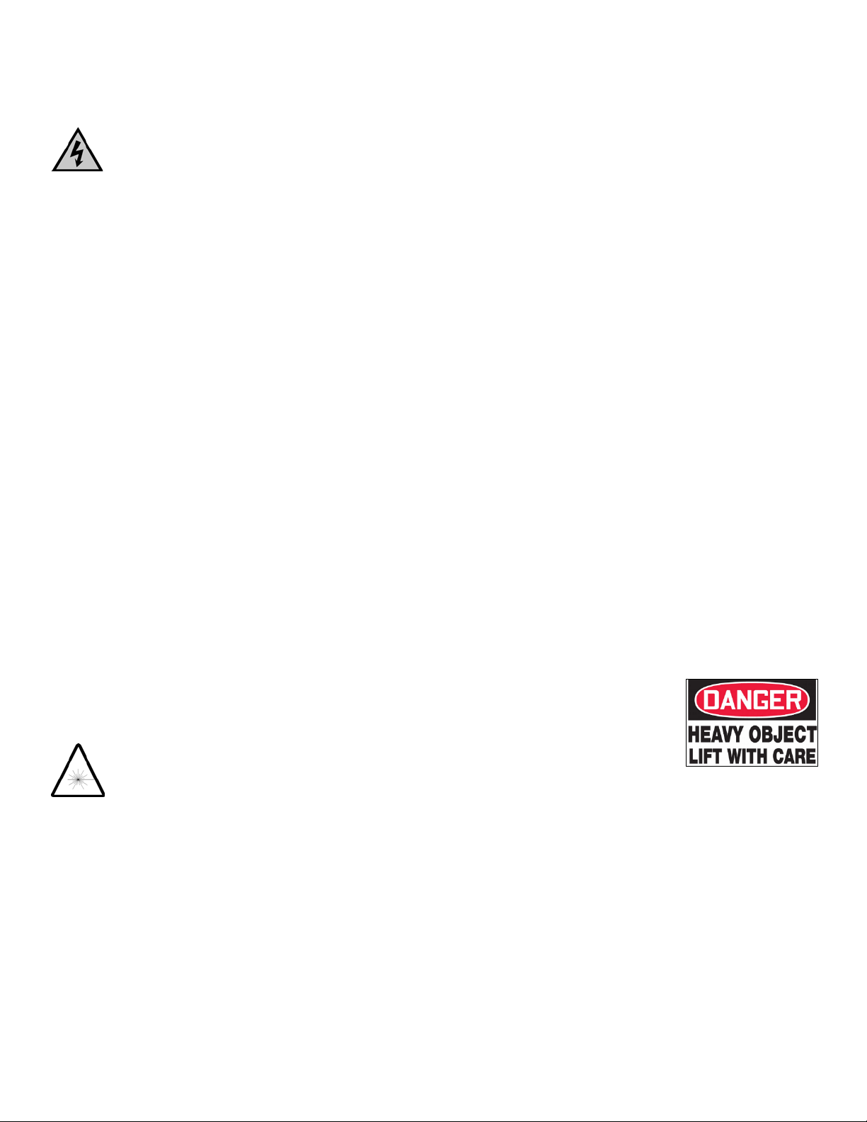
HAZARDOUS RF VOLTAGES
The RF voltages on the center pin of an RF output
connector can be hazardous. The RF output
connector should be connected to a load before AC
power is applied to the equipment. Do not come into
contact with the center pin of the RF output connector or
accessories connected to it. Place the equipment in a non-
operating condition before disconnecting or connecting the load
to the RF output connector.
ACOUSTIC LIMITATIONS
If equipment noise exceeds 80dB, ear protection is required.
MAINTENANCE CAUTION
Adjustment, maintenance, or repair of the equipment must be
performed only by qualified personnel. Hazardous energy may
be present while protective covers are removed from the
equipment even if disconnected from the power source. Contact
may result in personal injury. Replacement fuses are required
to be of specific type and current rating.
ENVIRONMENTAL CONDITIONS
Unless otherwise stated on the product specification sheet, this
equipment is designed to be safe under the following
environmental conditions:
•Indoor use
•Altitude up to 2000m
•Temperature of 5°C to 40°C
•Maximum relative humidity 80% for temperatures up to
31°C. Decreasing linearly to 50% at 40°C.
•Main supply voltage fluctuations not to exceed ± 10% of
the nominal voltage or minimum and maximum
autoranging values.
•Pollution degree 2: Normally non-conductive with
occasional condensation. While the equipment will not
cause hazardous condition over this environmental range,
its performance may vary.
EQUIPMENT CONTAINING LASERS
AR Field Probes (FL/PL Series) and Field Analyzers
(FA Series) are Class 1 laser products containing
embedded Class 4 lasers. Under normal use, the
laser radiation is completely contained within the
fiber optic cables and poses no threat of exposure. Safety
interlocks ensure that the laser is not activated unless the cables
are properly connected. Always exercise caution when using
or maintaining laser products. Do not view directly with optical
instruments.
RF ANTENNAS
•This equipment (antenna or antenna assembly) may be
heavy, requiring two persons to lift. Use caution when
installing or removing unit. Follow all equipment setup and
lifting instructions specified in this document.
•Ensure connectors are appropriate for intended operation.
Connectors are specified in the user manual and product
specification sheet.
•Do not exceed the maximum RF input level stated in the
specifications. Refer to the user manual and product
specification sheet to determine the applicable RF levels.
•Excessive RF input could damage the equipment or
connectors, causing safety hazards.
•When in operation, the RF voltages on the antenna
elements can be hazardous. Do not come into contact with
the antenna or elements when the RF input connector is
connected to a live RF source.
•To avoid injury to personnel and accidental damage to
power amplifier or antenna, disable the RF output of power
amplifier before connecting or disconnecting the input
connection to the antenna.
•Perform periodic inspections of antenna and field probe
systems to verify calibration due date, proper operation,
and overall condition of equipment.
RACK MOUNTED TWT MODELS
Some TWT models are supplied without the removable
enclosure offered for benchtop use. These rack-mountable
models may be supplied with either carry handles or slides and
front handles installed. Follow all lifting instructions specified
in this document and installation instructions supplied in the
TWT user manual.
LIFTING INSTRUCTIONS FOR AR EQUIPMENT
Because most products must be
handled during distribution, assembly
and use, the risk of serious injury due
to unsafe product handling should be
a fundamental consideration of every
user. An authoritative guideline for
eliminating unwarranted risk of injury caused by lifting is
provided by the NIOSH Work Practices (Publication #94-110)
available at:
https://www.cdc.gov/niosh/docs/94-110/pdfs/94-110.pdf.
In general, observe the following guidelines for lifting a weight
of 50 lb or more:
•Use lifting eye (for floor standing) or side handles (table
top) to lift unit only.
•Use equipment of adequate capacity to lift and support unit.
•If using forklift to move unit, be sure forks are long enough
to extend beyond the side of the unit.
•For additional information, follow the link specified above.

i
TABLE OF CONTENTS
TABLE OF CONTENTS................................................................................................iii
1. GENERAL INFORMATION .............................................................................1
1.1 General Description ...............................................................................................1
1.2 Specifications.........................................................................................................1
1.3 Power Supplies.......................................................................................................1
1.4 Installation..............................................................................................................2
1.4.1 Location..................................................................................................................2
1.4.2 Power......................................................................................................................2
2. OPERATING INSTRUCTIONS ........................................................................7
2.1 General...................................................................................................................7
2.2 Amplifier Front and Rear Panels............................................................................7
2.3 Local Operation......................................................................................................8
2.3.1 Power-up Sequence................................................................................................8
2.4 Remote Communications.......................................................................................9
2.4.1 IEEE-488 (GPIB) Communications.......................................................................9
2.4.2 RS-232 Communications .....................................................................................10
2.4.3 Fiber-Optic Communications...............................................................................10
2.4.4 USB Communications..........................................................................................11
2.4.5 Ethernet Communications....................................................................................11
2.4.6 Remote Commands ..............................................................................................12
3. THEORY OF OPERATION.............................................................................17
3.1 Introduction..........................................................................................................17
3.2 RF Amplifier Operation.......................................................................................17
3.2.1 A1 2W Pre-Amplifier Assembly (Schematic No. 10041189, 10041352, 10041054)
..............................................................................................................................17
3.2.2 A2 W Module (Schematic 10036697) .................................................................18
3.3 Power Supplies (PS1, PS2) ..................................................................................18
3.4 Control System.....................................................................................................19
3.4.1 A4 Control/Fault Board (Schematic #10042218)................................................19
3.4.2 A5 Interface Board (Schematic #10020073)........................................................19
4. MAINTENANCE ...............................................................................................21
4.1 General Maintenance Information .......................................................................21
4.2 Disassembly Procedure........................................................................................21
4.3 Troubleshooting ...................................................................................................22
4.3.1 Power On Indication Doesn’t Display on Front Panel Vacuum Fluorescent Display
(VFD) when POWER Switch is Depressed (Schematic Diagram No. 10042686)23
4.3.2 The Unit Cannot Be Operated Remotely.............................................................24
4.3.3 Thermal Fault (Schematic Diagram No 10042686, 10036697)...........................24
4.3.4 Interlock Fault (Schematic Diagram No. 10042686)...........................................24
4.3.5 Amplifier Faults (Schematic Diagram Nos. 10042686 and 10036697)...............25
4.3.6 Low or No Power Output (DC Tests) (Schematic Diagram No. 10042686).......25
4.3.7 Low or No Power Output (RF Test) (Schematic Diagram No. 10042686) .........26

Model 50W1000D
ii
FIGURES
2-1 Model 50W1000D Front Panel..............................................................................7
2-2 Model 50W1000D Rear Panel...............................................................................8
4-1 Typical Response at -20dBm Input and 0dBm Input...........................................26
4-2 Typical W Module Response...............................................................................27
4-3 Typical A1 Pre-Amplifier Response....................................................................27
TABLES
2-1 IEEE-488 Address Selection..................................................................................9
2-2 RS-232 Port Settings............................................................................................10
2-2 RS-232 (DCE) Port Pinout Diagram DB-9 Female .............................................10
2-4. Fiber-Optic Port Settings......................................................................................11
2-5. Relationship between DCP Controls and Remote Communication.....................12

Rev A 1
1. GENERAL INFORMATION
1.1 GENERAL DESCRIPTION
The Model 50W1000D is a self-contained, broadband solid-state amplifier designed for laboratory
applications where instantaneous bandwidth, high gain, and moderate power output are required. A GAIN
control, which is conveniently located on the unit’s front panel, can be used to decrease the amplifier’s gain
by 25 decibels (dB) or more. Solid state technology is used exclusively to offer significant advantages in
reliability and cost. A Model 50W1000D, used with a frequency-swept signal source, will provide 50 watts
of swept power output from 50–1000 megahertz (MHz). Typical applications include antenna and
component testing, wattmeter calibration, and electromagnetic interference (EMI) susceptibility testing, as
well as usage as a driver for frequency multipliers and high-power amplifiers. The Model 50W1000D can be
operated locally by using the unit’s front panel controls, or remotely by using the unit’s IEEE-488, RS-232
interface, USB, or Ethernet interface.
Special features incorporated into the Model 50W1000D include the following:
•A Control Panel that allows both local and remote (via a computer interface) control of the amplifier
(including adjustment of the amplifier’s RF Gain during CW mode operation) and provides graphical
displays of the amplifier’s Forward and Reflected power levels.
•A General Purpose Interface Bus (GPIB)/IEEE-488.2 interface for remote control of the amplifier’s
operating functions.
•RS232 serial communications including both wire and fiber-optic ports for remote control.
•USB Communication port for remote control.
•Ethernet Communication port for remote control.
•Protection is provided by DC current limiting, over-temperature shut down and RF power limiting.
1.2 SPECIFICATIONS
Refer to the AR RF/Microwave Instrumentation Data Sheet at the end of this section for detailed
specifications.
1.3 POWER SUPPLIES
The Model 50W1000D contains one switching power supply. The input voltage range to the power supply is
90–264 VAC, 50/60Hz, selected automatically. The AC input power is approximately 250 watts.
PS1 has a +5 volt, standby supply for the A4 Control/Fault board and the A5 Interface board used for the
remote interfaces. The +5 volt supply is also for operation of the A11 ALC board.
PS1 is a multiple output supply. The main +24V, 10A supplies voltage to the RF low level and the W Final
module. The +12V is for operating the cooling fan and the –12 volts DC is supplied to the A1 preamplifier.
Primary AC circuit protection is provided by the circuit breaker in the Power Entry Module.

Model 50W1000D
2 Rev A
1.4 INSTALLATION
Before proceeding, thoroughly inspect the amplifier for signs of physical damage that may have been
incurred during shipment and completely read the following installation and operating instructions, paying
special attention to all CAUTION notes.
1.4.1 Location
Select an operating location that will permit air to circulate freely around the amplifier’s cabinet. The
Model 50W1000D utilizes air cooling and should be located where the normal flow of air into or exiting
from the unit will not be restricted, diverted, or re-circulated through the unit itself; in particular, the flow of
warm air exiting the rear of the amplifier should not be impeded.
Do not position the unit next to a wall or other equipment that would restrict the flow of air into the bottom
of the unit or out of the rear of the unit.
1.4.2 Power
The Model 50W1000D is designed to operate using AC primary power of 90–264 Volts Alternating Current
(VAC), 50–60 Hz single phase, 250 watts maximum.
CAUTION:
Dangerous voltages are present in the Model 50W1000D whenever the
unit is plugged into an AC outlet. Always disconnect the unit from the
main power line when servicing it.

blockage or fan failure. The front panel indi-
cates the operate status and fault conditions if
an over-temperature or power supply fault has
occurred. The unit can be returned to operate
when the condition has been cleared.
All amplifier control functions and status indi-
cations are available remotely through the
optional Remotes Package. The Remotes Pack-
age includes GPIB/IEEE-488 format, RS-232
hardwire and fiber optic, USB, and Ethernet.
The bus interface connector is located on the
back panel and positive control of local or
remote operation is assured by a Local/Remote
switch on the front panel of the amplifier. Also
included with the Remotes Package is a safety
interlock circuit for use with external safety
switch interlocks. This circuit prevents the am-
plifier from going into operate mode unless the
external connection is made. A jumper plug is
provided for cases where this functionality is
not needed.
The export classification for this equipment is
EAR99.
The Model 50W1000D is a solid-state, self-
contained, air-cooled, broadband amplifier
designed for applications where instantaneous
bandwidth, high gain and linearity are re-
quired. Available in a stylish, contemporary
cabinet for benchtop use or with cabinet re-
moved for rack mounting.
The Model 50W1000D, when used with a
sweep generator, will provide a minimum of
50 watts of RF power. Included is a front pan-
el gain control which permits the operator to
conveniently set the desired output level. The
50W1000D is protected from RF input over-
drive by an RF input lev-
eling circuit which con-
trols the RF input level to
the RF amplifier first
stage when the RF input
level is increased above
0dBm. The RF amplifier
stages are protected from over-temperature by
removing the DC voltage to them if an over-
temperature condition occurs due to cooling
Features
Specifications
50W1000D
50 Watts CW
50MHz-1000MHz
Class A
Portable
Full VSWR–
tolerant
CE & RoHS
Compliant
High Efficiency
AR RF/Microwave
Instrumentation
160 School House Rd
Souderton, PA 18964
215-723-8181
For an applications engi-
neer call:800.933.8181
www.arworld.us
ISO 9001 Certified

RATED OUTPUT POWER: 70 watts typical, 50 watts
minimum
INPUT FOR RATED OUTPUT: 1.0 mW Max
POWER OUTPUT @ 3dB COMPRESSION:
Typical: 70 watts, Minimum: 60 watts
POWER OUTPUT @ 1dB COMPRESSION:
Typical: 60 watts, Minimum: 45 watts
FLATNESS: ±1.0 dB typical, ±1.5 dB maximum
FREQUENCY RESPONSE: 50MHz–1000 MHz instanta-
neously
GAIN (at maximum setting): 48 dB minimum
GAIN ADJUSTMENT (Continuous Range) : 20 dB mini-
mum
INPUT IMPEDANCE: 50 ohms, VSWR 2.0:1 maximum
OUTPUT IMPEDANCE: 50 ohms nominal
MISMATCH TOLERANCE: 100% of rated power with-
out foldback. Will operate without damage or oscilla-
tion with any magnitude and phase of source and load
impedance. See Application Note #27.
MODULATION CAPABILITY: Will faithfully reproduce
AM, FM, or Pulse modulation appearing on input sig-
nal.
THIRD ORDER INTERCEPT: 55 dBm typical
NOISE FIGURE: 8 dB typical
HARMONIC DISTORTION: Minus 20 dBc maximum at
50 watts, -30 dBc typical at 50 watts
SPURIOUS: Minus 73 dBc typical
PRIMARY POWER (Universal; selected automatically):
100-240 VAC, 50/60Hz, 250 watts
CONNECTORS:
RF Input: N female
RF Output: N female
REMOTES PACKAGE:
IEEE-488: 24-pin female
RS-232: 9-pin subminiature D (female)
Fiber optic: ST Conn Tx and Rx RS-232
USB 2.0: Type B
Ethernet: RJ-45
Safety Interlock: 15-pin subminiature D
COOLING: Forced air (self contained fans)
WEIGHT:
With Cabinet 17.7 kg (39 lbs)
Without Cabinet 9.5 kg (21 lbs)
SIZE (W x H x D):
With cabinet: 50.3 x 15.5 x 55.1 cm (19.8 x 6.1 x
21.7 in)
Without Cabinet: 48.3 x 13.2 x 55.1 cm (19 x 5.2 x
21.7 in)
ENVIRONMENTAL:
Operating Temperature: 5°C / +40°C
Operating Altitude: Up to 2000M
Shock and vibration: Normal Truck Transport
REGULATORY COMPLIANCE:
EMC EN 61326-1
Safety UL 61010-1
CAN/CSA C22.2 #61010-1
CENELEC EN 61010-1
RoHS DIRECTIVE 2011/65/EU
EXPORT CLASSIFICATION: EAR99
Page 2
Specifications
50W1000D
50 Watts CW
50MHz-1000MHz
Ordering Options
Contact your AR RF/Microwave Instrumentation Sales Associate for specific model
configuration pricing.

Page 3
50W1000D
50 Watts CW
50MHz-1000MHz
Graphs

Page 4
50W1000D
50 Watts CW
50MHz-1000MHz
Graphs

Page 5
To order AR Products, call 215.723.8181. For an applications engineer call:800.933.8181. Direct to Service call: 215.723.0275 or
Approved for public release by AR RF/Microwave Instrumentation 010917
50W1000D
50 Watts CW
50MHz-1000MHz
Envelope Drawing


Rev A 7
2. OPERATING INSTRUCTIONS
2.1 GENERAL
Operation of the Model 50W1000D broadband amplifier is quite simple. The amplifier’s input signal,
whether swept or fixed in frequency, is fed into the jack marked RF INPUT, and the amplifier’s output
signal is taken from the jack labeled RF OUTPUT. The unit is turned on by activating the front panel
POWER switch. In the event of a major malfunction, protection is provided by a circuit breaker located on
the unit’s rear panel.
CAUTION:
The Model 50W1000D Amplifier is typically not critical in regard to
source and load Voltage Standing Wave Ratio (VSWR) and will remain
unconditionally stable with any magnitude and phase of source and load
VSWR. However, placing the amplifier in the operate mode without a load
connected to the output connector is not recommended. It has also been
designed to withstand, without damage, RF input power levels up to
twenty (20) times its rated input of 1mW. However, signal levels higher
than 20mW or transients with high peak voltages can damage the
amplifier. Also, accidental connection of the Model 50W1000D’s output
to its input (either through direct connection or parasitic feedback paths)
will cause oscillations that may permanently damage the unit’s input
transistors.
The 50W1000D RF power transistors are protected from over temperature by sensing the chassis temperature
near the RF output transistors. In the event of a cooling fan failure or an airflow blockage, the DC voltage
will be removed from the RF stages, when the chassis temperature reaches approximately 70°C.
Normal operation can be resumed after the chassis temperature drops below 70° C.
2.2 AMPLIFIER FRONT AND REAR PANELS
Figure 2-1 shows the front panel of the Model 50W1000D Broadband Microwave Amplifier. Figure 2-2
shows the rear panel of the Model 50W1000D Broadband Microwave Amplifier.
Figure 2-1. Model 50W1000D Front Panel

Model 50W1000D
8 Rev A
Figure 2-2. Model 50W1000D Rear Panel
2.3 LOCAL OPERATION
2.3.1 Power-up Sequence
1. Connect the input signal to the unit’s RF INPUT connector. The input signal level should be 0dBm
maximum.
2. Connect the load to the unit’s RF OUTPUT connector.
3. Set the REMOTE/LOCAL switch to LOCAL.
4. Check to see that the MAIN POWER switch on the unit’s rear panel is set to the 1 (on) position.
5. Press the POWER switch: the front panel vacuum fluorescent display (VFD) should read POWER ON,
when power is applied.
NOTE: The amplifier changes state each time the POWER switch is depressed—if the unit is on
when the POWER switch is depressed, it will turn off; if the unit is off when the POWER
switch is depressed, it will turn on.
6. Adjust the amplifier’s gain by rotating the GAIN knob.
7. In the event of a fault, press the FAULT/RESET switch; if the fault does not clear, refer to subsection 4.3
Troubleshooting of this manual.
This manual suits for next models
1
Table of contents
Other AR Amplifier manuals

AR
AR AA26G40-20 Service manual

AR
AR 40S6G18A-L Service manual

AR
AR 3000TP12G18 Service manual

AR
AR 2500A225C Service manual

AR
AR 250S1G2z5B Service manual

AR
AR 1000TP8G18 Series Service manual

AR
AR 150W1000B Service manual

AR
AR 30S1G6C Service manual

AR
AR 175A400 Service manual

AR
AR 8300TP8G12 Service manual