SECTION 3 CABINET AND FIXTURES
3.1 Cabinet
The machine.
comprises an upper and lower cabinet. The lower
cabinet houses solely the coin
mechanism
and is accessible only
from the front in the coin door. All the remainder of the game
is contained within the upper cabinet. Access to this is
through the door on the rear.
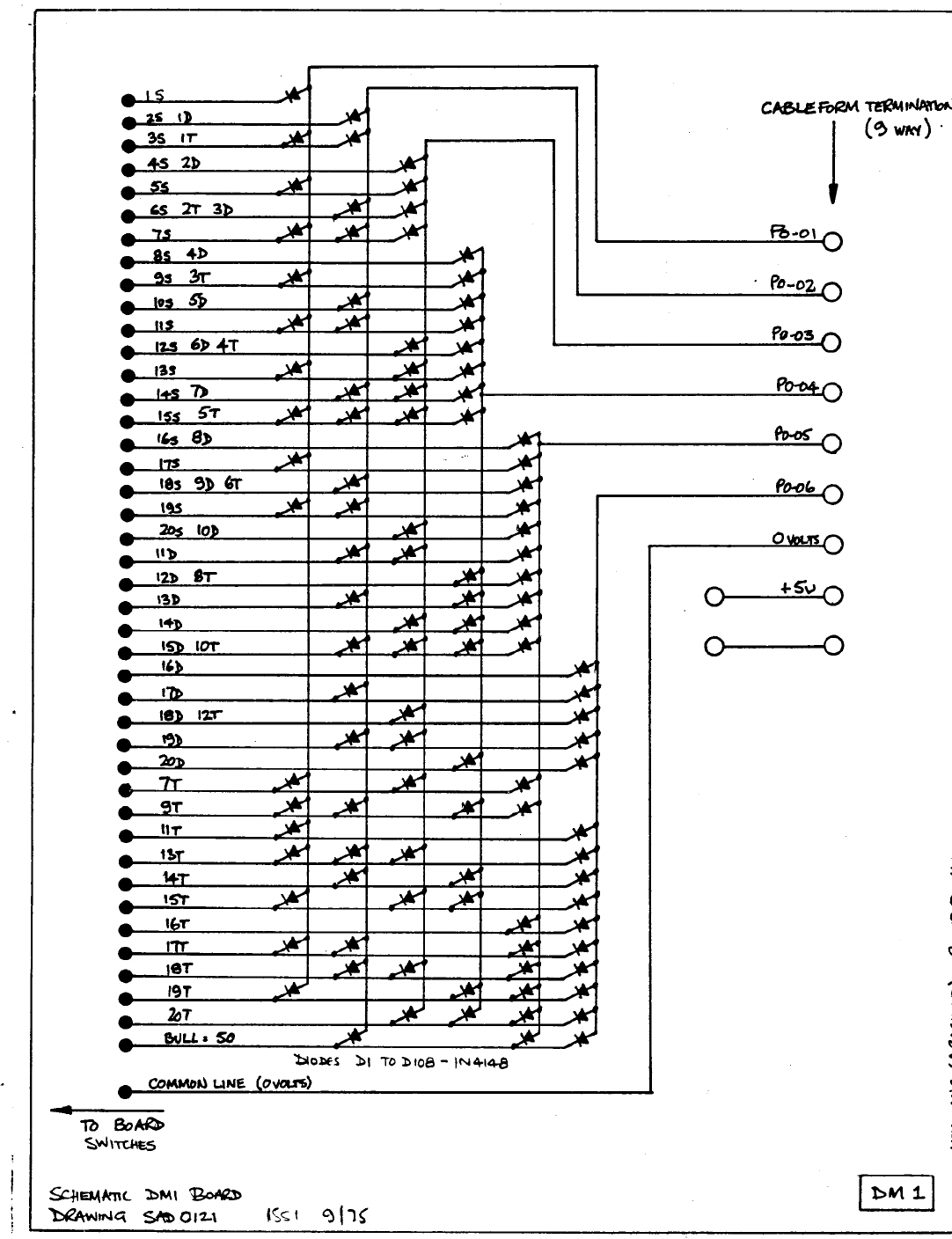
The wiring diagram, drawing SAD01 6, provides a schematic
representation of the wiring within the cabinet and also gives the
colours of the individual wires in the cableform.
The Component Parts List details all the major items in the
cabinets and from these two data sheets, the essential features
of this machine can be recognized.
All the low voltages used in this machine are derived from the
one transformer mounted in the base of the upper cabinet.
It has
been conservatively rated and is unlikely to fail. However if it is
necessary to check it, an A.C. voltmeter ought to give a 10 volt
reading between red/yellow lead and both of the yellow leads and
a 12 volt reading between the green/yellow lead and both of the
green leads.
3. Buzzer and Gong
The two devices are activated during the course of a game,
the buzzer to tell the player that he has gone beyond zero and the
gong to tell him that he has achieved zero.
The buzzer is driven from a
115V
A.C. signal and may need occasional
adjustment of the screw holding its mounting bracket to the
cabinet (the lower of the two screws) to obtain the loudest buzz.
The gong is driven from a 24V A.C. signal and has no'means of
adjustment.
3.3
Coin Mechanism
The need for regualr cleaning of this item is the same as for
coin mechanisms generally in vending machines. (Notes on this
are to be found in section 7). The optional resistor
Rl
of 100 ohm
shown on the cabinet wiring schedule (Drwing number SAD0126) prevents
the [machine from giving free games when the coin door is hit violently,
causing the microswitch to make a momentorary contact.