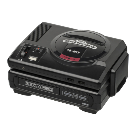
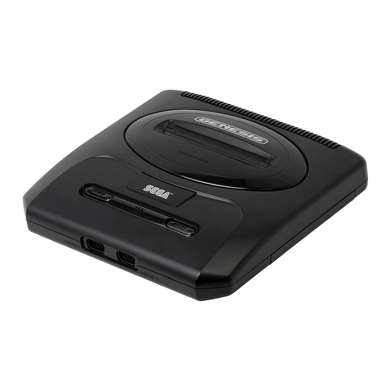
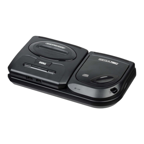
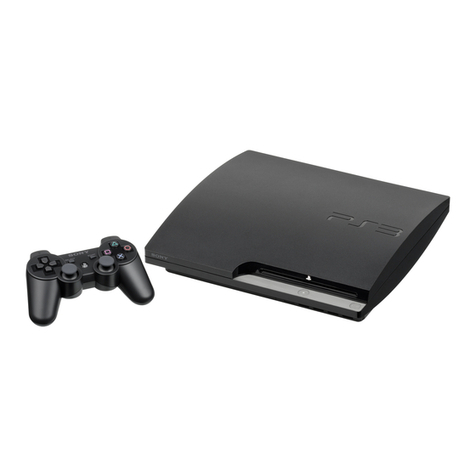
Sega genesis User manual


EPILEPSY WARNING
WARNING: READ BEFORE USING YOUR SEGA VIDEO GAME SYSTEM
Avery small percentage of individuals may experience epileptic seizures when
exposed to certain light patterns or flashing lights. Exposure to certain light patterns
or backgrounds on atelevision screen or while playing video games may induce an
epileptic seizure in these individuals. Certain conditions may induce undetected
epileptic symptoms even in persons who have no history of prior seizures or
epilepsy. If you, or anyone in your family, has an epileptic condition, consult your
physician prior to playing. If you experience any of the following symptoms while
playing avideo game: dizziness, altered vision, eye or muscle twitches, loss of
awareness, disorientation, any involuntary movement, or convulsions, IMMEDIATELY
discontinue use and consult your physician before resuming play.
GAME PLAY ASSISTANCE AND
INFORMATION
For expert game play assistance or
information on other great Sega
products, call the Sega experts at:
1-415-871-GAME
IF YOU NEED HELP
Read this manual thoroughly before
connecting your Genesis System. If you have
difficulties, first consult the Troubleshooting
Chart on page 18. For service, call the Sega
Consumer Service Department at:
1-800-USA-SEGA
Television Hookups
If your television hookup looks like this,
see page 6.
If your television hookup looks like this,
see page 7.
If your television hookup looks like this,
see page 8.
If your television hookup looks like this,
see page 9.
If your television hookup looks like this,
with aVCR attached, see page 10.
Single-Plug Antenna
F-Type Converter
UHF
VHF
Twin-Lead Antenna
UHF
VHF
i1
[CD ccn
Matching Transformer
UHF
i1
cCn tCn
VHF
VCR Connection
Optional Hookups
If your television has video and mono audio input jacks, you can use the optional Sega
Audio/Video Cable for improved graphics and sound. See page 11 for details.
If your television has video and stereo audio input jacks (Stereo TV), you can use the
optional Sega Stereo Audio/Video Cable for improved graphics and stereo sound. See
page 12 for details.
If you have aVCR which is attached to your stereo or stereo TV, see pages 11 to 13-
3

Contents
Identifying Parts 4
Connecting the Sega Genesis 5
Powering Up the System 14
Setting the TV Channel 14
Operating the System 15
Connecting this Genesis to aSega-CD 16
Troubleshooting Chart 18
Limited Warranty 19
Identifying Parts
SEGA GENESIS SYSTEM
CONSOLE
Cartridge Slot
Power Button
Directional Button
(D-Button)
Reset Button
Power-On Indicator
Control Port 2
Control Port 1
Start Button
Button C
Button B
Button A
GENESIS CONTROL PAD
RF Unit
i=L an
v
ANT IN A
TV OUT
SEGA RFUNiT
MODEL NO. MK- 1632
NTSC-M (VA) CH3-CH4
A/V IN CH SELECT
A4 3
4Hm >@
AC Adaptor
Precautions
When the AC Adaptor is not in use,
unplug it from the electrical outlet.
Do not leave the System or any of its
parts in direct sunlight, in damp areas
or near aheater.
Use only the Genesis AC Adaptor
supplied with this system. Using a
different AC Adaptor will damage your
System and void the warranty.
Do not disassemble the Console or
any of its parts.
Connecting the Sega Genesis
Hooking Up the Sega Genesis System Is Simple!
BACK VIEW OF CONSOLE
Reverse Side
AC Adaptor Jack
Extension Compartment
A/V OUT ADAPTOR
Connections to TV/Monitor and Antenna
There are various types of TV sets and antenna terminals. You may need to use all or
some of the three following types of connectors:
RF Unit
aw
"?A1
<NIM TVOUT
SEGA RFUNIT
MooeiNo.uK<i«32
NTSC-M fVA> CH3-CH4
AVW CHSELECT
^=OD
Matching Transformer
(75/300 ohm)
F-type Converter
(300/75 ohm)
•RF Unit (included)
•F-type Converter (300/75 ohm)
(not included)
•Matching Transformer (75/300 ohm)
(not included)
Compare your TV to the illustrations on
the next few pages to decide which
procedure is necessary.
5

If your TV does not have Video and Audio Inputs, use one of
the following procedures:
TV with single-plug Antenna Cable
(for either Cable TV or VHF Antenna Cable)
UHF
o5 £d
O)) VHF
B
\j BACK VIEW OF TV SET
U(VHF 75 ohm)
Cable TV or VHF Antenna Cable
(75 ohm) Antenna Cable
v
ANT IN A
TV OUT
SEGA™ RF UNIT
MODEL NO. MK- 1632
NTSC-M(VA)CH3-CH4
A/V IN CH SELECT
A«3
-? ?nnn U>>
RF UNIT
RF Cable
BACK VIEW OF CONSOLE P»
To A/V OUTJack
Ifasingle-plug Antenna Cable is plugged into your TV (or ifyou have Cable TV), use
the RF Unit. No other connectors are necessary.
pj~| Unplug the Antenna Cable from the TV, and plug it into the RF Unit.
Now, plug the RF Unit Antenna Cable into the TV.
|~3~| Finally, plug the RF Cable into the A/V OUTJack on the back of the Genesis
^™ Console.
aTo continue, see page 14.
TV with F-type Converter
UHF
VHF
F-1ype Converter (300/75 ohm)
BACK VIEW OF TV SET
(VHF 75 ohm)
£22.
~\
Antenna Cable
VA
ANT IN TV OUT
SEGA™ RF UNIT
MODEL NO. MK-1632
NTSC-M (VA) CH3-CH4
A/V IN CH SELECT
_A 1i-
RF Cable
RF UNIT [a
BACK VIEW OF CONSOLE
To A/V OUTJack
Ifan F-type Converter is plugged into your TV, use the RF Unit. No other connectors
are necessary.
Find the F-type Converter that's connected to the antenna and plugged into
the TV. Unplug it from the TV, and plug it into the RF Unit.
2~| Now, plug the RF Unit Antenna Cable into the TV.
a
rjlj Finally, plug the RF Cable into the A/V OUTJack on the back of the Genesis
^" Console.
H"! To continue, see page 14.
7

TV with an Antenna Cable
consisting of aTwin-Lead Antenna wire
Twin-Lead Antenna wire
---«.----|Q
UHF
VHF
F-type Converter (300/75 ohm)
(sold separately)
BACK VIEW OF TV SET (VHF 75 ohm)
Matching Transformer (75/300 ohm)
rs^ (sold separately)
cr Antenna Cable
CT2;
V
ANT IN A
TV OUT
SEGA'" RF UNIT
MODEL NO. MK- 1632
NTSC-M(VA)CH3-CH4
A/V IN CH SELECT
A43
*)) nnn .s.C
RF Cable
RF UNIT BACK VIEW OF CONSOLE
To A/V OUTjack
Ifthe Antenna Cable consists ofaTwin-Lead Antenna wire connected to your TV,
you'll need aMatching Transformer and an F-type Converter (both available from
electronics stores) and the RF Unit (included).
Disconnect the Twin-Lead Antenna wire from the TV, and connect it to the
F-type Converter.
aPlug the F-type Converter into the RF Unit.
I3|Plug the RF Unit Antenna Cable into the Matching Transformer. Connect the
^""" Transformer's Twin-Lead Antenna wire to the back of the TV.
I4|Finally, plug the RF Cable into the A/V OUTJack on the back of the Genesis
t™" Console.
aTo continue, see page 14.
8
TV with Cable TV or VHF Antenna Cable
plugged into Matching Transformer
Matching Transformer
(75/300 ohm)
UHF
VHF
_ _ mm ___ABACKVIEW OF TV SET
(VHF 75 ohm)
—
r
Antenna Cable
V A
ANT IN TV OUT
SEGA™ RF UNIT
MODEL NO. MK-1632
NTSC-M (VA) CH3-CH4
A/V IN CH SELECT
A43
(( ^T nnnTc l)
I 11111 r*p>
RF Cable
RF UNIT BACK VIEW OF CONSOLE
To A/V OUTJack
If Cable TVor aVHFAntenna Cable is already plugged into aMatching Transformer
on the back ofyour TV, use the RF Unit with your Matching Transformer.
Leave the Twin-Lead Antenna wire of the Matching Transformer connected
to the TV. Unplug the VHF Antenna Cable from the other end of the
Transformer.
aPlug the VHF Antenna Cable into the RF Unit.
rjlj Plug the RF Unit Antenna Cable into the Matching Transformer.
aFinally, plug the RF Cable into the A/V OUT Jack on the back of the Genesis
Console.
I5|To continue, see page 14.

TV with connected Video Cassette Recorder (VCR)
UHF
o5 £n
RFIn \J BACK VIEW OF TV SET (VHF 75 ohm)
Antenna Cable
RFOut
Video Cassette Recorder
A
TV OUT
V
ANT IN
SEGA" RF UNIT
MODEL NO. MK-1632
NTSC-M(VA)CH3-CH4
A/V IN CH SELECT
_A «i_ BACK VIEW OF CONSOLE
RF UNIT
RF Cable
a]
To A/V OUTJack
IfaVideo Cassette Recorder (VCR) is already connected between the antenna and the
television's VHF terminals, use the RF Unit (and, if necessary, an F-type Converter
and/or aMatching Transformer —both available from electronics stores).
Disconnect the VCR Cable from the television's VHF terminal (or from its
Matching Transformer). Then, plug this cable into the RF Unit. (If this cable
has aTwin-Lead Antenna wire, use an F-type Converter to make this
connection.)
aPlug the RF Unit Antenna Cable into the television's VHF terminal. (If a
Twin-Lead Antenna wire is required, use aMatching Transformer to make
this connection.)
Pjl Finally, plug the RF Cable into the A/V OUT Jack on the back of the Genesis
^™" Console.
4~| To continue, see page 14.
a
10
Optional Hookups
If your TV has video and audio inputs, use one of the following
procedures:
TV with Video and Mono Audio Input jacks, (or VCR, if TV is connected
to VCR)
f{ )) n n n Ui)
To A/V OUTjack
Yellow
White
Q> ((O
Video
Audio
To Monaural TV (or Monaural VCR)
Audio/Video Cable (sold separately)
If your TV has Video and Mono Audio Input Jacks (usually on the back of recent
models), you can use the optional Sega Audio/Video Cable for improved graphics
and sound. No other connectors are necessary.
If your TV is connected to your VCR, it is also possible to achieve improved graphics
and sound by using the optional Sega Audio/Video Cable with your VCR.
To order the Sega Audio/Video Cable, see the enclosed Parts Order Form and call
1-800-USA-SEGA, or contact your local retailer.
Insert the single-plug end of the Audio/Video Cable into the A/V OUTJack
on the Genesis Console,
["J"! Insert the yellow plug on the Audio/Video Cable into the composite TV or
^J monitor's Video Input Jack (or into the VCR Video Input Jack). Insert the
white plug into the TV or monitor's Audio Input Jack (or into the VCR Audio
Input Jack).
p3~| Lastly, select the Audio/Video Input setting on your TV (or VCR), when
^" playing the Genesis.
I4|To continue, see page 14.
77

TV with Video and Stereo Audio Input Jacks (Stereo TV), or TV
connected to Stereo VCR
U\T. —ana 1i )) Yellow
To A/VOUTJack
an
White
Red
To Stereo TV (or Stereo VCR)
Stereo Audio/Video Cable (sold separately)
If your TV has Video and Stereo Audio Input Jacks (Stereo TV) or is connected to a
Stereo VCR, you can use the optional Sega Stereo Audio/Video Cable for improved
graphics and stereo sound. No other connectors are necessary.
To order the Sega Stereo Audio/Video Cable, see the enclosed Parts Order Form
and call 1-800-USA-SEGA, or contact your local retailer.
Insert the single-plug end of the Stereo Audio/Video Cable into the A/V
OUT Jack on the Genesis Console.
aInsert the yellow plug on the Stereo Audio/Video Cable into the composite
TV or monitor's Video Input Jack (or into the VCR Video Input Jack). Insert
the white plug into the left Audio Input Jack, and the red plug into the right
Audio Input Jack of the TV or monitor (or VCR).
aLastly, select the Audio/Video Input setting on your TV (or VCR) when
playing the Genesis.
aTo continue, see page 14.
u
Stereo Sound for TV without Stereo Audio Input Jacks through aHome
Stereo or Stereo VCR
BACK VIEW OF COMPOSITE
TV OR MONITOR
(f \T nnn fr )) Yellow
To A/V OUTJack
White
o
Video
Red Female to Male
RCA Extension Cable
White
L......
Red
o
Audio (L)
Audio (R)
BACK VIEW OF STEREO OR VCR
If you have amono audio TV, you can still enjoy stereo sound from your Genesis
through your home stereo system or stereo VCR. Use the optional Sega Stereo
Audio/Video Cable for improved graphics and stereo sound. No other connectors
are necessary.
To order the Sega Stereo Audio/Video Cable, see the enclosed Parts Order Form
and call 1-800-USA-SEGA, or contact your local retailer.
Insert the single-plug end of the Stereo Audio/Video Cable into the A/V
OUT jack on the Genesis Console.
rn
a
Insert the yellow plug on the Stereo Audio/Video Cable into the composite
TV or monitor's Video Input Jack (or into the VCR Video Input Jack if the
VCR is connected to the stereo, and the TV is connected to the VCR).
Insert the red cable plug into the right Audio Input Jack, and the white plug
into the left Audio Input Jack of your stereo (or VCR). If your stereo is not
located very close to your TV, you may need an optional Female to Male
RCA Extension Cable.
Note: Always have the volume control turned all the way down when you
first turn on the Genesis System.
To continue, see page 14.
13

Powering Up the System
ACAdaptor
CD
To AC Adaptor Jack
Connect the AC Adaptor Plug to
the Adaptor Jack on the back of the
Genesis Console.
Plug the AC Adaptor into an
electrical outlet.
TV Channel Setting
RF UNIT
v
ANT IN A
TV OUT
SEGA™RF UNIT
MODELNO. MK-1632
NTSGM<VA)CH3-CH4
rA/V IN
ACH SELECT
43
i, zr
Side View
CHSELECTCH4-CH3
^Xc
>7 >
If you are using the RF Unit, set the Channel Switch on the RF Unit to CH 3
If you are not using the RF Unit, go to page 15.
a
Set your TV to channel 3.
If channel 3is used for TV viewing, set your TV to channel 4. Then, switch
the Channel Switch on the RF Unit to CH 4.
If your TV has an automatic fine-tuning control (AFC), turn it off and
manually adjust the picture. However, if you have acolor TV that turns
black and white when the AFC is turned off, leave the AFC on.
14
Operating the System
SEGA GENESIS SYSTEM
CONSOLE
Power Button
Directional Button
(D-Button)
GENESIS CONTROL PAD
Cartridge Slot
Game Cartridge (sold separately)
Reset Button
Power-On Indicator
Control Port 2
Control Port 1
Start Button
Button C
Button B
Button A
Plug aGenesis Control Pad into Control Port 1on the Console. For two
players, plug asecond Genesis Control Pad (optional) into Control Port 2.
r~2~|| Turn the Power Button off. Check it by making sure the Power-On Indicator
^" light is not on.
aInsert aCartridge, with the label facing forward, into the Cartridge Slot. Press
it FIRMLY into the Slot until the Cartridge "locks" into place. (If you turn the
Console over, the Cartridge should remain in place.)
4~b Turn the power on. The Power-On Indicator light should come on.
a
aIf all connections have been made properly, the Sega logo will appear,
followed by the game's title screen. In some cases, ademonstration game
will then begin (see the game's instruction manual).
15

Connecting this Genesis to aSega-CD
Note: Ifyour SEGA-CD looks like this, refer to
your SEGA-CD Owner's Manualfor details on
how to connect it to your Genesis.
Ifyour SEGA-CD looks like this, use these
instructions to connectyour Genesis and
SEGA-CD. CD
C3
()(1
CZD CZ2
Use the steel joining plate supplied with the original SEGA-CD to connect the
Genesis to the SEGA-CD. Follow the procedure below to attach the steel joining plate
to the Genesis. You'll need to use astandard screwdriver and aPhillips-head
screwdriver when attaching the steel joining plate.
•For details on thefunctions and operation ofthe SEGA-CD, please refer to the SEGA-
CD Owner's Manual.
Make sure your Genesis system is set
up and operating properly.
a
a
a
Turn off the power button of the
Genesis, and remove its AC adaptor
from the power outlet. (If the SEGA-CD
AC Adaptor is also plugged in, remove
it from the power outlet.)
Remove the five rubber pads on the
bottom of the Genesis with a
screwdriver or a similar tool.
(See illustration 1.)
Attach the small connector plate to the
bottom of the Genesis. The plate hooks
into position over the vents. (See
illustration 2.)
1&
111111111110 o
IIURIIIIII
—{OO h-O"
iimiiimrmrm
16
a
a
a
a
a
Screw
Steel Joining Plate
Remove the cover of the expansion slot
panel, located on the bottom of the
Genesis. Remove the red plastic cover
from the expansion slot connector
(ignore the labelled message "Do Not
Remove"). Store both covers in asafe
place. (See illustration 3.)
Position the steel joining plate on the
bottom of the Genesis, over the small
connector plate. Secure the steel joining
plate with the supplied screw.
(See illustration 4.)
Slide the Genesis onto the SEGA-CD.
Make sure the connector in the Genesis
expansion slot fits snugly into the
connector terminal on the SEGA-CD.
(See illustration 5.)
Make sure the Genesis power button is
turned off. Then plug in its AC adaptor.
(See illustration 6.)
Note: Always lift the Genesis and the
SEGA-CD together by holding onto the
sides of the SEGA-CD.
Plug the SEGA-CD's AC adaptor cable
into its jack on the back of the SEGA-
CD console. Then plug the adaptor
directly into an electrical outlet. Do not
use an extension cord. (See
illustration 6.)
Note: Do not switch the AC adaptors.
Use the Genesis AC Adaptor only with
the Genesis, and the SEGA-CD AC
Adaptor only with the SEGA-CD.
Stereo Sound
•For Stereo TV/Stereo VCR —use the Sega Stereo Audio Video Cable. See page 12.
•For Non-stereo TV —use the Sega Stereo Audio/Video Cable and Female to Male
RCA Extension Cable (see page 13) or the Sega Audio/Video Cable and Standard 2-pin
RCA Cable (see page 8of the Sega-CD Owner's Manual, CONNECTING ASTEREO TV).
17

Troubleshooting Chart
The Genesis System
Problem Before requesting repair, check the following items:
No picture on screen. •Is the Cartridge pushed FIRMLY into the Game Slot?
•Is the Genesis Console turned on?
•Is the AC Adaptor plugged in properly?
•Is the TV turned on?
•Is there power to the wall socket?
•Is the channel switch setting on the RF Unit the same
as the TV channel being used?
•Review the connections between the Antenna Cable,
Genesis Console, and TV terminals.
•If connecting through the VCR —is the VCR turned on?
•If connecting through the VCR —is the VCR set to
receive line input?
Screen flickers or
no color.
•Are the Antenna Cables connected properly?
•Are the TV channel fine adjustments set properly?
•Are the TV color controls set properly?
•Is the Genesis Cartridge inserted properly?
No game sound. •Is the TV volume too low, or off?
•Have the connection cables come loose, or gotten
disconnected?
Picture on TV screen
is unsteady.
•Adjust the vertical and horizontal hold controls on the
TV.
Fringes appear on TV
during agame.
•Adjust the manual fine-tuning adjustment controls on
the TV.
Fringes appear on TV
during abroadcast.
•Is the Antenna Cable connected properly?
•Make sure that you have turned off the Power Switch
on the Genesis Console.
No Power Light. •Is there power to the wall socket?
If you continue to have aproblem, use this manual to carefully re-connect the system,
step by step. If the problem still exists, please call the Sega Consumer Service j
Department, toll free, at 1-800-USA-SEGA.
18
Limited Warranty
Sega of America, Inc. warrants to the original con-
sumer purchaser that the Sega Genesis System and
all component parts shall be free from defects in
material and workmanship for aperiod of 90 days
from the date of purchase. If adefect covered by
this limited warranty occurs during the 90-day lim-
ited warranty period, Sega will repair or replace the
defective system or component part, at its option,
free of charge.
This limited warranty does not apply if the defects
have been caused by negligence, accident, unrea-
sonable use, modifications, tampering, or any other
causes not related to defective materials or work-
manship. Additionally, this warranty shall not be
valid if the serial number of the Genesis unit has
been altered, defaced or removed in any way.
Please retain your dated sales receipt to easily estab-
lish the date of purchase for in-warranty repairs.
To receive warranty service, call the Sega Consumer
Service Department at:
1-800-USA-SEGA
To receive Canadian warranty service, call the Sega
of Canada Consumer Service Department at:
1-800-872-7342
PLEASE CALL FIRST FOR REPAIR INFORMATION.
The cost of returning the system to Sega's Service
Center shall be paid by the purchaser.
DO NOT RETURN YOUR SEGA GENESIS SYSTEM
TO THE RETAIL SELLER.
Repairs after Expiration of Limited Warranty
If your Sega Genesis System requires repairs after
termination of the 90-day limited warranty period,
you may contact the Sega Consumer Service Depart-
ment at the number listed above. If the technician is
unable to solve the problem by phone, he or she
will advise you of the estimated cost of repair. If you
elect to have the repair done, you will need to re-
turn the defective merchandise, freight prepaid and
insured against loss or damage, to Sega's Service
Center with an enclosed check or money order pay-
able to Sega of America, Inc. for the amount of the
cost estimate provided to you by the technician. If,
after inspection, it is determined that your system
cannot be repaired, it will be returned to you and
your payment will be refunded.
Limitations on Warranty
Any applicable implied warranties, including warran-
ties of merchantability and fitness for aparticular
purpose, are hereby limited to 90 days from the
date of purchase and are subject to the conditions
set forth herein. In no event shall Sega of America,
Inc. be liable for consequential or incidental dam-
ages resulting from the breach of any express or
implied warranties.
The provisions of this limited warranty are valid in
the United States only. Some states do not allow
limitations on how long an implied warranty lasts
or exclusion of consequential or incidental dam-
ages, so the above limitation or exclusion may not
apply to you. This limited warranty provides you
with specific legal rights. You may have other
rights which vary from state to state.
Warning Statement
This equipment has been tested and found to com-
ply with the limits for aClass Bdigital device, pur-
suant to Part 15 of the FCC Rules. These limits are
designed to provide reasonable protection against
harmful interference in aresidential installation.
This equipment generates, uses and can radiate ra-
dio frequency energy and, if not installed and used
in accordance with the instructions, may cause
harmful interference to radio communications.
However, there is no guarantee that interference
will not occur in aparticular installation. If this
equipment does cause harmful interference to radio
or television reception, which can be determined
by turning the equipment off and on, the user is
encouraged to try to correct the interference by one
or more of the following measures;
Reorient or relocate the receiving antenna.
Increase the separation between the equip-
ment and the receiver.
Connect the equipment into an outlet on a
circuit different from that to which the re-
ceiver is connected.
Consult the dealer or an experienced radio/
TV technician for help.
Changes or modification not expressly approved by
Sega Enterprises Ltd., could void the user's author-
ity to operate the equipment.
Warning to owners of projection televisions:
Still pictures or images may cause perma-
nent picture-tube damage or mark the phos-
phor of the CRT. Avoid repeated or extended
use ofvideo games on large-screen projec-
tion televisions.
19
Other manuals for genesis
2
Table of contents
Other Sega Game Console manuals

Sega
Sega Dreamcxast User manual

Sega
Sega Game Gear VA1 User manual

Sega
Sega Master System User manual

Sega
Sega ROYAL RUMBLE 999-1117 Supplement

Sega
Sega Saturn User manual

Sega
Sega CD II User manual

Sega
Sega PODS User manual

Sega
Sega Master System I User manual

Sega
Sega Genesis 2 Supplement

Sega
Sega Mega CD2 User manual

Sega
Sega Zombie Revenge User manual

Sega
Sega Genesis Nomad MK-6100 User manual

Sega
Sega ScreenGopher User manual

Sega
Sega Master System User manual

Sega
Sega GENESIS FB8280C User manual

Sega
Sega SUBROC-3D User manual

Sega
Sega GENESIS II User manual

Sega
Sega Magical Truck Adventure User manual

Sega
Sega Saturn User manual

Sega
Sega Pico User manual