ARAG IBX 100 Quick start guide

INSTALLATION, USE AND MAINTENANCE
4679003.600
BOOM LEVELING KIT
Object Pool rel. 1.0.0

2
• LEGEND OF SYMBOLS
=Generic danger
=Warning
ECU =IBX100 remote control unit
VT =Virtual Terminal
OP =Object Pool
This manual is an integral part of the equipment to which it refers and must accompany the equipment in case of sale or change of ownership. Keep it for any
future reference; ARAG reserves the right to modify product specications and instructions at any moment and without notice.
WARNING:
THE NATIVE CONTROLS INSIDE YOUR VIRTUAL
TERMINAL HAVE THE PRIORITY ON ALL THE CONTROLS
DERIVING FROM THE IBX100. PLEASE, KEEP THIS IN
MIND WHEN PROGRAMMING AND USING THE PRODUCT.
LEGEND OF SYMBOLS

3
CONTENTS
1 Risks and protections before assembly............................................................................................................4
3 Intended use ........................................................................................................................................................4
4 Precautions ..........................................................................................................................................................4
6 Position on farming machine .............................................................................................................................5
6.1 System typical composition.........................................................................................................................5
8 Wiring connections .............................................................................................................................................9
8.1 General precautions for a correct harness position ....................................................................................9
8.2 IBX100 HYDRAULIC harness connection ..................................................................................................9
8.3 Ultrasonic sensors connection (boom leveling) ..........................................................................................9
9 Request of the blc function activation code ................................................................................................... 10
9.1 Menu > System status > Registration license ........................................................................................... 10
9.1.1 Activation procedure......................................................................................................................................10
10 Home ............................................................................................................................................................... 11
11 Control layout ....................................................................................................................................................12
12 Menu > Settings .................................................................................................................................................13
12.1 Menu > Settings > BLC.............................................................................................................................14
12.1.1 Menu > Settings > BLC > Headland boom height (HH)............................................................................... 14
12.1.2 Menu > Settings > BLC > Spraying boom height (HS)................................................................................ 14
12.1.3 Menu > Settings > BLC > Boom settings ..................................................................................................... 14
12.1.4 Menu > Settings > BLC > Sensor settings ................................................................................................... 15
12.1.5 Menu > Settings > BLC > BLC advanced .................................................................................................... 17
13 Menu > Alarms ...................................................................................................................................................19
14 Menu > Device status ........................................................................................................................................19
15 Use ...............................................................................................................................................................20
15.1 BLC - operation.........................................................................................................................................20
17 Technical data....................................................................................................................................................25
18 End-of-life disposal ...........................................................................................................................................25
19 Guarantee terms ................................................................................................................................................25
20 EU declaration of conformity............................................................................................................................25

4
INTRODUCTION
• MANUAL USE MODES
The section of this manual dedicated to the installation contains information for installers. For this reason we have used technical terms without
providing explanations which would be necessary for end users only.
THE INSTALLATION MUST BE CARRIED OUT BY AUTHORIZED AND SKILLED PERSONNEL ONLY. ARAG IS NOT RESPONSIBLE
FOR ANY OPERATION SPECIFIED IN THIS MANUAL CARRIED OUT BY UNAUTHORIZED OR UNSKILLED PERSONNEL.
• LIMITATIONS
The descriptions of the assembly phases refer to a "general" Virtual Terminal, so specic models will not be mentioned, unless a certain installation
procedure concerns exclusively one VT type.
• RESPONSIBILITY
The installer must carry out "workmanlike" installations and ensure to the end user the perfect operation of the whole system both with ARAG
components only and other brands' components.
ARAG always recommends using its components to install control systems.
The installer will be held responsible for any malfunction if he decides to use other brands' components even without actually changing the system
parts or harness.
The compatibility check with components and accessories of other manufacturers shall be carried out by the installer.
If the ARAG components installed together with other brands' components get damaged because of what stated above, no direct or indirect warranty
will be provided.
1 RISKS AND PROTECTIONS BEFORE ASSEMBLY
All installation works of IBX100 control unit, except the main connection (Refer to the manual supplied with IBX100 ISOBUS Hydraulic
- Chap. Settings > AUX conguration)must be done with battery disconnected, using suitable tools and any individual protection
equipment deemed necessary.
Use ONLY clean water for treatment tests and simulations: using chemicals during simulated treatment runs can seriously injure
persons in the vicinity.
DO NOT WORK NEAR THE BOOM WHILE THE BLC CONTROL SYSTEM IS IN OPERATION.
2 PRODUCT DESCRIPTION
The BLC kit is the system for boom leveling control (BLC) that allows keeping the sprayer arm parallel to the eld orientation and managing its distance
from the ground through the dedicated control unit - IBX100 hydraulic control unit- so as to ensure an even spraying covering.
Since the BLC control is an hydraulic function of the machine, an IBX100 Hydraulic ISOBUS control unit is required.
The control unit could be previously installed to control other hydraulic functions on the machine.
If you do not have any control unit, order separately an IBX100 hydraulic control unit and the relevant connection cable.
To enable IBX100 Hydraulic ISOBUS for the use of BLC, ask for the activation code to ARAG (“9.1.1 Activation procedure" on page 10).
3 INTENDED USE
The equipment you have purchased is a standard ISOBUS system compliant with ISO11783 to be applied to a crop spraying boom.
This device is designed to work on agricultural machinery for spraying and crop spraying applications.
The machine is designed and built in compliance with ISO 14982 standard (Electromagnetic compatibility - Forestry and farming
machines), harmonized with 2014/30/EU Directive.
4 PRECAUTIONS
• Do not aim water jets at the equipment.
• Do not use solvents or fuel to clean the case outer surface.
• Do not clean equipment with direct water jets.
• Comply with the specied power voltage (12 VDC).
• In case of voltaic arc welding, remove connectors from the device and disconnect the power cables.
• Only use ARAG genuine spare parts and accessories.
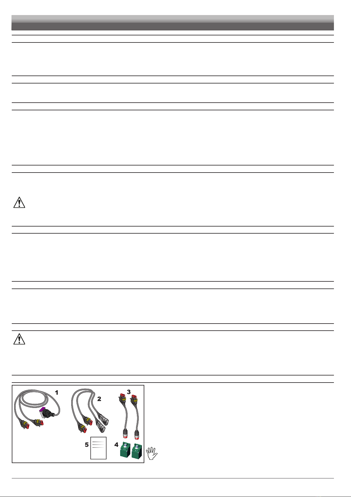
5 PACKAGE CONTENT
Fi g . 1
1Connection cable for sensors
2Extension for sensors - 5 m (no. 2)
3Adapter cables for ultrasonic sensors (no. 2)
4Ultrasonic sensors (no. 2)
5Purchase certication code
TO BE PURCHASED SEPARATELY:
• connection cable for IBX100 hydraulic control unit
TO BE PURCHASED SEPARATELY if not yet available on the existing system:
• IBX100 Hydraulic Isobus
• connection cable for hydraulic valves
• hydraulic valves for boom leveling
The kit supplied enables the BLC control function on an already existing system:
therefore, the mechanical and hydraulic components are supplied by the machine
manufacturer.

5
INSTALLATION
6 POSITION ON FARMING MACHINE
6.1 System typical composition
WARNING: DO NOT CONNECT ISOBUS CONNECTOR.
THIS CONNECTION WILL HAVE TO BE PERFORMED ONLY AT A LATER STAGE, ONCE ALL COMPONENTS HAVE BEEN
INSTALLED (Refer to the manual supplied with IBX100 ISOBUS Hydraulic - Chap. System typical composition).
To connect all parts of the system correctly, make sure to use the proper connection cables.
Consider any variants depending on system type.
PART NO. 4679005
Fi g . 2
Legend of connection cables:
1Connection cable for ultrasonic sensors
2Extensions for ultrasonic sensors
3Adapter cables for ultrasonic sensors
4Ultrasonic sensors

6
Crop
7 INSTALLATION OF ULTRASOUND SENSORS
It is the installer responsibility to check that all indications described are complied with.
Precautions to follow for a long-lasting installation:
• Fix the sensor to a strong structure.
• Protect sensor body and connector with a guard.
• Keep sensor sensitive surface clean.
• Clean only with a soft wet cloth.
• Do not use aggressive detergents or products.
• Do not clean equipment with direct water jets.
Fi g . 3
Yellow LED Yellow LED Green LED
Green
LED
CONNECTOR
Not connected
+ 12 V
GND
PIN
M12x1, 5-pin
Not connected
Analogue output
POSITION COLOR CONNECTION
1Brown + 12 V
2-- Not connected
3Blue GND
4Black Analogue output
5-- Not connected
Fi g . 4
Driving direction
(FORWARD)
INSTALLATION ORIENTATION
Connector
Sensitive at
surface
Fixing holes
For a correct operation, respect the installation direction (Fi g . 4 ).
INSTALLATION
WARNING: CONNECTOR PINOUT IS PROVIDED ONLY TO MAKE ANY SYSTEM
DIAGNOSIS EASIER FOR TECHNICIANS / INSTALLERS.
THE ULTRASONIC SENSORS MUST NOT BE MODIFIED AND/OR
REPLACED WITH DIFFERENT TYPES OF SENSORS SINCE THEY COULD
CAUSE FIRES OR DAMAGE THE BOOM.

7
7.1 Sensor correct identication and positioning
Two types of layouts are available:
• BASIC SETUP - with a pair of sensors US1 + US2 (Fi g . 5 ).
Fi g . 5
Place the sensors in relation to the boom center C:
US1 (RH side) + US2 (LH side) = external pair of sensors (far from boom center), at a distance from boom end corresponding
approximately to 30% of the half-boom length.
• COMPLETE SETUP - with two pairs of sensors US1 + US2 and US3 + US4 (F i g. 6 ).
Fi g . 6
Place the sensors in relation to the boom center C:
US1 (RH side) + US2 (LH side) = external pair of sensors (far from boom center), refer to basic setup.
US3 + US4 = internal pair of sensors (the ones closest to boom center), at a distance from boom center corresponding to
approximately 30% of the half-boom length.
Install the US1 / US3 sensors on the LH side of the boom and the US2 / US4 sensors on the RH side (rear view of the tractor).
The conguration with two pairs of sensors is to be preferred: in case of very large booms, it allows creating an average of the
distances of sensors from ground unevennesses.
Furthermore, the sensitive surface of the sensors must be positioned ALWAYS HIGHER than nozzle outlet (LV > 0 mm, F i g. 7 ).
SENSITIVE SURFACE
OF THE SENSOR
OUTLET
OF THE NOZZLES
Fi g . 7
CHECK THAT SENSORS ARE CONNECTED TO THE CORRESPONDING CONNECTORS AS PER THE MARKING INDICATED IN
PAR. 8.3 ULTRASONIC SENSORS CONNECTION (BOOM LEVELING).
THE SYSTEM COULD NOT BE ACKNOWLEDGED OR BE ABLE TO OPERATE WITH DIFFERENT CONNECTIONS.
INSTALLATION

8
INSTALLATION
7.2 Sensor optimal orientation
Fi g . 8
• Lateral inclination (internal)
Sensors must be oriented towards the nearest side of the tractor;
an inclination of 5° is recommended and useful to compensate the gradient of the boom
due to the BLC system correction.
Fi g . 9
• Forward inclination / height
As the ultrasound emission of the sensor has a conical shape with an amplitude of
approx. 15°, advance the sensors by 15° with respect to the tractor travel direction.
This inclination allows avoiding interferences with the cone outlet of the liquid sprayed
by the nozzles.
To optimize the sensor measuring capacity it might be also useful to move the sensor
position forward (always in relation to the travel direction) and / or increase their height
with respect to the nozzle outlet.
ALWAYS avoid the range of action of the sensor to superimpose the spraying cone.
Fi g . 10
• Minimum distance between the sensors
If the sensors are too close to one another ultrasound superimpositions may occur
causing system errors: respect the minimum distance of 2.5 m.
It is the installer responsibility to check that the measurements detected by the sensors are correct and to avoid possible
interferences with the cone outlet of the liquid sprayed by the nozzles.

9
INSTALLATION
8 WIRING CONNECTIONS
• Use original ARAG harnesses only.
• Take care not to break, pull, tear or cut the cables.
• Use of unsuitable cables not provided by ARAG automatically voids the warranty.
• ARAG is not liable for any damage to the equipment, persons or animals caused by failure to observe the above instructions.
8.1 General precautions for a correct harness position
• Securing the cables:
- secure the harness so that it does not interfere with moving parts;
- route the harnesses so that they cannot be damaged or broken by machine movements or twisting.
• Routing the cables to protect against water inltrations:
- the cable branches must ALWAYS be facing down.
• Fitting the cables to the connection points:
- Do not force the connectors by pushing too hard or bending them: the contacts may be damaged and system operation may be compromised.
Use ONLY the cables and accessories indicated in the ARAG catalog, having technical features suitable for the use to be made
of them.
8.2 IBX100 HYDRAULIC harness connection
Fi g . 11
NUM CONNECTION POINTS
1Ultrasonic sensors (boom leveling)
2Hydraulic unit
3VT / IBX100 Sprayer ISOBUS
8.3 Ultrasonic sensors connection (boom leveling)
CONNECTOR CONNECTION
REF. CABLE 1 - Fig. 2 on page 5
Close the unused connectors with the relevant caps supplied in the package.
US1 ÷ US4 Ultrasonic sensor 1 ÷ 4
US5 NOT CONNECTED
AUX NOT CONNECTED

10
INSTALLATION
9 REQUEST OF THE BLC FUNCTION ACTIVATION CODE
9.1 Menu > System status > Registration license
To activate the BLC function on the control unit, AN ACTIVATION CODE IS REQUIRED.
Ask the code to ARAG, by providing the following information:
- purchase identication code received with the kit.
- hydraulic control unit serial number ("SERIAL NO." label on control unit rear side) that can be viewed also from the Device status menu
of the monitor in the example:
Menu > System status
9.1.1 Activation procedure
2
1
Fi g . 1 2
1 Enter the supplied code and conrm.
The IBX100 will restart.
- Once nished, the activated function will be displayed by the system.
- Now the control unit is active: monitor shows all the menus for BLC control setup
and use
2Active functions.
WARNING
AFTER CONTROL UNIT ACTIVATION, PROGRAM THE NECESSARY PARAMETERS (par. 10.2 and 10.3, shown in Fig. 15).

11
HOME
10 HOME
The main screen varies based on the active functions.
Boom rotation displaying:
Clockwise rotation
Boom lifting displaying
Boom lowering displaying
Automatic/Manual activation button par. 14.2
Boom rotation displaying:
Counter-clockwise rotation
Boom height during
spraying HS par.
12.1.2
Auxiliary Input ON/OFF
Increases boom height (
HH
or
HS
based on
the highlighted function):
+ 0.10 m at every button pressure
Decreases boom height (
HH
or
HS
based on
the highlighted function):
- 0.10 m at every button pressure
Boom Leveling Control AUTO activation control par. 14.2).
Active alarm Chap. 13
Detection type selection button.
HS HH
- Boom height during spraying HS par.
12.1.2
- Headland boom height HH par. 12.1.1
Headland boom height HH par. 12.1.1
Fi g . 1 3

12
USING THE KEYS
11 CONTROL LAYOUT
Goes to menu screen
Goes back by one screen
Goes back to HOME
Goes to the following page
Goes back to the previous page
ENTERING A NUMERICAL VALUE
Icons are given as a reference as they can vary depending on the Virtual Terminal used:
Deletes
Exits
Conrms
Before system setup, check:
• that all components are correctly installed;
• the correct connection to the power source;
• the component connection.
Failure to correctly connect system components or to use specied components might damage the device or its components.
Upon rst switching on, enter the device basic settings.
ONCE ALL MODIFICATIONS HAVE BEEN COMPLETED, UPON QUITTING THE CURRENT PAGE,THE SYSTEM WILL PERFORM AN
AUTOMATIC SAVING

13
SETTINGS
12 MENU > SETTINGS
Fi g . 1 4
Allows setting the BLC parameters
Fig. 15
CONTINUES > > >

14
SETTINGS
12.1 Menu > Settings > BLC
Fig. 16
Allows accessing the BLC setup pages.
12.1.1 Menu > Settings > BLC > Headland boom height (HH)
Distance between the boom and the crop in presence of obstacles or during tractor maneuvering phases. We will call these areas "HEADLAND".
Activating the AUTOMATIC control (AUTO par. 15.4), the BLC system will carry out the corrections required to take the boom at this height, BUT ONLY
AFTER A SPECIFIC COMMAND BY THE OPERATOR, which is preset in the Auxiliary Input or through VT (par. 14.2).
By editing the height values during the AUTO control, THE SYSTEM ACTIVATES THE MANUAL CONTROL for safety reasons.
Once the modications have been completed, re-activate the AUTO control (par. 15.4).
12.1.2 Menu > Settings > BLC > Spraying boom height (HS)
Distance between the boom and the crop DURING SPRAYING.
Activating the AUTOMATIC control (AUTO par. 15.4), the BLC system will carry out the corrections required to keep the boom at this height.
By editing the height values during the AUTO control, THE SYSTEM ACTIVATES THE MANUAL CONTROL for safety reasons.
Once the modications have been completed, re-activate the AUTO control (par. 15.4).
12.1.3 Menu > Settings > BLC > Boom settings
1
2
Fi g . 1 7
1Enter boom length value.
2It allows enabling the number of sensors present inside the system installed on the
farming machine (par. 12.1.4).
CONTINUES > > >

15
12.1.4 Menu > Settings > BLC > Sensor settings
SYSTEM WITH 2 SENSORS
Fig. 18
Fig. 19
Number of sensors: 2(US1 + US2).
Number of ultrasonic sensors used by the BLC control.
EXTERNAL SENSORS
Fig. 20
External sensor posit. x1: indicates the distance between center C(point
zero) and US1 sensor. The value must be negative (Fig. 21).
External sensor posit. y1: indicates the LV distance between the sensitive
surface of sensor US1 and the outlet of the nozzles (Fig. 22).
The sensitive surface must be positioned ALWAYS HIGHER than the outlet
(LV > 0 mm).
External sensor posit. x2: indicates the distance between center C(point
zero) and US2 sensor. The value must be positive (Fig. 21).
External sensor posit. y2: indicates the LV distance between the sensitive
surface of sensor US2 and the outlet of the nozzles (Fig. 22).
The sensitive surface must be positioned ALWAYS HIGHER than the outlet
(LV > 0 mm).
Fig. 21
SENSITIVE SURFACE
OF THE SENSOR
OUTLET
OF THE NOZZLES
Fig. 22
SETTINGS

16
SETTINGS
SYSTEM WITH 4 SENSORS
Fig. 23
Fig. 24
Number of sensors: 4(US1 + US2 and US3 + US4).
Number of ultrasonic sensors used by the BLC control.
EXTERNAL SENSORS INTERNAL SENSORS
Fig. 25 Fig. 26
EXTERNAL SENSORS - Sensor settings 2/3
See previous page.
INTERNAL SENSORS - Sensor settings 3/3
Internal sensor posit. x3: indicates the distance between center C(point zero) and US3 sensor. The value must be negative (Fig. 21).
Internal sensor posit. y3: indicates the LV distance between the sensitive surface of sensor US3 and the outlet of the nozzles (Fig. 22).
The sensitive surface must be positioned ALWAYS HIGHER than the outlet (LV > 0 mm).
Internal sensor posit. x4: indicates the distance between center C(point zero) and US4 sensor. The value must be positive (Fig. 21).
Internal sensor posit. y4: indicates the LV distance between the sensitive surface of sensor US4 and the outlet of the nozzles (Fig. 22).
The sensitive surface must be positioned ALWAYS HIGHER than the outlet (LV > 0 mm).
Fig. 27
SENSITIVE SURFACE
OF THE SENSOR
OUTLET
OF THE NOZZLES
Fig. 28

17
SETTINGS
12.1.5 Menu > Settings > BLC > BLC advanced
Fig. 29
This menu allows entering the boom dynamic characteristics.
All parameters are explained in detail in the following pages.
The values must be detected directly on the machine because strictly linked to the hydraulic / mechanical system of the
machine.
DURING MEASURING PROCEDURES, MOVE THE BOOM ALONG THE MAXIMUM ALLOWABLE DISTANCE, COMPATIBLY WITH
THE MACHINE MECHANICAL CHARACTERISTICS AND DIMENSIONS.
Height aggressiveness - BOOM HEIGHT CONTROL AGGRESSIVENESS
It adjusts the power applied by the BLC control to lift / lower the boom.
The easiest way to adjust the aggressiveness value is to check for the presence of swingings during boom movement - from maximum to minimum height.
Too high or too low values make the control unstable and cause vibrations; adjust the aggressiveness value until reaching a smooth implement control
without jerks.
Carry out this procedure with the BOOM COMPLETELY OPEN:
1Check that the boom is perfectly horizontal to the ground.
2 Set the spraying height to the minimum value (Spraying boom height menu, par.
12.1.2 on page 14
).
3Bring the rotation speed of the power take-off to the typical operating value.
4Disable the BLC control: activate the MANUAL mode (par. 14.2).
5Set an aggressiveness value (Fig. 29).
6Bring the boom to the maximum height (activate the lifting switch on the hydraulic control panel / VT / Joystick).
7Enable the BLC control: activate the AUTOMATIC mode (par. 14.2).
The boom will move automatically to reach the spraying height:
• If boom movement is too slow and with jerks, the aggressiveness level is too low.
Repeat the procedure from point 4, increasing the value.
• If the boom moves too quickly and swinging the aggressiveness level is too high.
As before, repeat the procedure from point 4, decreasing the value.
The ideal adjustment is obtained when boom movement is smooth, without jerks.
CONTINUES > > >

18
SETTINGS
The values must be detected directly on the machine because strictly linked to the hydraulic / mechanical system of the machine.
DURING MEASURING PROCEDURES, MOVE THE BOOM ALONG THE MAXIMUM ALLOWABLE DISTANCE, COMPATIBLY WITH
THE MACHINE MECHANICAL CHARACTERISTICS AND DIMENSIONS.
Tilt aggressiveness - BOOM LEVELING CONTROL AGGRESSIVENESS
It adjusts the power applied by the BLC control to rotate the boom.
The easiest way to adjust the aggressiveness value is to check for swingings during boom rotation.
Too high or too low values make the control unstable and cause vibrations; adjust the aggressiveness value until reaching a smooth implement control
without jerks.
Carry out this procedure with the BOOM COMPLETELY OPEN:
1 Set the boom rotation center Cto maximum height.
2Bring the rotation speed of the power take-off to the typical operating value.
3Disable the BLC control: activate the MANUAL mode (par. 14.2).
4Set an aggressiveness value (Fig. 29).
5Bring the boom LH end to the minimum height (activate the lifting switch on the hydraulic control panel / VT / Joystick).
6Enable the BLC control: activate the AUTOMATIC mode (par. 14.2).
The boom will rotate automatically to reach the horizontal position:
• If boom movement is too slow and with jerks, the aggressiveness level is too low.
Repeat the procedure from point 3, increasing the value.
• If the boom moves too quickly and swinging the aggressiveness level is too high.
As before, repeat the procedure from point 3, decreasing the value.
The ideal adjustment is obtained when boom movement is smooth, without jerks.
The Tilt aggressiveness parameter works in combination with the following Tilt speed damping parameter:
if aggressiveness setup is not as desired, increase the gain and repeat the adjustment.
Height error gain - PROPORTIONAL GAIN ON BOOM HEIGHT CONTROL
This parameter works in combination with the aggressiveness of the boom height control.
It reduces the error between the set spraying height and the one effectively reached with the BLC system.
Before entering the gain factor, set the aggressiveness (menu Height aggressiveness par. 12.1.5 on page 17).
The easiest way to determine the value is to check the boom height after the BLC system has completed the correction; adjust the gain, if necessary.
Carry out this procedure with the BOOM COMPLETELY OPEN:
1Check that the boom is perfectly horizontal to the ground.
2 Set the spraying height to the minimum value (Spraying boom height menu, par.
12.1.2 on page 14
).
3Bring the rotation speed of the power take-off to the typical operating value.
4Disable the BLC control: activate the MANUAL mode (par. 14.2).
5Bring the boom to the maximum height (activate the lifting switch on the hydraulic control panel / VT / Joystick).
6Set a gain value (Fig. 29).
7Enable the BLC control: activate the AUTOMATIC mode (par. 14.2).
The boom will move automatically to reach the spraying height.
Check the height reached:
• If the boom has exceeded the set height, repeat the procedure from point 4, decreasing the value.
• If the boom has not reached the set height, repeat the procedure from point 4, increasing the value.
Now, if the boom lifting control exceeds the set height, lower the aggressiveness and repeat the procedure relevant to the gain.
Tilt speed damping: - DAMPING ON BOOM ROTATION CONTROL
This parameter works in combination with the aggressiveness of the boom leveling control.
It allows the BLC system to rotate the boom without swingings or position errors.
Before entering the damping factor, set the aggressiveness (menu Tilt aggressiveness Fig. 29):
if the setup of Tilt aggressiveness is not carried out properly increase the value (Fig. 29).

19
13 MENU > ALARMS
This screen summarizes the alarm notications active for the operators.
Fig. 30 Fig. 31
For the procedure to be followed when an alarm occurs, please refer to par. 16.1.
14 MENU > DEVICE STATUS
This screen shows the status of the set and installed sensors.
The display will show the current sensor reading.
Fig. 32 Fig. 33
ALARMS - DEVICE STATUS

20
USE
15 USE
15.1 BLC - OPERATION
15.2 Fixed geometry
The BLC control considers the boom as a single body: it is then a xed geometry control as the division at boom section is negligible. The boom
must be COMPLETELY open.
To the keep the boom in the desired position, the BLC control performs two types of independent corrections at the same time:
• Boom leveling
The boom rotates with respect to the center (Cin Fig. 34) of the mechanical arm, leveling the inclination with respect to the crop.
1Counter-clockwise rotation (orange - CCW),
2Clockwise rotation (yellow - CW),
• Boom height control
The boom moves vertically controlling the height ( L, C and Rin Fig. 34) with respect to the crop.
3Lifting (blue - UP)
4Lowering (light blue - DOWN),
The ultrasonic sensors (US1÷US4 in Fig. 34) installed on the boom provide the data required for the correction, determining the distances
L/ C/ Rfrom boom to crop.
Fig. 34
WARNING
• Ultrasonic sensors do not distinguish between crop and soil as they detect the rst object encountered.
Boom height is the distance between the arm and the crop (when present).
• The boom, during leveling, rotates with respect to the boom instantaneous center of rotation (CPOINT).
15.3 Hydraulic control
Thanks to the IBX100 hydraulic control unit the BLC control automatically activates:
• the leveling and boom height control hydraulic functions
• system hydraulic drain valve (pilot valve)
Check that the hydraulic system and the valves are connected to the IBX100 hydraulic control unit.
WARNING: DURING AUTOMATIC LEVELING, THE SYSTEM ACTIVATES THE PILOT VALVE, HENCE THE HYDRAULIC CIRCUIT IS
PRESSURIZED.
OTHER HYDRAULIC FUNCTIONS (MOVEMENTS, DRIVES, ETC...) CONNECTED TO THE SAME SYSTEM CAN BE ACTIVATED BY
SENDING THE CONTROL ONLY TO THE SUITABLE VALVE, SINCE THE PILOT VALVE IS ALREADY ACTIVATED BY THE BLC. MAKE
SURE THAT THIS DOES NOT JEOPARDIZE MACHINE SAFETY.
Table of contents
Popular Industrial Electrical manuals by other brands

Murata
Murata GRM188R61A824KA61 Series Reference sheet

Bartec
Bartec DTL III Ex operating manual

nvent
nvent TR-400A instruction sheet

Command access
Command access VLP-UL-M-KIT installation instructions

Murata
Murata GRM033C80J683ME84 Series Reference sheet

Murata
Murata GRM188R71H472JA01 Series Reference sheet

Murata
Murata GQM22M5C2H4R0BB01 Series Reference sheet

Murata
Murata GRM0335C1H910JA01 Series Reference sheet

Murata
Murata GRM219R71E105KA88 Series Reference sheet

WEG
WEG PFW03-M8 Configuration guide

Murata
Murata GRM31CR72A105MA01 Series Reference sheet

Murata
Murata GRM219R71E473KA01 Series Reference sheet