arbane APG DA User manual

DA
User Guide

User Guide - DA amplifiers
01/2022DOP_1502_A 2
General information
DA amplifier - User Guide
01/2022 EN
APG France (Active Audio / Arbane Groupe)
8 Rue Johannes Gutenberg - 44340 Bouguenais- France
Tél : 02.40.46.66.64
www.apg.audio/en


User Guide - DA amplifiers
01/2022DOP_1502_A 4

User Guide - DA amplifiers
01/2022DOP_1502_A 5
Important Safety Instructions
Common symbols and meanings
• THE TRIANGLE WITH THE LIGHTNING BOLT IS USED TO ALERT THE USER TO THE RISK OF
ELECTRIC SHOCK.
• THE TRIANGLE WITH THE EXCLAMATION POINT IS USED TO ALERT THE USER TO IMPORTANT
OPERATING OR MAINTENANCE INSTRUCTIONS.
• THE CE-MARK INDICATES THE COMPLIANCE OF THE PRODUCT TO ALL THE APPLICABLE
EUROPEAN DIRECTIVES
• SYMBOL FOR EARTH/GROUND CONNECTION.
• SYMBOL INDICATING THAT THE EQUIPMENT IS FOR INDOOR USE ONLY.
• SYMBOL FOR CONFORMITY WITH DIRECTIVE 2012/19/EC OF THE EUROPEAN PARLIAMENT
ON WASTE ELECTRICAL AND ELECTRONIC EQUIPMENT (WEEE).
Safety Warnings
• OPERATING TEMPERATURE RANGE: 0°C TO +50°C - DERATING ABOVE 35°C.
• STORAGE RELATIVE HUMIDITY RANGE: 10% TO 90% HUMIDITY (NON CONDENSING).
• DO NOT USE THE UNIT AT ALTITUDES ABOVE 2000 M.
• DO NOT USE THE UNIT IN TROPICAL ENVIRONMENT.
• TO REDUCE THE RISK OF ELECTRIC SHOCK, DO NOT ATTEMPT TO OPEN ANY PART OF THE
UNIT. NO USER-SERVICEABLE PARTS INSIDE. REFER SERVICING TO QUALIFIED SERVICE
PERSONNEL.
• CONNECTION TO THE MAINS SHALL BE DONE ONLY BY A ELECTROTECHNICAL SKILLED
PERSON ACCORDING THE NATIONAL REQUIREMENTS OF THE COUNTRIES WHERE THE UNIT
IS SOLD.
• DO NOT USE THIS AMPLIFIER IF THE ELECTRICAL POWER CORD IS FRAYED OR BROKEN.
• TO AVOID ELECTRICAL SHOCK, DO NOT TOUCH ANY EXPOSED SPEAKER WIRING WHILE THE
AMPLIFIER IS OPERATING.
• DO NOT SPILL WATER OR OTHER LIQUIDS INTO OR ON THE AMPLIFIER.
• THIS DEVICE MUST BE POWERED EXCLUSIVELY BY EARTH CONNECTED MAINS SOCKETS IN
ELECTRICAL NETWORKS COMPLIANT TO THE IEC 364 OR SIMILAR RULES
• DISCONNECT THE AC MAINS SOURCE BEFORE ATTEMPTING TO CLEAN ANY PART OF THE
AMPLIFIER
• POWERSOFT SUGGESTS TO PLUG THE DA SERIES TO A 16 A RATING, C OR D CURVE, 10 kA
SECTIONING BREAKER.

User Guide - DA amplifiers
01/2022DOP_1502_A 6
• OUTPUT TERMINALS ARE HAZARDOUS: WIRING CONNECTION TO THESE TERMINALS
REQUIRES INSTALLATION BY AN INSTRUCTED PERSON AND THE USE OF READY MADE
LEADS.
• PROPERLY FIT THE AC MAINS PLUG TO THE AMPLIFIER INLET. BEFORE POWERING THIS
AMPLIFIER, VERIFY THAT THE CORRECT VOLTAGE RATING IS BEING USED.
• TAKE CARE TO LOCK THE OUTPUT TERMINAL BEFORE SWITCHING THE DEVICE ON.
• VERIFY THAT YOUR MAINS CONNECTION IS CAPABLE OF SATISFYING THE POWER
RATINGS OF THE DEVICE
• NO NAKED FLAME SOURCES SUCH AS LIGHTED CANDLES SHOULD BE PLACED ON THE
AMPLIFIER.
• TO PREVENT INJURY, THIS APPARATUS MUST BE SECURELY RACK MOUNTED IN
ACCORDANCE WITH THE INSTALLATION INSTRUCTIONS.
• THIS EQUIPMENT SHALL BE MOUNTED AT A MAXIMUM HEIGHT OF 2 M
• THE MANUFACTURER CANNOT BE HELD RESPONSIBLE FOR DAMAGES CAUSED TO
PERSONS, THINGS OR DATA DUE TO AN IMPROPER OR MISSING GROUND CONNECTION.
• IT IS ABSOLUTELY NECESSARY TO VERIFY THESE FUNDAMENTAL REQUIREMENTS
OF SAFETY AND, IN CASE OF DOUBT, REQUIRE AN ACCURATE CHECK BY QUALIFIED
PERSONNEL.

User Guide - DA amplifiers
01/2022DOP_1502_A 7
Please read and keep all safety and use instructions.
This product is intended for installation by professional installers only! This
document is intended to provide professional installers with basic installation and safety guidelines for this product in typical
fixed-installation systems. Please read this document and all safety warnings before attempting installation.
1. Read these instructions.
2. Keep these instructions.
3. Heed all warnings.
4. Follow all instructions.
5. Do not use this equipment near water.
6. Clean only with a dry cloth.
7. Do not block any ventilation openings. Install in accordance with the manufacturer’s instructions.
8. Do not install near any heat sources such as radiators, heat registers, stoves, or other apparatus that produce heat.
9. Do not defeat the safety purpose of the polarized or grounding-type plug. A polarized plug has two blades with one
wider than the other. A groundingtype plug has two blades and a third grounding prong. The wide blade or the third prong
are provided for your safety. If the provided plug does not fit into your outlet, consult an electrician for replacement of the
obsolete outlet.
10. Protect the power cord from being walked on or pinched particularly at plugs, convenience receptacles, and the point
where they exit from the apparatus.
11. Only use attachments/accessories specified by the manufacturer.
12. Use only with the cart, stand, tripod, bracket, or table specified by the manufacturer, or sold with the apparatus. When a
cart isused, use caution when moving the cart/apparatus combination to avoid injury from tip-over.
13. Unplug this apparatus during lightning storms or when unused for long periods of time.
14. Refer all servicing to qualified service personnel. Servicing is required when the apparatus has been damaged in any
way, such as power-supply cord or plug is damaged, liquid has been spilled or objects have fallen into the apparatus, the
apparatus has been exposed to rain or moisture, does not operate normally, or has been dropped.

User Guide - DA amplifiers
01/2022DOP_1502_A 8
Regulatory Compliance Statements
Europe
If the time arises to dispose of your product, please recycle all possible component.
This symbol indicates that when the end-user wishes to discard this product, it must be sent to separate
collection facilities for recovery and recycling. By separating this product from other household-type waste, the
volume of waste sent to incinerators or land-fills will be reduced and natural resources
will thus be conserved.
The Waste Electrical and Electronic Equipment Directive (WEEE Directive) aims to minimise the impact of electrical and
electronic goods on the environment. Powersoft S.p.A. comply with the Directive 2012/19/EU of the European Parliament on
waste electrical finance the cost of treatment and recovery of electronic equipment (WEEE) in order to reduce the amount of
WEEE that is being disposed of in land-fill site. All of our products are marked with the WEEE symbol; this indicates that this
product must NOT be disposed of with other waste. Instead it is the user’s responsibility to dispose of their waste electrical and
electronic equipment by handing it over to an approved reprocessor, or by returning it to Powersoft S.p.A. for reprocessing.
For more information about where you can send your waste equipment for recycling, please contact Powersoft S.p.A. or one
of your local distributors.
USA
FCC Supplier’s Declaration of Conformity
Responsible Party:
Powersoft S.p.A.
Via Enrico Conti, 5
50018 Scandicci (FI) – Italy
Phone: +39 055 735 0230
Fax: +39 055 735 6235
FCC Compliance Statement
This device complies with part 15 of the FCC rules. Operation is subject to the following two conditions:
1) This device may not cause harmful interference, and
2) this device must accept any interference received, including interference that may
cause undesired operation.
CAUTION: Changes or modifications not expressly approved by the party responsible for compliance could void the user’s
authority to operate the equipment.
NOTE: This equipment has been tested and found to comply with the limits for a Class A digital device, pursuant to part 15 of
the FCC Rules. This equipment generates, uses, and can radiate radio frequency energy and, if not installed and
used in accordance with the instruction manual, may cause harmful interference to radio communications. However, there
is no guarantee that interference will not occur in a particular installation. If this equipment does cause harmful interference
to radio or television reception, which can be determined by turning the equipment off and on, the user is encouraged to try
to correct the interference by one or more of the following measures:
• Reorient or relocate the receiving antenna.
• Increase the separation between the equipment and receiver.
• Connect the equipment into an outlet on a circuit
• Different from that to which the receiver is connected.
WARNING: This is a class A product. In a domestic environment this product may cause radio interference in which case the
user may be required to take adequate measures

User Guide - DA amplifiers
01/2022DOP_1502_A 9
Canada
Canadian Caution
This device contains licence-exempt transmitter(s)/receiver(s) that comply with Innovation, Science and Economic
Development Canada’s licence-exempt RSS(s).
Operation is subject to the following two conditions:
1)This device may not cause interference.
2)This device must accept any interference, including interference that may cause undesired operation of the device.
WARNING: This is a class A product. In a domestic environment this product may cause radio interference in which case the
user may be required to take adequate measures
L’émetteur/récepteur exempt de licence contenu dans le présent appareil est conforme aux CNR d’Innovation, Sciences et
Développement économique Canada applicables aux appareils radio exempts de licence. L’exploitation est autorisée aux
deux conditions suivantes :
1)L’appareil ne doit pas produire de brouillage;
2)L’appareil doit accepter tout brouillage radioélectrique subi, même si le brouillage est susceptible d’en compromettre le
fonctionnement.
AVERTISSEMENT: Ce produit est un produit de classe A. Dans un environnement domestique, ce produit peut provoquer
des interférences radio, auquel cas l’utilisateur peut être amené à prendre des mesures adéquates.
ICES-003 Class A Notice - Avis NMB-003, Classe A
This Class A digital apparatus complies with Canadian ICES-003.
Cet appareil numérique de la classe A est conforme à la norme NMB-003 du Canada.
Radiation Exposure Statement
This equipment complies with RSS-102 radiation exposure limits set forth for an uncontrolled environment. This equipment
should be installed and operated with minimum distance 20cm between the radiator & your body.
Énoncé d’Exposition à la Radiation Ic
L’appareillage répond aux limites de la norme RSS-102 sur l’exposition aux radiations établies pour un environnement non-
contrôlé. Il devrait être installé et fonctionner à une distance minimale de 20 cm entre l’antenne et votre corps.

User Guide - DA amplifiers
01/2022DOP_1502_A 10
Package list
The box contains the following:
1x DA Series amplifier
1x Power cord 3x1.5mm2 16A Type F
1x Power cord 3x1.5mm2 16A Type I
1x Power cord 16/3 SJT
1x User Guide
Location
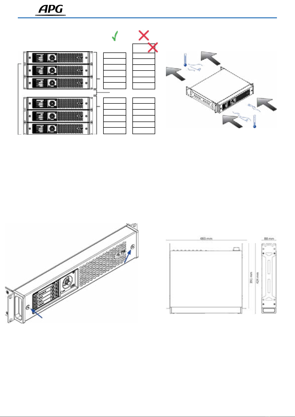
• Install your DA Series Amplifier in well ventilated rack cabinets at a maximum height of 2 meters above the floor.
• Secure both front and rear brackets to the rack.
• Connect the AC Mains connector to a circuit breaker.
• Install the amplifier far from EMF emitting devices.
• Avoid placing the amplifier close to heat generating sources.
Cooling
Do not block the ventilation openings and allow a distance of at least 50 cm from the front and rear ventilation openings of
the amplifier. The DA Series implements a forced-air cooling system to maintain constant operating temperatures. Air enters
from the front panel and exits from the back of the amplifier. The cooling system features variable-speed DC fans controlled
by the heat sink mounted sensors. This ensures that fan noise and internal dust accumulation are kept to a minimum.
In the rare case of overheating, the amplifier is protected by limiting the output power to levels that can be sustained at the
actual ambient temperature. The DA Series amplifiers can be stacked one on top of the other, but it is recommended to leave
one rack unit empty every three amplifiers to guarantee adequate air flow.
Cleaning
Use a dry cloth for cleaning the chassis and the front panel. Air filter cleaning should be scheduled in accordance with the
dust levels in the amplifier’s operating environment. To remove the air filter, detach the front metal cover by unscrewing the
two T20 Torx screws (visual instructions shown below). Use compressed air to remove dust from the filter or wash it with
clean water (let it dry thoroughly before reinstalling).
AC Mains Supply
The DA Series amplifiers implement a universal switching mode power supply, with power factor correction operating in the
range from 100 VAC up to 240 VAC (±10%). AC mains connection can be found in the rear panel through the IEC C20 inlet.
The approved power cord is provided.
Signal Grounding
There is no ground lift switch or terminal on the DA Series amplifier. To minimise hum and/or interference entering the signal
path, always use balanced input connections. For safety, the unit MUST always operate with the electrical safety earth
connected.
Input connections
• 4x Analog inputs (XLR female)
• 2x Stereo AES3 inputs (XLR female)
• 4x Dante/AES67 inputs (EtherCon)
Output connections
• 4x Amplified outputs (NL4 speakON)
• 4x Analog Link Out connectors (XLR male)
• 2x AES3 Link Out connectors (XLR male)
• 4x Dante/AES67 outputs (EtherCon)
Digital Audio Connection
Digital audio is supported via AES3 (AES/EBU) and Dante™ standard protocols. The AES3 connectors accept input channel
pairs through a single balanced XLR cable.
Preliminary operations
Connections

User Guide - DA amplifiers
01/2022DOP_1502_A 11
The DA Series amplifiers offers two Ethercon ports supporting a total of 4-in and 4-out Dante/AES67 channels. Users can
configure the amplifier to operate at one of the following three modes: 2-in x 2-out (at 96kHz), 4-in x 4-out (at 48kHz - default),
4-in x 0-out (at 96kHz). This operation is done under the amplifier Dante settings in ArmoníaPlus.
A computer running the software application Dante Controller™ can be used to configure the Dante properties of DA Series
amplifiers, which are automatically discovered and displayed in Dante Controller™ with the default identifier: AMP-XXXXXX,
where ‘XXXXXX’ is the MAC address of the Dante interface.
Link Out Connectors
There are in total six Link Out connectors directly connected to the amplifier’s analogue and AES3 inputs.
The four Link Out connectors linked to inputs 1 to 4 are simple passive THRU connections.
The other two Link Out connectors are fault-tolerant active repeaters for the AES3 inputs. When the amplifier is on, they
actively repeat the AES3 input signal. If power is lost, an internal relay is switched causing these connectors to work as
simple passive THRU connections.
Switching the amplifier On
To turn on the amplifier, simply connect it to the mains power with the provided power cord. The time between power
on and passing audio is under 10s for analogue sources. Time is longer with Dante sources (about 22 seconds), as the
network is rebooted and patching remade. Once the device is on, it is possible to manually put it in standby mode. Further
information is detailed below in a dedicated section called ‘Power Off’.
Front Panel Controls
The front panel comprises a multitouch capacitive display (1), a rotary encoder with pushbutton (3), a power status LED (4),
and a ‘Back/ArmoníaPlus Callback pushbutton (5).
Users can select what parameters to control and navigate through the different display options and pages available, by
touching the screen, rotating and pushing the rotary encoder, or pushing the ‘Back’ button. Control of some specific
parameters, such as output level and delay, are only possible by rotating the encoder.
From the main menu (2), it is possible to access all the different pages from where control operations can be performed.
Home
The Home page displays the amplifier’s output channels, their level, and the speaker presets assigned to them. From this
page, it is also possible to mute/unmute the outputs by clicking the respective loudspeaker icons .
Level & Delay
The Level and Delay pages allow the control of the amplifier output levels and delay times. Once in one of the two pages,
click on any given output and adjust the level or delay by turning the rotary encoder. When an output is selected, the white
LED behind the encoder will light up, indicating that the parameter can be altered. Note that it is possible to select multiple
outputs at the same time and simultaneously control their relative levels and delay. Selected outputs will display a check
mark next to the speaker preset name.
Clicking the ‘Set Step Size’ button on the top of the display, allows the selection of the change steps to be applied when
rotating the encoder, if finer adjustments are necessary. Level change steps can be set from 1dB (default) to 0.1dB, while
delay steps can be from 10ms to 0.1ms (default is 1ms). For the delay controls, it is also possible to select between metric
(m) or imperial (ft) systems.
Basic operations
1
2
3
4
DA12
HOME
1
2
3
4
-SPEAK...MODEL
-SPEAK...MODEL
-SPEAK...MODEL
-SPEAK...MODEL
>60 dB
>60 dB
>60 dB
BACK
5

User Guide - DA amplifiers
01/2022DOP_1502_A 12
Matrix
The DA amplifier series has an internal 4 x 4 mixing matrix. The Matrix page shows the internal matrix outputs and the matrix
inputs that are routed to them. It is possible to change the routing by clicking on one of the ‘INPUT’ labels and selecting a
new input from the list. These can be any of the four matrix inputs, or a mix of input channels 1 + 2, or channels 3 + 4.
Other routing and mixing configurations can be achieved from ArmoníaPlus. In such cases, the DA will display ‘CUSTOM’ in
the input label.
Source Select
The Source page shows what amplifier input sources are active in each of the 4 internal matrix inputs. These sources can be
any of the 4 amplifier analogue inputs, AES3, or Dante inputs. Manual selection of different sources, as well as configuration
of an automatic backup selection based on signal presence, can be achieved from ArmoníaPlus.
Snapshots
Snapshots are full amplifier configurations that can be saved onboard of the device, and later recalled when necessary.
In the Snapshots page, it is possible to load up to 50 different amplifier configurations that have been previously saved
onboard using ArmoníaPlus. To load a new snapshot to the amplifier, scroll through the list, select one of the snapshots
available, and click the ‘Load’ button at the bottom of the screen.
Out Config
The Out Config page allows quickly bridging the amplifier’s outputs 1 and 2, and/or outputs 3 and 4. Simply click the ‘Bridge’
button to perform the operation, and ‘Unbridge’ to revert to the default configuration.
When n-way loudspeaker presets have been load to n-speaker channels, a new button labelled ‘Split’ will show up in this
page. It is possible to split the ways for individual configuration and control by clicking this button.
Speaker Preset
From the Speaker Preset page, it is possible to load different loudspeaker presets to the amplifier’s outputs. To load a new
preset, click the gear icon , and scroll through the different families, models, and speaker applications. If the preset has been
successfully loaded to the output channel, its name will show in the Speaker Preset page.
Net Config
The Net Config page displays the settings for the amplifier control and Dante network configurations. To scroll between the
amplifier and Dante settings, use the arrows ►. Clicking the gear icon , in one of the two pages, opens the IP configurations,
from where it is possible to set the amplifier or the Dante network to Auto (default) or Static IP, and reset the network
configurations to the default settings.
Node Info
The Node Info page displays general amplifier information, such as its serial number, operating temperature and mains
voltage, firmware versions, and ethercon ports configuration.
From this page it is also possible to access some additional amplifier settings by clicking the gear icon . These settings are
as follows: Lock LCD – allows the user to set a password and subsequently locks the front panel display. When trying to
perform any operation, the user will be requested to insert the password to unlock the screen.
Remove Groups – removes the amplifier from all EQ groups that have been previously created using ArmoníaPlus. Group EQ
settings will be lost under this operation.
Factory Default – sets the amplifier to the factory default settings. Snapshots saved onboard are not deleted.
LCD Brightness – adjusts the brightness of the front panel display. Auto Fade – allows different screen on/off options, where
‘Always On’ never turns the screen off, ‘Auto Fade’ causes the screen to operate at lower brightness after 30s of not being
used, and ‘Auto Off’ causes the screen to automatically turn off after 30s of not being used. A simple touch to the screen
brings it back to its normal operation status.
Power OFF
From the Power Off page, it is possible to manually put the amplifier in standby mode by clicking the ‘Power OFF’ button.
Pushing and holding the rotary encoder for 4s also triggers the standby mode.
The power status LED (4) is green when the amplifier is ON and becomes red when the amplifier is in standby mode.
Once the amplifier is in standby, to turn it back on, simply touch the
screen or push the rotary encoder, and select ‘Power ON’.
FW Update
Amplifier and Dante firmware updates can be performed via ArmoníaPlus. During the firmware update, the display will show
the message ‘Updating Firmware’, and a status bar will show the progress through the various phases.

User Guide - DA amplifiers
01/2022DOP_1502_A 13
The DA Series amplifier supports Dante networking. The two- gigabit ports are internally connected via a Gigabit switch to
simplify wiring and eliminate the need for external network switches in small systems. Control and Dante audio are available
in both ports by default. This configuration can be checked from the front panel screen under Node Info > ETH 1/ETH2.
Note: the DA does not support Dante redundancy, therefore, do never connect the two ethercon ports to separate primary
and secondary Dante networks simultaneously.
IP Addressing
The factory default network configuration is AUTO IP/DHCP.
STATIC IP policy can also be adopted and configured through ArmoníaPlus or the screen panel (see ‘Net Config’ section).
If a DHCP server is not active in the network, the amplifier platform initiates an auto-configuration with a local numeric
network address (of the type 169.254.X.Y and subnet mask 255.255.0.0).
It is recommended to always turn on the DHCP server before connecting the amplifiers.
ArmoníaPlus System Manager is the default interface that allows setting and customisation of the DA Series amplifiers. Note
that whenever the DA is connected to ArmoníaPlus, the front panel display operations are disabled.
ArmoníaPlus can be installed on a PC running Windows (XP SP3 and higher).
For a successful connection, both ArmoníaPlus and the DA Series must belong to the same subnet.
Download ArmoníaPlus System Manager for free from the website: https://www.powersoft.com/en/software/armoniaplus/
Networking
ArmoníaPlus System Design
User Guide - DA amplifiers
01/2022DOP_1502_A 14
Location Cooling
Exposing the filters Dimensions
2 m max from floor
1 RU
6
5
4
3
2
1
7
6
5
4
3
2
1
1 RU
6
5
4
3
2
1
1 RU
6
5
4
3
2
1
T20 Torx screw.

User Guide - DA amplifiers
01/2022DOP_1502_A 15
Pinouts
HOT
HOT
COLD COLD
GND GND
Analog/AES3 input XLR-M pinout
Pin# Terminal
1 Ground (GND)
2 Positive (+)
3 Negative (-)
Analog/AES3 input XLR-F pinout
Pin# Terminal
1 Ground (GND)
2 Positive (+)
3 Negative (-)
Output NL4 Speakon-F pinout
Single Ended
1+ Speaker A positive terminal
1- Speaker A negative terminal
2+ Speaker B positive terminal
2- Speaker B negative terminal
Bridged
1+ Speaker positive terminal
2- Speaker negative terminal
Even Channels (CH2 - CH4)
1+ Speaker positive terminal
1- Speaker negative terminal
2+ Not connected
2- Not connected
Network Connector RJ45 pinout
Color code (TIA/EIA-568-B) Pin
ORANGE / WHITE
ORANGE
GREEN / WHITE
BLUE
BLUE / WHITE
GREEN
BROWN / WHITE
BROWN
1
2
3
4
5
6
7
8
A
B
1+
1+
1+
1-
1-
2+
2+
2-
2-
2-

User Guide - DA amplifiers
01/2022DOP_1502_A 16
Front panel
Rear panel
1
3
2
4
Control Panel
Main menu
Rotary encoder pushbutton
Power status LED
«Back/ArmoníaPlus Callback» pushbutton
USB Port
Reserved for servicing purposes
1
2
3
4
10
9
14 13 22 21 20 19
8
7
12 11 18 17 16 15 24 23
Output section
CH1 (1+/-) CH2 (2+/-)
CH2 (1+/-) N.C. (2+/-)
CH3 (1+/-) CH4 (2+/-)
CH4 (1+/-) N.C. (2+/-)
AES3
AES3 In 1-2 (1GND/2+/3-)
AES3 In 3-4 (1GND/2+/3-)
AES3 Link Out 1-2 (1GND/2+/3-)
AES3 Link Out 3-4 (1GND/2+/3-) Network Connectors
ETH 1 (RJ45)
ETH 2 (RJ45)
AC Mains Connector
IEC C19
Input 1 (XLR-F)
Input 2 (XLR-F)
Input 3 (XLR-F)
Input 4 (XLR-F)
Link Out 1 (XLR-M)
Link Out 2 (XLR-M)
Link Out 3 (XLR-M)
Link Out 4 (XLR-M)
Input section
7
8
9
10
11
12
13
14
23
24
22
21
20
19
18
17
16
15

Arbane Groupe
8 Rue Johannes Gutenberg - 44340 Bouguenais- France
Tél : 02.40.46.66.64
www.apg.audio
Table of contents


