Arc Machines M96 User manual

M96 WELD HEAD
OPERATION MANUAL

Doc No. 7400481
MODEL 96
TUBE TO TUBESHEET WELD HEAD
OPERATION MANUAL
NOTICE
This document and the information contained herein is the property of Arc Machines,
Inc.. It is proprietary and submitted and received in confidence. It shall be used only for
the purpose for which it is submitted and shall not be copied in whole or in part without
the prior expressed written permission of Arc Machines, Inc.
The information in this document has been carefully reviewed and is believed to be
accurate.
Information and instructions in this document are subject to change and Arc Machines,
Inc. reserves the right to change specifications and data without notice.
WARNING
The nature of the GTAW process creates some POTENTIAL HAZARDS. In accordance
with international safety regulations the EXCLAMATION SYMBOL indicates that this
equipment is considered HAZARDOUS until an operator has been made aware of these
POTENTIAL HAZARDS by reading the appropriate Arc Machines, Inc. Power Supply
and/or Weld Head Operation Manual. The LIGHTNING FLASH SYMBOL indicates that
there are potential electrical hazards. The use and display of these symbols make it the
OPERATOR’S RESPONSIBILITY TO INSURE THAT HE HAS READ AND/OR BEEN
MADE AWARE OF ALL OF THE SAFETY-RELATED ITEMS CONTAINED IN THESE
MANUALS.
Publication date : November, 2011
Copyright 2010 by Arc Machines, Inc.
All rights reserved
REV
DCO #
CHANGE DESCRIPTION
DATE
APR
A
E5424 CLARIFIED ATTACHMENT 1/28/10 DC
B E6181 UPDATED IMAGES AND TEXT 4/18/11 BL

Doc No. 7400482
MODEL 96
TUBE TO TUBESHEET WELD HEAD
OPERATION MANUAL
Table of Contents
Chapter Page No.
1.0 Introduction……………………….. …… 3
2.0 Unpacking………………………………. 4
3.0 Cable hook up…………………………. 5
4.0 Rotation (speed) Calibration…………. 7
5.0 Mandrel installation……………………… 9
6.0 Electrode geometry & installation……… 11
7.0 Gas chambers…………………………. 15
8.0 Nose ring……………………………….. 16
9.0 Shielding gas…………………………… 17
10.0 Cleaning and maintenance…………… 18
11.0 Storage…………………………………. 19
12.0 Tube & Tubesheet Preparation
considerations………………………… 19
13.0 Available Options…………………….. 20

Doc No. 7400483
MODEL 96
TUBE TO TUBESHEET WELD HEAD
OPERATION MANUAL
1.0 INTRODUCTION
The Model 96 Weld Head is designed for Tube to Tubesheet fusion welding,
using the GTAW process. Tubes can be flush, slightly projected above, or
recessed below the tubesheet. It is designed to accommodate tube sizes from
0.37 (9.4mm) I.D. to 2.12” (53.8mm) O.D., and works in conjunction with all Arc
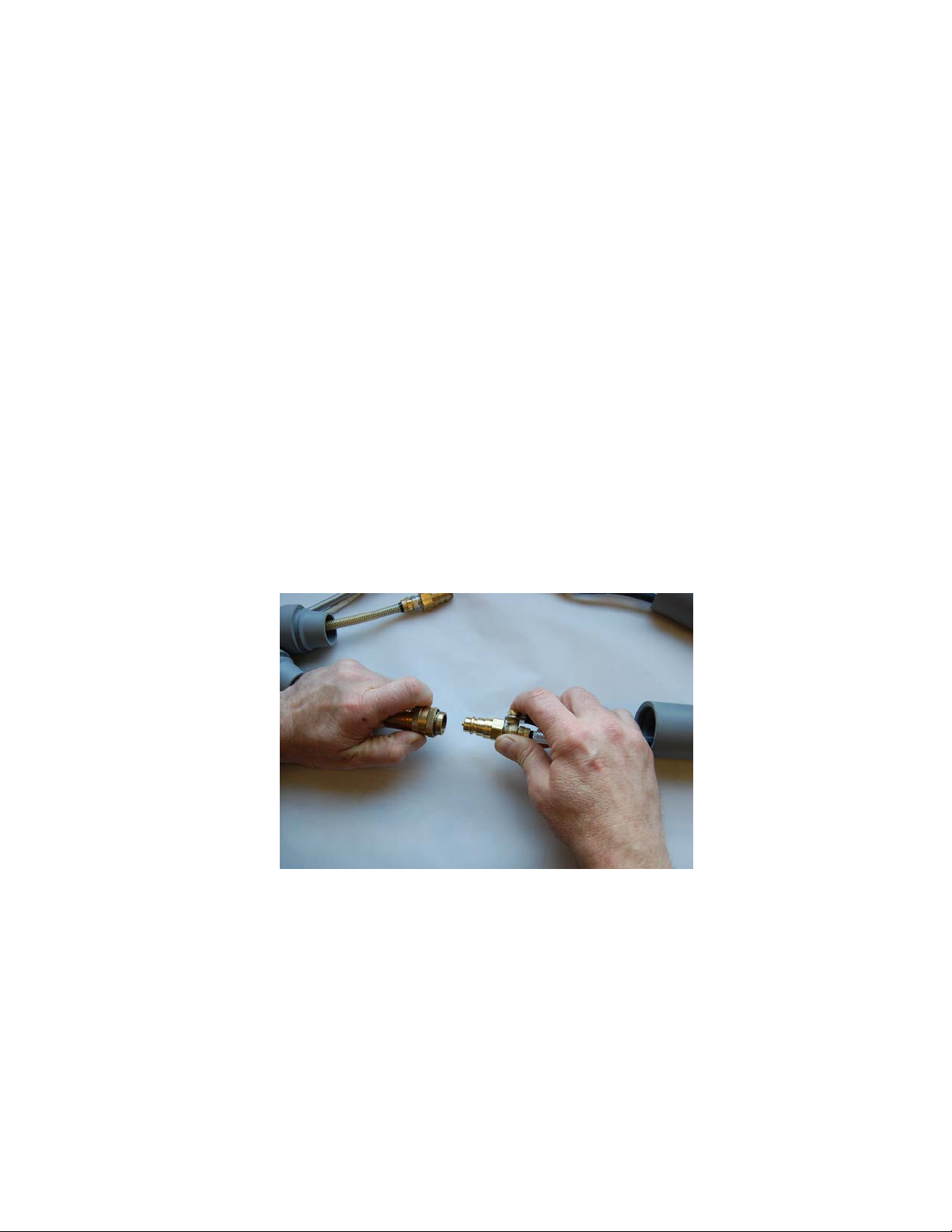
Machines power supplies. The (optional) cooling unit (available with all AMI
fusion Power Supplies) is required for use with the Model 96 weld head.
A pneumatically operated expanding mandrel (integral to the weld head) is used
to hold it firmly in position, and concentric to the weld joint. Each mandrel will
accommodate a specific tube I.D. size range. A fixed electrode maintains a
constant electrode to work (arc gap) distance as it rotates around the joint.
A gas chamber surrounds the arc and weld joint providing excellent shielding gas
coverage. This chamber can be clear or opaque. For initial set up and weld
schedule development, a clear (transparent) chamber may be used, allowing
viewing of the arc.
(BE SURE TO USE APPROPRIATE EYE PROTECTION).
For production purposes it is recommended that the opaque chamber be used.
Attached to the end of the gas chamber is a nose ring which is
designed to sit directly onto the tubesheet, providing a repeatable
and consistent arc gap. A standard (generic) nose ring is supplied with
the Model 96. This ring has a large hole in the end to accommodate a
wide variety of tube sizes and tube spacing. For more gas sensitive
applications (such as when welding Titanium), where shielding gas
coverage is more critical, special application-specific nose rings are
available.

Doc No. 7400484
MODEL 96
TUBE TO TUBESHEET WELD HEAD
OPERATION MANUAL
1.0 INTRODUCTION (cont’d.)
Electrode holders to fit 1/16” (1.6mm) and 3/32” (2.4mm) diameter
electrodes come standard with the Model 96. A 0.040” (1.0mm)
electrode holder as well as an extended (3/32”) holder for tube over
2.00” (50.8mm) O.D. are optional. The design is such that when the
correct length electrode is properly installed into the electrode holder,
the arc gap (distance from electrode tip to tube) is automatically set.
The electrode holder is mounted on a pivot arm which swings in or out
to accommodate various tube diameters.
The integral 10ft. (3 meter) cable contains electrode power, shielding
gas, motor (electrode rotation) control, coolant (in/out) and a ground
cable.
CAUTION
A thorough understanding of the Arc Machines
Power Supply being used is required before
installation or operation is attempted.
2.0 UNPACKING
When unpacking the weld head use extreme caution in removing the
plastic bag covering the cable connectors. Tools such a knife of other
sharp object can cut the cables.

Doc No. 7400485
MODEL 96
TUBE TO TUBESHEET WELD HEAD
OPERATION MANUAL
3.0 CABLE HOOK UP
CAUTION
Always turn the power supply off before making any cable connections.
The Model 96 weld head comes supplied with an integral 10ft (3 m) cable.
This cable is NOT connected directly to the power supply. It must be mated to
the power supply via an adapter pig-tail or adapter cable. Extension cables may
also be used. The use of an extension cable does not eliminate the requirement
for an adapter. If an extension cable is used, it is connected between the power
supply and the adapter. After making connections, to prevent power and ground
connectors for coming in contact with each other, slide the rubber boots
together. See fig. 6
3.1 Connect the power and ground fittings by pulling the brass ring back
and inserting the male fitting into the female fitting, until it is fully
seated. If it is not fully seated, it will leak water or potentially come
apart. See fig. 1.
Fig. 1

Doc No. 7400486
MODEL 96
TUBE TO TUBESHEET WELD HEAD
OPERATION MANUAL
3.0 CABLE HOOK UP (contd.)
3.2 To connect the male to female (chrome) gas fittings, unscrew the
(4-40) socket head screw to allow the latch to open far enough to fully
seat the two fittings. Once the fittings are latched together, lightly
tighten this screw to prevent accidental disconnection. See fig. 2.
Fig. 2
3.3 Connect the motor control connector by aligning the key to the slot,
and lightly tightening the outer ring. Be careful not to cross-thread this
ring. See fig. 3.
Fig. 3

Doc No. 7400487
MODEL 96
TUBE TO TUBESHEET WELD HEAD
OPERATION MANUAL
2.0 CABLE HOOK UP (contd.)
Fig. 4
3.4 Slide the boots together securely to protect the connectors and fittings
from dirt, and to prevent the power and ground connectors from
coming in contact with each other. Fig. 4.
3.4 Before connecting the air line, first be sure that the air actuation
switch on the handle is in the up (off, un-actuated) position. See
fig. 6. Connect the air line to a clean, dry air source of 90-120
PSI (6.2 – 8.3 Bar).
4.0 ROTATION (SPEED) AUTO-CALIBRATION
Before welding, the electrode rotation motor must be calibrated to the
power supply. Most power supplies include an auto calibration function in
the software. Refer to the power supply operation manual for specifics on
auto calibration. The Model 96 has a maximum travel speed of 10.0 RPM
Should the power supply indicate that the weld head requires
calibration adjustment, the calibration potentiometer can be
accessed through a hole to the right of where the cable is attached.
See fig. 5

Doc No. 7400488
MODEL 96
TUBE TO TUBESHEET WELD HEAD
OPERATION MANUAL
4.0 ROTATION (SPEED) AUTO-CALIBRATION (contd.)
Fig. 5
4.1 ROTATION (SPEED) MANUAL CALIBRATION
Follow the instructions on your power supply in making
adjustments to the potentiometer. Repeat this procedure until the
power supply indicates that the head is calibrated.
For power supplies that do not have auto calibration software.
Some power supplies do not have auto calibration software. In this
case, the weld head motor is manually calibrated by creating a weld
program that should rotate the electrode 360 degrees. ie:1 RPM for a
total of 60 seconds, 2 RPM for a total of 30 seconds, 3 RPM for
a total of 20 seconds, etc. Select a speed (RPM) and corresponding
time close to or equal to the speed that you intend on welding at to
achieve the most accurate calibration.
4.2 The power supply must be in the “TEST” mode. Create a one level
weld schedule at your selected RPM. Amperage and pulse rate
settings may be set to any value, as during rotation calibration no
arc will be established. Set rotation mode to “CONT” (continuous
rotation). Set rotation delay and down slope times to 0.0.

Doc No. 7400489
MODEL 96
TUBE TO TUBESHEET WELD HEAD
OPERATION MANUAL
4.1 ROTATION (SPEED) MANUAL CALIBRATION (contd.)
4.3 Add one additional level with a duration of 5 or more seconds, with
the rotation mode set to “OFF”. This additional level (with rotation off)
will hold the electrode at its stopped position allowing the operator to
see if it traveled too far or not far enough.
4.4 Be sure the power supply is in the “TEST” mode. Make note of the
electrode start location, and run the program. Should the electrode
rotate too fast, stopping past the start location (traveling more than
360 degrees), slow it down by turning the potentiometer counter
clockwise (CCW). Should the rotation be too slow, stopping before it
reaches its start location, (rotating less than 360 degrees) turn the
potentiometer clockwise (CW). Continue this procedure until the
electrode stops after 360 degrees of travel.
5.0 MANDREL INSTALLATION
The Model 96 uses an I.D. expanding mandrel to position and hold
the weld head firmly in place, and concentric to the tube being welded.
Mandrels are available for any size tube I.D. from 0.375” (9.5mm) through
2.0” (50.8mm).
5.1 To install the mandrel, first be sure that the air source is
disconnected, and that the air actuation switch is in the
“release” (UP) position. This is to prevent accidental mandrel
actuation, (expansion) and possible over-stretching of the collet.
See fig. 6.

Doc No. 74004810
MODEL 96
TUBE TO TUBESHEET WELD HEAD
OPERATION MANUAL
5.0 MANDREL INSTALLATION (contd.)
CAUTION!
Expanding the mandrel when it is not inserted into
an appropriately sized tube can damage it.
Fig. 6
Mandrel release position.
5.2 Remove the thumb nut and washer from the top of the
mandrel and slide the mandrel shaft into the center hole next
to the electrode holder. Slowly rotate the mandrel until the
threaded end protrudes through the top of the weld head.
Reinstall the washer and thumb nut, and gently hand-tighten.
CAUTION!
TO PREVENT OVER-STRETCHING OF THE MANDREL,
DO NOT ACTUATE THE AIR CYLINDER UNLESS THE MANDREL IS
INSTALLED INTO THE APPROPRIATE SIZE TUBE.
THE MANDREL IS SPRING-LOADED. DO NOT ATTEMPT TO
DIS-ASSEMBLE IT WHILE IT IS INSTALLED IN THE WELD HEAD

Doc No. 74004811
MODEL 96
TUBE TO TUBESHEET WELD HEAD
OPERATION MANUAL
6.0 ELECTRODE GEOMETRY AND INSTALLATION
CAUTION
To prevent the possibility of electrical shock, the power
supply must be turned off or set to the “TEST” mode before
proceeding with electrode installation or removal.
6.1 The recommended electrode type is 2% Ceriated. (AWS Spec.
A5.12/A5.12M, Orange tip). This type of electrode provides superior
arc starting and longer life than 2% Thoriated electrodes. Other types
can also be used. Consult factory for recommendations.
6.2 The Model 96 comes with electrode holders for both 1/16” (1.6mm)
and 3/32” (2.4mm) diameter electrodes. A 0.040” (1.0mm) diameter
electrode holder is available.
6.3 The design of the Model 96 is such that a 1.000” (25.4mm) long
electrode, (properly installed in the electrode holder) will stick out the
same distance as the feet or tabs on the nose ring, which sits on the
surface of the tubesheet. Use this 1.000” (25.4mm) dimension to
calculate the appropriate electrode length for a flush tube application.
ELECTRODE LENGTH FORMULA:
1.000” (25.4m) minus the arc gap = electrode length.
6. 4 Electrode geometry and Arc Gap are primarily based on the tube
material and wall thickness. Although the Model 96 can
accommodate a wide variety of materials and preps (recessed, flush
or projected), the most common applications are stainless steel tube,
inserted flush with the tubesheet. The following two charts are based
on these types of applications.
Use this chart to establish a recommended electrode diameter.
Tube/Pipe
Wall thickness
Electrode
Diameter
0.015”–0.035” (.38 –.76mm) 0.040” or 1/16” (1.0 or 1.6mm)
0.036” – 0.083” (.91 – 2.1mm)
1/16” (1.6mm)
0.084” – 0.250” (2.1 – 6.3mm)
3/32” (2.3mm)
Fig. 7

Doc No. 74004812
MODEL 96
TUBE TO TUBESHEET WELD HEAD
OPERATION MANUAL
6.0 ELECTRODE GEOMETRY AND INSTALLATION (Cont’d.)
6. 5 Use this chart to determine a recommended Arc Gap and electrode
Tip Diameter.
Tube/Pipe Wall
Thickness
Recommended
Arc Gap
Recommended Tip
Diameter
0.015”–0.035”(.38 –.89mm) 0.020”-0.030”(0.50-76mm)
0.010”-0.020” (.25-.50mm)
0.036”-0.083” (.91-2.1mm) 0.030”-0.050” (.76-1.3mm)
0.020” -0.030” (.50-.76mm)
0.084”-0.250” (2.1-6.3mm) 0.050”-0.070” (1.3-1.8mm)
0.030”–0.040” (.76- 1.0mm)
Fig. 8
6.6 Loosen the socket head electrode lock screw in the electrode holder.
6.7 Install an electrode, and be sure it is fully seated and bottomed-out in
the holder. Tighten the lock screw. See fig. 9
CAUTION
DO NOT INSTALL AN ELECTRODE INTO AN OVER-SIZED
ELECTRODE HOLDER.
ALWAYS USE THE CORRECT SIZE ELECTRODE HOLDER.
Fig. 9

Doc No. 74004813
MODEL 96
TUBE TO TUBESHEET WELD HEAD
OPERATION MANUAL
6.0 ELECTRODE GEOMETRY AND INSTALLATION (Cont’d.)
6.8 Projected or recessed tubes.
If your tubes ends are projected above or recessed below the surface
of the tubesheet, they can still be welded, however since there are so
many possible combinations of materials, projection or recess
dimensions, tube sizes and wall thicknesses, consult the factory for
recommendations.
6.9 Electrode radial positioning.
The electrode must be positioned with respect to the tube O.D. Most
applications work best with the centerline of the electrode either in line
with the tube O.D., or slightly outside the tube O.D.
CAUTION
POSITIONING THE ELECTRODE TOO CLOSE TO THE TUBE I.D. CAN
CAUSE THE WELD PUDDLE TO “ROLL” INTO THE TUBE I.D.,
PREVENTING THE REMOVAL OF THE MANDREL.
BEFORE WELDING YOUR TUBESHEET, VARIFY THE WELD HEAD
SET UP AND WELD SCHEDLE ON A SACRIFICIAL TUBESHEET
MOCK UP.
6.10 With a mandrel installed (see 5.0 for mandrel installation) slide a
piece of tube (the same size as the tubes in the tubesheet) onto the
mandrel, far enough to reach within 3/8” (10mm) of the electrode
tip. Expand the mandrel by pressing the air valve down. Loosen the
pivot screw in the electrode holder, and position the electrode with
respect to the tube O.D., then tighten the pivot screw. See fig. 10.

Doc No. 74004814
MODEL 96
TUBE TO TUBESHEET WELD HEAD
OPERATION MANUAL
6.0 ELECTRODE GEOMETRY AND INSTALLATION (Cont’d.)
Fig. 10
6.11 Once the electrode is positioned properly you can measure
the distance across the electrode and the mandrel using a
veneer caliper (or other accurate measuring devise), and
record this dimension for future welding of this application.
See fig. 11.

Doc No. 74004815
MODEL 96
TUBE TO TUBESHEET WELD HEAD
OPERATION MANUAL
6.0 ELECTRODE GEOMETRY AND INSTALLATION (Cont’d.)
Fig. 11
7.0 GAS CHAMBERS
The Model 96 features a cylindrical gas chamber to surround the
weld, providing excellent gas coverage. The weld head comes with
an opaque chamber. A clear glass chamber that can aid in weld
schedule development (as it allows the operator to see the weld puddle
being formed), is available as an optional accessory.
7.1 To remove the chamber, first release the two side latches, and
remove the nose ring. Grip the chamber and twist it while pulling it
away from the weld head.
7.2 Install the gas chamber by pressing it onto the O-ring in the
housing. Be sure it is fully seated. Applying a very thin film
of light oil or O-ring lube to the top of the chamber (on the I.D.) or to
the O-ring will make installation and removal easier.

Doc No. 74004816
MODEL 96
TUBE TO TUBESHEET WELD HEAD
OPERATION MANUAL
7.0 GAS CHAMBERS (Cont’d.)
7.3 Attach the nose ring to the end of the gas chamber, and lock it
in place with the two side latches. See fig. 12.
Fig. 12
8.0 NOSE RINGS
The Model 96 uses feet or tabs on the bottom of the nose ring to rest on
the tubesheet. The nose ring that comes standard with the head is
considered a generic nose ring, and can be used for multiple applications.
Shown in Fig. 12.
For applications that require higher levels of purge quality, either due to
the material, (such as when welding Titanium) or in the case of close tube
spacing (where some of the gas flows into adjacent tubes, diminishing the
purge quality), application specific nose rings are available. These nose
rings feature a smaller center hole as well as three screw-on feet.

Doc No. 74004817
MODEL 96
TUBE TO TUBESHEET WELD HEAD
OPERATION MANUAL
8.0 NOSE RINGS (Cont’d.)
The feet are positioned in a pattern so when the head is rotated into the
correct position on the tubsheet, all three feet will be positioned in the
space between tubes, allowing the head to sit flat and parallel to the
tubesheet.
CAUTION
Do not initiate a weld sequence unless all nose
ring feet are sitting flat on the tubesheet,
and not on adjacent welds.
9.0 SHIELDING GAS (Arc Gas)
The type of shielding gas used has a profound effect on the character of
the arc and the depth of weld penetration. The most commonly used
shielding gas used is Argon. Gas mixtures of 95% Argon/5% hydrogen
or 75% helium/25% argon are sometimes used to achieve deeper
penetration. Consult the factory for recommendations.
The Model 96 is designed to flow arc gas at 20 - 40 CFH (9.4 – 18.9 lPM).
As a general rule, use lower flow rates for small diameter tube and higher
flow rates for larger diameter tubes. This is because the larger the tube is,
the more gas can escape down the tube.
Use the Manual Purge button on your power supply to open the solenoid,
and set the flow rate at your flow meter.
Note: If the system is being hooked up for the first time, or if it has been a
number of hours since it was last used, it’s a good idea to initiate
the Manual Purge button on the power supply to clear the lines of
oxygen for a few minutes before initiating a weld sequence.

Doc No. 74004818
MODEL 96
TUBE TO TUBESHEET WELD HEAD
OPERATION MANUAL
10.0 CLEANING AND MAINTENANCE
If the weld head is to be stored for more than 1 month, the residual water or
water/coolant mix should be purged from the hoses and weld head to
minimize internal corrosion. This is also important if the weld head is to be
stored where the temperature might fall below freezing, as trapped water
can freeze and damage weld head and/or hose internals.
Although you may not be storing the adapter and /or extension cables,
leave them hooked up to the weld head when purging out the water.
10.1 To drain the coolant from the weld head and cables, use Arc
Machines, Inc. fitting part number 294-PB-06. Unplug the water
“supply” line from the cooling unit, (leaving the water “return” line
connected to the cooling unit) and attach the (female) fitting
(294-PB-06) to the disconnected “supply” line. See Fig. 13.
Fig. 13
10.2 Using a pressurized air source of maximum 20 PSI, (139 Kp)
(1.38 Bar) blow air into the fitting to force the water out of the
cables and weld head, and back into the cooling unit. See fig. 13.

Doc No. 74004819
MODEL 96
TUBE TO TUBESHEET WELD HEAD
OPERATION MANUAL
10.0 CLEANING AND MAINTENANCE
CAUTION, DO NOT USE AIR PRESSURE
ABOVE 20 PSI (139 Kp) (1.38 Bar)
10.3 To clean the weld head, use a lint-free cloth and alcohol to wipe
down all surfaces.
11.0 STORAGE
11.1 Attach the dust cap to the electrical connector, and store the weld
head in a clean, dust-free area.
11.2 Do not store the weld head for more than 1 month without first
draining the coolant from the weld head and hoses. Refer to chapter
10.0 for coolant draining instructions.
12.0 TUBE & TUBESHEET PREPARATION CONSIDERATIONS
As with all welding applications, regardless of the welding process or the
material being welded, cleanliness of the materials being welded is of
upmost importance. Dirt, oil, paint, hydraulic fluid, oxidation, or any other
contaminant must be removed from both the tube and the tubesheet prior
to installing the tube into the tubesheet. Cleaning the joint after the tube
has been installed will not be adequate, as contaminants trapped between
the tube and tubesheet cannot be removed, and will cause weld defects
and/or porosity. Additionally, contaminants can adhere to the electrode
and contaminate it.
Fit up between the tube O.D. and the tubesheet hole I.D. is also very
important. If the tube is not in good contact with the tubesheet, weld
repeatability will suffer. Weld puddle characteristics will not be consistent
if the fit up is not consistent. In order to get repeatable thermal transfer
between the tube and the tubesheet, they must be in good contact with
each other.
Table of contents
Other Arc Machines Welding System manuals