Arc Machines 207A User manual


MODEL 207A AND 207A-1
OPERATION MANUAL
Doc. No. 740044
Rev F
NOTICE
This document and the information contained herein is the property of Arc Machines, Inc..
It is proprietary and submitted and received in confidence. It shall be used only for the
purpose for which it is submitted and shall not be copied in whole or in part without the
prior express written permission of Arc Machines, Inc.
The information in this document has been carefully reviewed and is believed to be
accurate. However, no responsibility is assumed for inaccuracies.
Information and instructions in this document are subject to change and Arc Machines, Inc.
reserves the right to change specifications and data without notice.
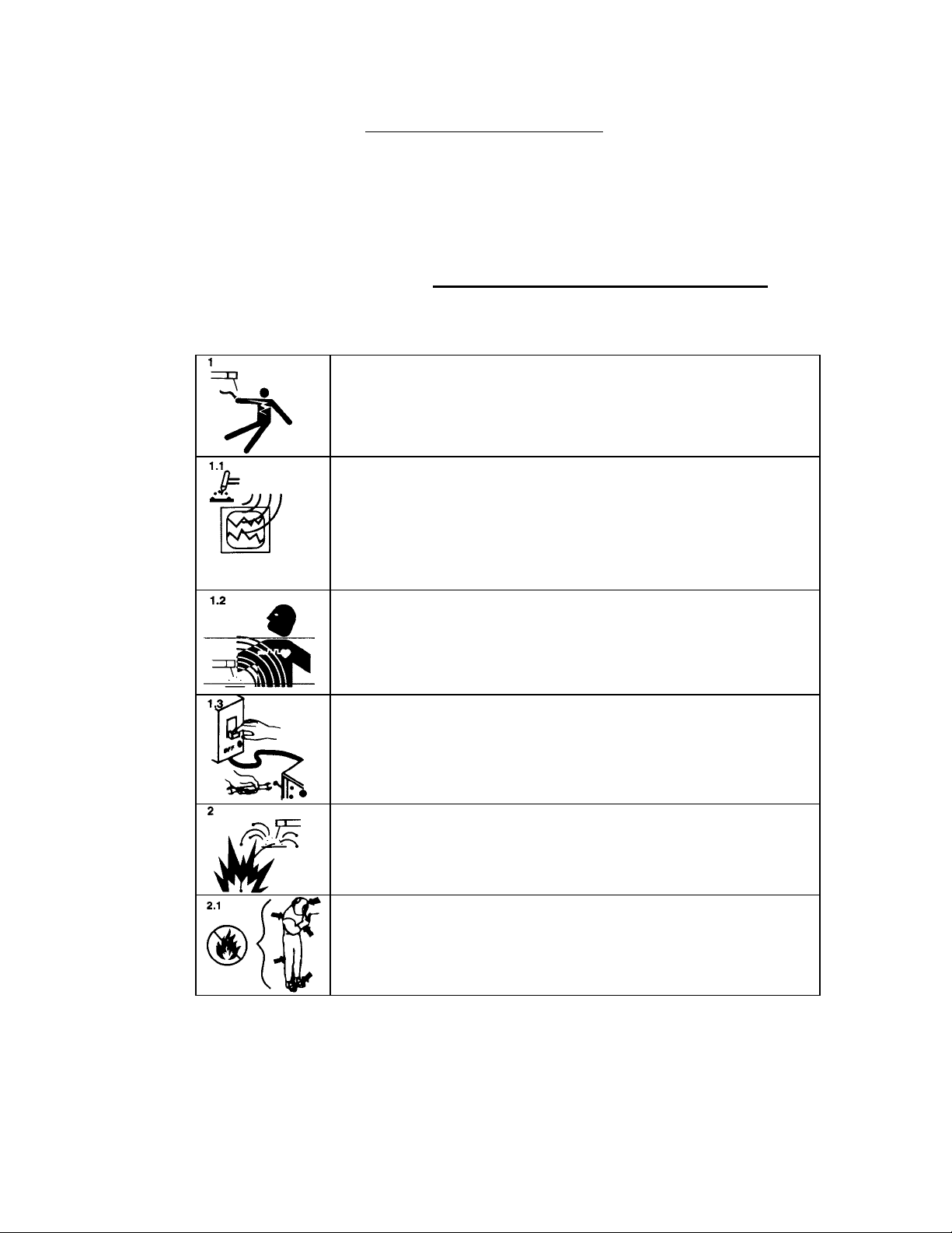
WARNING
The nature of the GTAW process creates some POTENTIAL HAZARDS. In accordance
with international safety regulations the EXCLAMATION SYMBOL indicates that this
equipment is considered HAZARDOUS until an operator has been made aware of these
POTENTIAL HAZARDS by READING THIS MANUAL. The LIGHTNING FLASH
SYMBOL indicates that there are potential electrical hazards. The use and display of these
symbols make it the OPERATOR’S RESPONSIBILITY TO INSURE THAT HE HAS
READ AND/OR BEEN MADE AWARE OF ALL OF THE SAFETY-RELATED ITEMS
CONTAINED IN THIS MANUAL.
Publication date : First Edition - August 15, 1989
Copyright 1989 by Arc Machines, Inc.
All rights reserved
REV. DCO # CHANGE DESCRIPTION
DATE
APR
A
N/A
Revised Pg I, ii, iii,iv 9/29/93 GPE
B 2357 Revised to include required IEC-974 information 8/15/96 GPE
C 3059 Added M227/207-CW info: pg. iv, v, 1.1, 3.7, 4.12, 7.5, 7.7,
8.1, 8.2, 8.3.
04/20/98 GPE
D 3583 Revised page 7.4 Step 13 add new Current Offset
adj.
3/20/00 GPE
E 3684 Removed ref to Miller coolant page 8.2 7/20/00 GPE
F 5779 Removed 207A-HP (OBS) 8/10/10 DC
i

MODEL 207A AND 207A-1
OPERATION MANUAL
Doc. No. 740044
Rev F
EFFECTIVITY
Features and operation of the Model 207A, Model 207A-1 are derived mostly from
SOFTWARE. This document is based on the latest STANDARD version of
SOFTWARE at the time of last revision (see revision page).
Some deviations in actual operation, from this document, are possible depending on
the software version of a particular machine. Please feel free to contact Arc Machines
Service Department for documentation or information on how software updates effect
this document.
ii

MODEL 207A AND 207A-1
OPERATION MANUAL
Doc. No. 740044
Rev F
TABLE OF CONTENTS
SECTION DESCRIPTION PAGE
SECTION I INTRODUCTION
1.0 Introduction 1.1
1.1 Safety Precautions 1.2
1.2 Operational Precautions 1.5
1.3 Shock Hazard Warning 1.7
SECTION II SPECIFICATIONS
2.0 Electrical 2.1
2.1 Physical Construction 2.3
2.2 Programmable Functions and Ranges 2.3
2.3 Multi-Level Functions 2.3
2.4 Ambient Temperature Range 2.4
2.5 Cable Operating Length Limits 2.4
SECTION III INSTALLATION
3.0 Inspection 3.1
3.1 Power Connections 3.1
3.2 Welding Gas Connections 3.2
3.3 Adapter Cable to M-207A Installation 3.7
3.4 Weld Head Installation 3.7
SECTION IV SYSTEM FUNCTIONS
4.0 Introduction 4.1
4.1 Functional Description, General 4.1
4.2 Weld Library and Weld Description 4.3
4.3 Weld Sequence 4.3
4.4 Panel Keys 4.9
4.5 Operate Mode Switch 4.11
4.6 Faults 4.12
4.7 Sensor 1,2,3 Faults 4.13
4.8 Set-Up Functions 4.13
4.9 Glossary of Abbreviations 4.15
4.10 Glossary of Terms 4.16
iii

MODEL 207A AND 207A-1
OPERATION MANUAL
Doc. No. 740044
Rev F
TABLE OF CONTENTS
SECTION DESCRIPTION PAGE
SECTION V OPERATION
5.0 Introduction 5.1
5.1 Initial Power On 5.1
5.2 Use of Next/Prev 5.2
5.3 Weld Schedule Selection 5.4
5.4 Viewing Function Values 5.5
5.5 Overriding Function Values Before Seq 5.6
5.6 Overriding Function Values During Seq 5.7
5.7 Set Up Functions 5.7
5.8 Auto Rotation Calibration 5.11
5.9 Manual Rotation Calibration 5.13
5.10 Welding Operation 5.15
5.11 Printer Operation 5.16
SECTION VI PROGRAMMING
6.0 Introduction 6.1
6.1 Create A Weld Schedule 6.1
6.2 Modify A Weld Schedule 6.4
6.3 Copy a Weld Schedule 6.5
6.4 Transfer/Receive A Weld Schedule 6.6
6.5 Delete A Weld Schedule 6.7
SECTION VII CALIBRATION
7.0 Introduction 7.1
7.1 Equipment Required 7.1
7.2 Current Servo 7.2
7.3 General Maintenance 7.5
7.4 System Fault Corrections 7.6
7.5 Error Messages 7.9
7.6 Miscellaneous Maintenance Items 7.10
SECTION VIII OPTIONS
8.0 Introduction 8.1
8.1 M227/207-CW & M207-CW Cooling Unit 8.1
8.2 M-207-RP Remote Pendant 8.3
8.3 M-207-EMM External Memory Module 8.7
iv

MODEL 207A AND 207A-1
OPERATION MANUAL
Doc. No. 740044
Rev F
TABLE OF CONTENTS
LIST OF ILLUSTRATIONS
FIGURE DESCRIPTION PAGE
FIGURE 1 SYSTEM CONFIGURATION 1.4
FIGURE 2 INSTALLATION LOCATIONS 3.3
FIGURE 3 AC POWER SET-UP 3.4
FIGURE 4 CABLE CONNECTIONS 3.5
FIGURE 5 SEQUENCE TIMING CHART 4.7
FIGURE 6 PANEL KEY LOCATIONS 4.8
FIGURE 7 USE OF NEXT/PREV KEYS 5.3
FIGURE 8 M227/207-CW & M207-CW INSTALLATION 8.6
v

MODEL 207A AND 207A-1
OPERATION MANUAL
Doc. No. 740044
Rev F
SECTION I - INTRODUCTION
1.0 INTRODUCTION
This manual is intended to assist users of this equipment in set up and basic
operation. Automatic fusion welding requires a good deal of operator expertise
which requires AMI supplied training. THIS MANUAL IS NOT INTENDED AS
A SUBSTITUTE FOR THAT TRAINING.
The basic Model 207A (M-207A) welding power supply is part of a complete
welding system intended for fusion welding of metal tubes, pipes and fittings (see
Figure 1). The complete system consists of the M-207A power supply, adapter
cable, gas lines and any of the AMI Model 9 (M-9) series of tube welding heads
(M-9 heads sold separately).
The M-207A power supply provides GTAW current with pulsation controls, high
frequency arc starting, purge gas controls, weld head arc rotation and automatic
timing functions. The M-207A is supplied (as standard) ready to weld. Users
need only to supply input AC power, regulated gas source with flow meter and the
appropriate weld head or manual torch.
Some operating conditions may require optional components such as the remote
pendant option (M-207-RP), weld head cooling unit option (M227/207-CW or
M207-CW) and extension cables. The M-207A family of options also includes
quality assurance options such as chart recorders and Weld Data Recording
Software.
The system can also be used as a manual welding power source using an optional
manual torch with a variety of manual welding options such as a variable current
foot controller or a remote start/stop switch.
NOTE
In-depth weld development instructions, weld head set-up, maintenance and
troubleshooting are contained in other manuals, documents and training classes
and are not included in this manual. Contact your AMI representative for more
information about these items.
1.1

MODEL 207A AND 207A-1
OPERATION MANUAL
Doc. No. 740044
Rev F
SECTION I - INTRODUCTION
1.1 SAFETY PRECAUTIONS
This section contains cautions and warnings concerning the operation of this
equipment and welding equipment in general. However, in addition to reading
this manual and before operating this or any welding equipment, users should
reference and be familiar with “ANSI-49.1 Safety in Welding and Cutting”.
This standard is published by the American National Standards Institute and the
American Welding Society.
WARNING: Touching energized electrical parts can cause
fatal shocks and burns. When in weld sequence the electrode
and work are electrically energized. Incorrectly installed or
improperly grounded equipment is a hazard.
WARNING: This equipment is authorized to use a type of
arc starter that produces a High Frequency Radio Wave
(sometimes called HF and/or RF Starting). It can cause
interference and sometimes even damage to nearby electronic
equipment (such as computers) that are un-protected or poorly
protected against such interference.
WARNING: Magnetic Fields from High Currents can affect
pacemakers. PACEMAKER WEARERS KEEP AWAY
UNTIL CONSULTING YOUR DOCTOR.
WARNING: Disconnect the input power to the machine
before opening or servicing. Discharge all circuits that store
high voltage such as capacitor packs. Only QUALIFIED
service personnel should open this equipment.
WARNING: Welding can cause fires or explosions. Do not
weld near FLAMMABLE or EXPLOSIVE MATERIALS.
Watch for fire. Have proper type of extinguisher in work area.
WARNING: Welding Operators should wear non-flammable
protective clothing, footwear and head gear.
1.2

MODEL 207A AND 207A-1
OPERATION MANUAL
Doc. No. 740044
Rev F
SECTION I - INTRODUCTION
1.1 SAFETY PRECAUTIONS
WARNING: Never weld on sealed containers or pipes. This
may result in an EXPLOSION.
WARNING: Welding produces high temperatures in both the
welded components and the welding equipment. Both can
cause severe burns. Do not touch recently welded components.
Avoid touching internal components of the welding system
soon after use. Avoid touching torch components and welding
fixtures soon after welding.
WARNING: The welding arc emits ultra-violet (UV) radiation
and the molten weld gives off infra-red. Both can burn eyes
and skin if unprotected. Suitable eye and skin protection must
be worn.
WARNING: Weld materials can emit toxic fumes during
welding. WELD ONLY IN AREAS WITH ADEQUATE
VENTILATION.
WARNING: Most GTAW gases like Argon are non-toxic,
however, Argon is heavier than air and will displace the
normal atmosphere in enclosed areas. DO NOT WELD IN
ENCLOSED AREAS WITH OUT PROPER VENTILATION OR
RESPIRATORS.
WARNING: AMI factory training is essential for all Welding
Operators and Maintenance Technicians who operate AMI
equipment.
WARNING: Some systems, are intended solely for in-door
use and must be kept dry.
Before operating, storing or handling, always make sure that
the M-207A, M-207-RP Pendant, weld heads and cables are
not exposed to rain or standing water. SYSTEM
COMPONENTS ARE NOT WEATHER-PROOF.
1.3

MODEL 207A AND 207A-1
OPERATION MANUAL
Doc. No. 740044
Rev F
SECTION I - INTRODUCTION
1.1 SAFETY PRECAUTIONS
WARNING: Keep hands and fingers clear from moving parts
such as fans, gears rotors, Wire Feed, Rotation and AVC
Mechanisms.
WARNING: The M-207A Power Supply is not intended for
pipe thawing or heating in any form.
WARNING: The M-207A weighs in excess of 75 lbs. Be sure
to follow local, OSHA, International or employers guidelines
for proper methods of lifting and re-locating this equipment.
1.2 OPERATIONAL PRECAUTIONS
The following is a check list for operating personnel to follow to insure minimum
system down-time due to improper operation and handling:
1. TOO AVOID severe equipment damage VERIFY that the M-207A is
connected to the correct Input AC power (see section 3.1).
2. Before operating, check all fittings and connectors for proper seating and that
all protective boots are in place. If not properly seated or protected, short
circuits, poor connections or inert gas leaks could occur.
3. The M-207A is intended for typical GTAW gases ONLY. NEVER CONNECT
OXYGEN OR ACETYLENE TO THE M-207A.
4. Before operating, insure that all cables are routed or protected in such a way
that they will not be subject to heat, equipment and/or personnel traffic. Insure
that the cables DO NOT come in contact with HOT PIPE.
5. When storing or handling cables, always keep the protective boots and dust
caps on all connectors and fittings until ready to install. A major cause of
downtime in any automatic welding system is improper care and use of cables.
1.5

MODEL 207A AND 207A-1
OPERATION MANUAL
Doc. No. 740044
Rev F
SECTION I - INTRODUCTION
1.2 OPERATIONAL PRECAUTIONS
6. Before operating, insure that the M-207 has adequate air flow. Do not restrict
the intakes or exhaust vents of the power supply.
7. Before operating, always insure that there is bare metal contact between the
weld head components which connect to GROUND (clamp inserts, etc.) and
the tube or pipe to be welded.
8. When storing or handling weld heads, always keep them in the protective
containers they are shipped in, or optional carrying case, until ready to install.
9. When operating, storing or handling, insure that the system is protected
against dirt, dust, etc. NEVER GRIND NEAR AN EXPOSED WELD HEAD
OR THE M-207A.
10. Do not use acid, corrosives, liquid “Easy Out” or any liquid substance on the
M- 207A or any AMI weld head. When cleaning, use only a light solution of
Isopropyl alcohol on a soft cloth .
11. When handling, take extreme care to avoid dropping the M-207A, weld heads,
cables or any accessories.
12. Do not attempt to move tube end into position using the weld head as a lever.
13. Do not add any lubrication like graphite, oil or grease to the weld heads or
power supply unless it is specified in the operation or maintenance manual
for that equipment.
1.6

MODEL 207A AND 207A-1
OPERATION MANUAL
Doc. No. 740044
Rev F
SECTION I - INTRODUCTION
1.3 SHOCK HAZARD WARNING
As already stated in this manual “High Voltage” is present on exposed internal
terminals. The ELECTRODE (tungsten and M-9 rotors) is also an “exposed
terminal” and by its nature the GTAW process requires electrical potential to be
present on the electrode during arc starting and of course during the welding.
All AMI Power Supplies contain a “bleeder” circuit to ground any residual
potential after welding or after an aborted or bad “arc start” attempt. However,
these circuits take a few seconds to operate or COULD FAIL.
“THE ELECTRODE SHOULD ALWAYS BE CONSIDERED A POSSIBLE
SHOCK HAZARD”. This is especially true when ever the system is in “weld
sequence” ready to weld, is welding or has just finished welding. However,
equipment/component failure, system abuse, or improper maintenance could
result in electrical potential at the weld head “even when not in weld sequence”.
The users/operators of this equipment must take all precautions necessary to avoid
contact with the ELECTRODE at “ALL TIMES”. The only exception is when
actually replacing or adjusting the electrode and this should be done “WITH THE
POWER TURNED OFF”.
If performed with the power “ON” the system must be in test mode out of weld
sequence and the USER MUST OBSERVE COMMON SAFETY PRACTICES
such as grounding the electrode to insure discharge before actually touching it.
REMEMBER, there is a “POSSIBLE” shock hazard in all welding power supplies
at “ALL” times.
Most AMI Power Supplies feature High Frequency (HF) Arc Starting. This is a
High Voltage/High Frequency electrical transmission process. To eliminate any
HF shock possibility “AVOID ALL CONTACT” with the Welding WORK
(ground), the ELECTRODE or the WELD HEAD during arc start.
1.7

MODEL 207A AND 207A-1
OPERATION MANUAL
Doc. No. 740044
Rev F
SECTION II - SPECIFICATIONS
The following contains only general specifications about the M-207A Power
Supply. More detailed information is available in AMI Specification No. 207.
2.0 ELECTRICAL
1. RATING PLATE DEFINITIONS
1) Company: Country:
ARC MACHINES, INC. USA
3) Model:
Model 207A
6) Standards:
NEMA EW1
IEC 974-1
8) Process:
10) Type:
___________
_ _ _ _ _ _ _ _ _ _
DC
9) Output:
Minimum Maximum
3A / 5V 150A / 20V
23) Shock Rating:
11) No-load Voltage:
U0= 59V
12) Duty Cycle:
X = 100% ALL RATED OUTPUTS
15) Input:
1~ 50/60 HZ
18) Voltage:
U1= 110V
220V
19) Input Current:
I1max = 30A I1eff = 30A
20A 20A
21/22) Rating/Class:
IP21
1) - Manufacturer and Country of Origin
3) - Model Number Rating Plate applies to.
4) - Serial Number (located on M-207A Center Plate, not on rating plate).
6) - International and USA Standards that the equipment meets.
8) - Weld Process symbol for GTAW welding.
9) - Rated minimum output amperes and output voltage (same all models).
Rated maximum output amperes and output voltage. M-207A maximum
rated current is 150 amperes at 20 volts and M-207A-1 are
limited to rated maximum of 100 amperes at 20 volts. All Models are
limited to 100 Amperes while connected to 110 VAC.
10) - Symbol that output is Direct Current (DC) only.
11) - Rated No Load Output Voltage (open circuit voltage) is 59 volts for
M-207A 79 volts for M-207A-1.
. 12) - All M-207A models are 100 % Duty Cycle for their rated outputs (9).
15) - Input Voltage type contains symbol for single (1) phase Alternating
Current (AC) input at 50 or 60 Hz frequency.
18) - Nominal Input Voltage value is 110 VAC or 220 VAC
19) - Rated maximum required supply current. Given for both I1maximum
(I1max) and I1effective (I1eff). Both are rated at 30 Ampere service for
110 VAC operation and 20 ampere service for 220 VAC operation.
2.1
S
G.T.A.W

MODEL 207A AND 207A-1
OPERATION MANUAL
Doc. No. 740044
Rev F
SECTION II - SPECIFICATIONS
2.0 ELECTRICAL
1. RATING PLATE DEFINITIONS
21) - International Protection (IP) rating. M-207A and M-207A-1 are rated
IP21 which includes protection against a limited amount of exposure to
rain (does not make it weather proof or intended for all weather usage).
.
22) - All M-207A models are class I. No symbol is used for class I
equipment.
23) - “S” Symbol indicates a welding power source which is suitable for an
environment with an increased electric shock hazard.
2. INPUT POWER, DETAIL - All M-207A Models, as shipped standard, can
operate on the following Single Phase input AC:
Voltage Tolerance Freq. Max Input Current
100 VAC + 32%, -10% 50/60 Hz 30 amperes
110 VAC + 20%, -18% 50/60 Hz 30 amperes
115 VAC + 15%, -22% 50/60 Hz 30 amperes
120 VAC + 10%, -25% 50/60 Hz 30 amperes
200 VAC + 32%, -10% 50/60 Hz 20 amperes
208 VAC + 27%, -13% 50/60 Hz 20 amperes
220 VAC + 20%, -18% 50/60 Hz 20 amperes
230 VAC +15%, -22% 50/60 Hz 20 amperes
240 VAC + 10%, -25% 50/60 Hz 20 amperes
+/- % indicates the allowable input voltage change to maintain performance as
specified. Maximum input current is based on maximum output current at
maximum arc voltage. See section 3.1 for installation.
3. OUTPUT POWER - Straight polarity, constant current DC regulation intended
for GTAW welding only. Static characteristic of all power supplies is flat.
All Models ................... = 3 to 100 amperes DC using 100 to 120 VAC input.
M-207A-1 = 3 to 100 amperes DC using 200 to 240 VAC input.
M207A ......................... = 3 to 150 amperes DC using 200 to 240 VAC input.
2.2

MODEL 207A AND 207A-1
OPERATION MANUAL
Doc. No. 740044
Rev F
SECTION II - SPECIFICATIONS
2.0 ELECTRICAL
4. CIRCUIT BREAKER - ON/OFF, two pole, 30 Ampere at 250 VAC.
2.1 PHYSICAL CONSTRUCTION - (power supply only)
Cabinet material - aluminum
Height - 10.9 in (276.9 mm) cover closed
- 9.3 in (236.2 mm) cover removed
Width - 22.75 in (577.9 mm)
Depth - 19.25 in (489.0 mm) including handle
Weight - 78 lbs (35.4 kg) (M-207A and M-207A-1)
2.2 PROGRAMMABLE and OPERATIONAL FUNCTIONS
PREPURGE TIME ............................................... = 010 - 999 seconds
POSTPURGE TIME ........................................... = 000 - 999 seconds
UPSLOPE TIME .................................................. = 00.0 - 99.9 seconds
DOWNSLOPE TIME .......................................... = 00.0 - 99.9 seconds
ROTATION START DELAY ............................. = 00.0 - 99.9 seconds
ROTATION MODE SETTINGS ........................ = CONT - STEP - OFF
PRIMARY ROTATION SPEED ........................ = 0.00 - 20.0 RPM
BACKGROUND ROTATION SPEED .............. = 0.00 - 20.0 RPM
PULSE MODE SETTINGS ................................ = ON - OFF
PRIMARY PULSE TIME ................................... = 0.00 - 9.99 seconds
BACKGROUND PULSE TIME .......................... = 0.00 - 9.99seconds
LEVELS .............................................................. = 1 - 99
LEVEL TIME (each level) ................................... = 000 - 999 seconds*
PRIMARY CURRENT ........................................ = 3 - 150 amperes*
BACKGROUND CURRENT .............................. = 3 - 150 amperes*
* = Can be in increments of 0.1
2.3 MULTI-LEVEL FUNCTIONS - The following functions can be programmed to
change value during a given weld sequence.
FUNCTION POSSIBLE CHANGES
LEVEL TIME ...................................................... = 1 to 99 levels
2.3

MODEL 207A AND 207A-1
OPERATION MANUAL
Doc. No. 740044
Rev F
SECTION II - SPECIFICATIONS
2.3 MULTI-LEVEL FUNCTIONS (continued)
FUNCTION POSSIBLE CHANGES
PRIMARY CURRENT.............................................. = 1 to 99 levels
BACKGROUND CURRENT.................................... = 1 to 99 levels
PRIMARY PULSE TIME.......................................... = 1 to 99 levels
BACKGROUND PULSE TIME................................ = 1 to 99 levels
PULSE MODE (ON/OFF)......................................... = 1 to 99 levels
PRIMARY ROTATION ............................................ = 1 to 99 levels
BACKGROUND ROTATION RPM......................... = 1 to 99 levels
ROTATION MODE (CONT/STEP/OFF) ................. = 1 to 99 levels
2.4 AMBIENT TEMPERATURE RANGE - 32 F (0 C) to 110 F (45 C).
2.5 CABLE OPERATING DISTANCE LIMITS - Standard = 25’ (7.6 m)
Maximum = 100’ (30.5 m)
The standard distance consists of a 15’ adapter cable and a 10’ weld head cable
combined together. The maximum distance is achieved by adding extension
cables to the standard cables.
The above are considered normal limits. With special options, distances of 500
feet or more can be achieved. Consult an AMI representative for more
information.
2.4

MODEL 207A AND 207A-1
OPERATION MANUAL
Doc. No. 740044
Rev F
SECTION III - INSTALLATION
3.0 INSPECTION
1. After unpacking, inspect all items for obvious physical damage and loose
parts. If damage is evident, contact a factory representative before using.
NOTE
If water condensation is apparent, dry the unit before using.
2. All M-207A models are shipped with a variety of peripheral equipment such as
gas hoses, fittings, manuals (including this one) and electrical drawings. An
exact list of these items is included with each power supply shipment. This
manual will reference some of those items so before beginning installation
these items should be located and be available.
3.1 POWER CONNECTION
WARNING
Do not connect the M-207A power supply to any AC power other than the ones
listed in section 2.0.2.
The M-207A can operate on 9 different input line voltages and must be set up for
the one you are using. Use the following procedure to insure that the M-207A is
set-up for the correct AC power.
1. The M-207A is supplied with a 25’ power cord. One end has a connector on it
that plugs into the side of the M-207A. The wires on the other end are pig-
tailed (no connector). A suitable AC line connector, matching the input
power, must be supplied and installed by the user. Color coding of the
power cord is as follows:
Black ................. = Hot (high line side)
White ................. = Neutral (low line side)
Green/Yellow .... = Ground (protective earth ground)
NOTE
For additional ground reference there is a ground symbol silk-screened next to
the ground pin on the M-207A Input AC connector on the Input Panel.
3.1

MODEL 207A AND 207A-1
OPERATION MANUAL
Doc. No. 740044
Rev F
SECTION III - INSTALLATION
3.1 POWER CONNECTION
2. Install the AC line connector onto the power cord.
NOTE
DO NOT PLUG THE M- 207A INTO THE AC POWER SOURCE UNTIL
ALL INSTALLATION STEPS ARE COMPLETE.
3. Insure that the circuit breaker (CB-1) is in the down or OFF position (see
figure 2 and 3).
4. Using figure 2 and 3 as a reference, locate the power SELECT SWITCH
(next to the input power connector). The switch is concealed by a cover
plate and only the top of the switch handle can be seen through a hole in the
plate. The plate is labeled as to what voltage the switch is currently set for.
5. If the M-207A is to be run on 100, 110, 115 or 120 VAC this switch must be
in the 110 VAC position. If it is to be run on 200, 208, 220, 230 or 240
VAC it must be in the 220 VAC position. If it is in the correct position,
proceed to step 3.2.
6. To change the power select switch position, remove the cover retaining
screws (see figure 3) and remove the cover. Set the switch to the alternate
position and install the cover plate. It must be flipped over so the hole in the
plate will fit over the switch handle in the new position. This will
automatically expose the alternate voltage label on the other side.
3.2 WELDING GAS CONNECTIONS
NOTE
The following instructions are for M-207A
1. Three gas hoses are supplied with M-207A. These hoses are made of
material selected specifically for automatic welding. HOSES MADE FROM
OTHER MATERIAL ARE NOT RECOMMENDED (especially rubber,
nylon or tygon).
2. One 10 foot (3m) hose should be installed from the gas regulator/flowmeter
(user supplied) to the ARC GAS INPUT fitting on the M-207A. This hose is
supplied with all fittings required to mate with the M-207A and most domestic
(USA) inert gas flow meters.
3.2

MODEL 207A AND 207A-1
OPERATION MANUAL
Doc. No. 740044
Rev F
SECTION III - INSTALLATION
3.2 WELDING GAS CONNECTIONS
2. (continued)
NOTE
The arc gas line is controlled by a solenoid and flow sensor in the M-207A
and MUST BE connected to the M-207A (not directly to the weld head or
torch).
After installing the hose and fittings loosely by hand, tighten the retaining
nuts slightly with a wrench to insure there are no leaks, but do not over-
tighten. The use of plumbers tape or grease is not recommended.
CAUTION
The M-207A arc gas solenoid valve is rated at 50 PSI (345 KPa) maximum
pressure, DO NOT EXCEED THIS RATING.
3. The other 10’ (3 m) hose is intended for I.D. PURGE GAS INPUT and its
connection to and through the M-207A is optional. It is supplied with fittings
to connect from the gas source regulator/flowmeter to the PURGE GAS
input bulkhead fitting on the M-207A.
The M-207A does not supply a solenoid for control of I.D. PURGE GAS.
The line feeds straight through to the output quick-disconnect. If the output
hose is plugged in, gas will flow at all times. This feature is best for bench-
type weld development but not normally used for field I.D. purging of long
lengths of tube.
If you wish to use this option, install the hose and fittings loosely by hand,
tighten the retaining nuts slightly with a wrench to insure there are no leaks,
but do not over-tighten. The use of plumbers tape or grease is not
recommended (see figure 4).
4. The 25 foot (7.6 m) hose is intended to supply the I.D. purge from the M-
207A to the weld. One end has a quick-disconnect on it that mates with the
PURGE GAS output bulkhead fitting on the M-207A. If used, the quick-
disconnect provides a convenient method for starting or stopping the flow of
I.D. purge gas. If you wish to use this option, insert the male quick-
disconnect of the hose into the M-207A connector labeled PURGE OUTPUT
(see Figure 2 and 4).
3.6

MODEL 207A AND 207A-1
OPERATION MANUAL
Doc. No. 740044
Rev F
SECTION III - INSTALLATION
3.3 ADAPTER CABLE TO M-207A INSTALLATION
NOTE
Although the Adapter Cable is used with most M-9 weld heads, some do not use it
(such as the M9-500). Consult your weld head manual for more details.
WARNING
Always turn the power supply off before making any cable or connection
changes to the M-207A power supply.
1. One end of the adapter cable ALWAYS connects to the weld head. The
other end connects to the M-207A or to a weld head extension cable. The
connector types and keyways are different for each item (except gas).
Use the following steps for connection to the M-207A (see figure 2 and 4).
2. Connect the GROUND and ELECTRODE connectors to their respective
terminals on the M-207A. Align the keyways, push in and twist clockwise
until fully locked.
3. Weld head CONTROL connector - Just before installing, unscrew the dust
caps on the cable and M-207A connector labeled WELD HEAD CONTROL.
Insert the cable connector into the M-207A panel connector. Note the
positioning keyway and NEVER FORCE or use tools on the cable
connections. Hand tighten the connecting ring after the pins are firmly seated.
4. Insert the cable male gas quick-disconnect into the M-207A ARC GAS
OUTPUT connector. Do not insert it in the purge gas output connector.
5. If the M227/207-CW or M207-CW optional cooling unit is being used, insert
the two coolant quick-disconnects into the COOLANT IN and COOLANT
OUT connectors on the CW. The cable coolant connectors are interchangeable
and it does not matter which one goes to in or out. See section 8.1 for CW
installation instructions.
3.4 WELD HEAD INSTALLATION - The weld head cable connects to the adapter
cable. Refer to figure 2 and 4 as you perform this installation.
NOTE
Although the Adapter Cable is used with most M-9 weld heads, some do not use it
(such as the M9-500). Consult your weld head manual for more details.
3.7
This manual suits for next models
1
Table of contents
Other Arc Machines Welding System manuals