Safety Precautions - Continued
CAUTION:
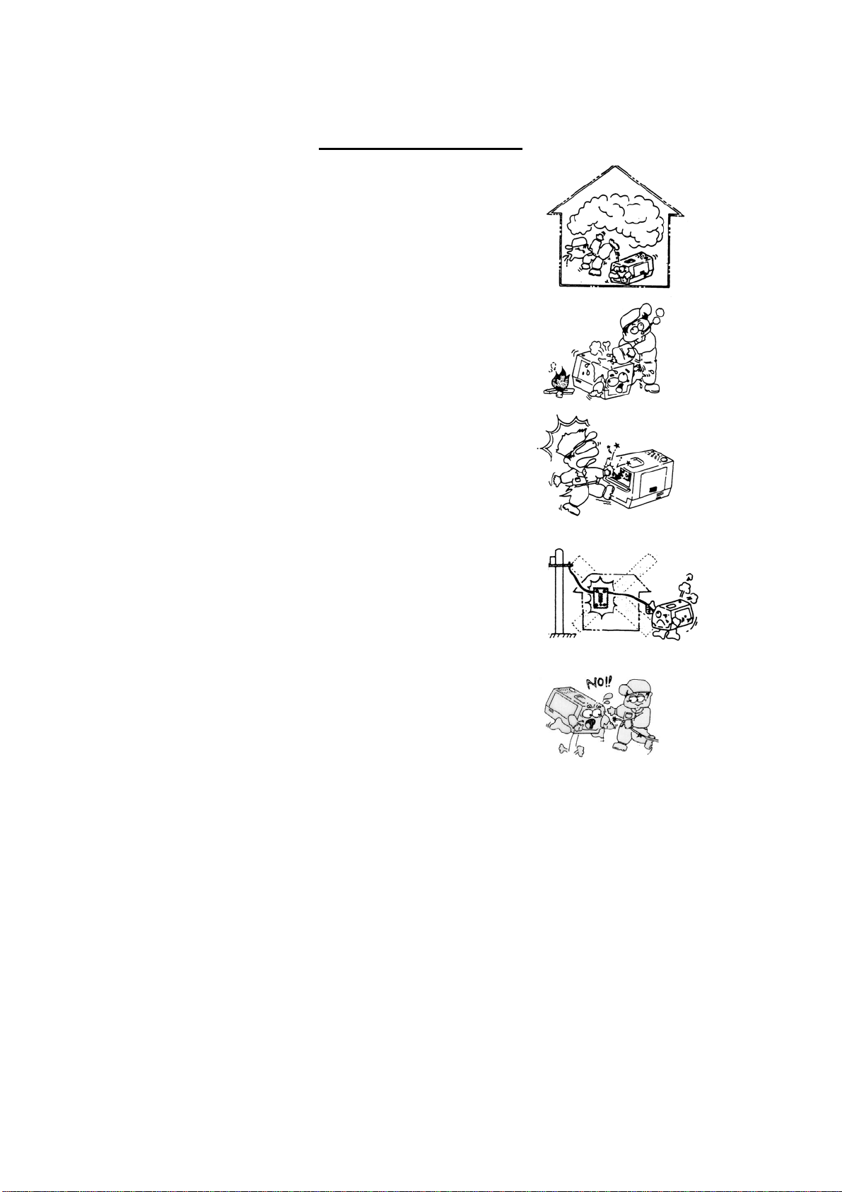
DURING OPERATION
Do not open any of the following items while the generator
is running and immediately after the generator has stopped.
1. Radiator Cap
Only perform these checks when the engine is cold to
avoid injury. Do not at anytime, when the engine is still
hot, remove the radiator cap. Opening the radiator cap
when the engine is hot will result in boiling water gushing
out of the radiator which will scald people nearby.
2. Cooling Water Drain Plug
Opening the cooling water drain plug when the engine is hot will result in boiling water
gushing out of the engine which will scald nearby people.
3. Engine Oil Drain Plug
Opening the engine oil drain plug when the engine is still hot will result in burning oil
gushing out of the engine which will scald nearby people.
4. Do not touch while operating the generating set, the engine cooling fan or any other
places of high temperatures like, the exhaust pipe, engine and radiator. Even when
the machine is stopped, take care that the machine has cooled down enough before
touching the engine and other components.
CAUTION:
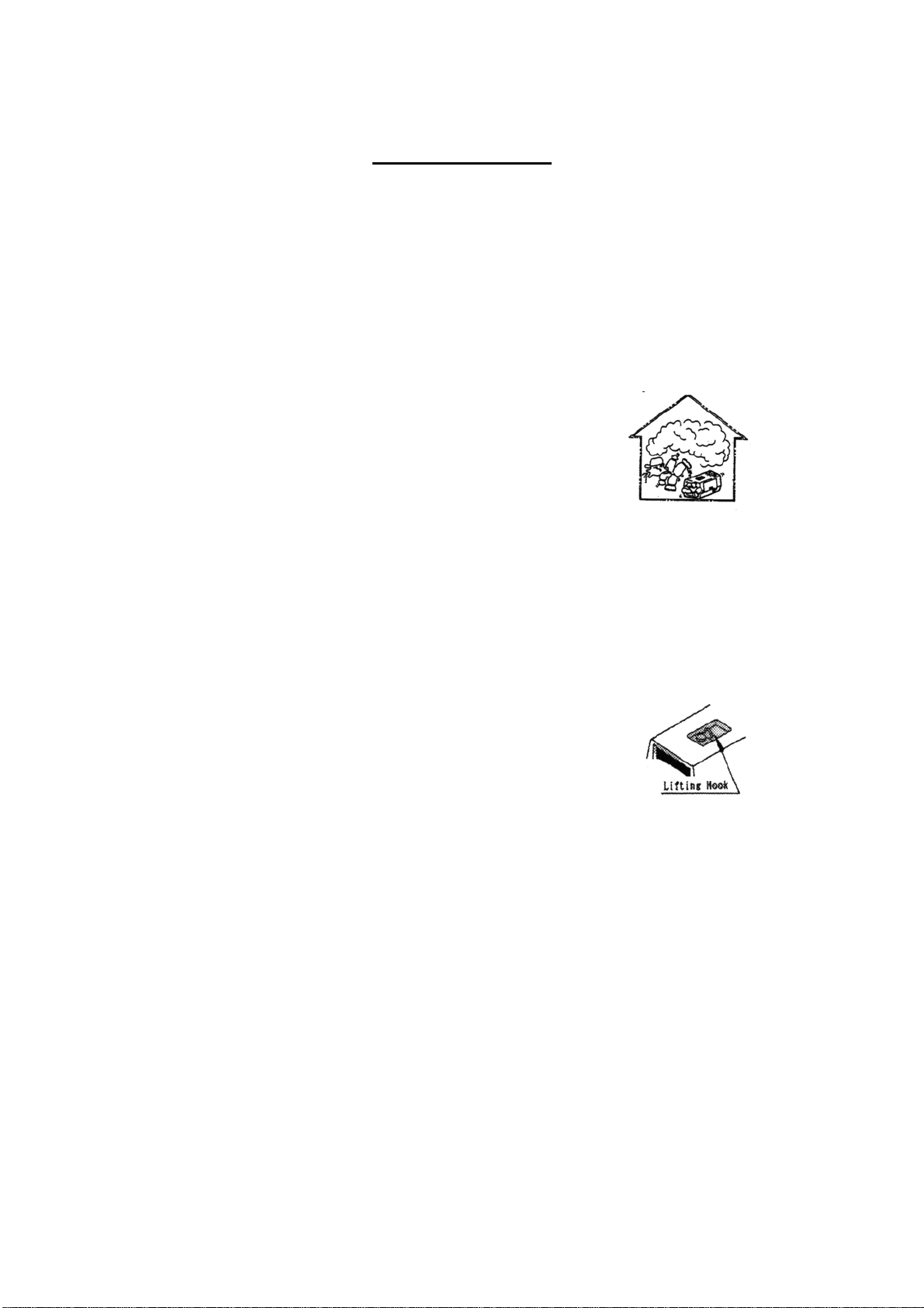
Battery
As the battery contains combustible gas, take extreme care in handling the battery. If
you are careless, like dropping the battery, there is a risk that the battery might explode.
In carrying out maintenance or inspection check, recharging and using booster cables,
extreme care should be taken to ensure safety.
CAUTION:
Strictly prohibited
Do not expose the battery to naked flames, sparks, cigarettes, and anything else
flammable, as the battery contains flammable liquid and gas.
CAUTION:
There is a risk of explosion if you do not charge the battery as there will be a build up
of combustible gas. The recharging process and handling of the battery should be done
in an area that is exposed to an air current, to avoid the risk of a dangerous concentration
combustible gas.
CAUTION:
In case the battery liquid is (dilute sulphuric acid) happens to come into contact with clothing
or skin, you must immediately rinse it out by using a lot of water. If the battery liquid comes
into contact with your eyes, wash it out with lots of water and seek medical attention
immediately.
6