Arcomed Volumed uVP7000 Premium User manual

!
Edition 04/16

Displays and control elements
Volumed® µVP7000 front view
Volumed® µVP7000 rear view

SH-7000-Pre-E-04/16
2
Index numbers
Keys:
1 On/Off
2 Start/Stop
3 Bolus / ESC
4 Menu / Select
5 Rate
6 Volume
Display elements:
7 Rate window
8 Volume window
9 Information window
10 Alarm window
11 LCD
Important mechanical parts:
12 Door
13 Door handle
14 Tube guides
15 Stop flow mechanism (here: Robson clamp, the other option is internal)
16 Air in line detector
17 Pressure sensor
18 Peristaltic mechanism
19 Easy Clip, empty bag detector
Infusion set:
20 Tubing
21 Drip chamber
22 Robson clamp
Connectors and handling devices:
23 Mains supply socket
24 Fuse
25 IR Interface
26 Nurse Call Connector
27 Connector for Easy Clip
28 Optional external Power Supply (12 to 15 Volt AC / DC)
29 Pole Clamp
30 Carrying handle

SH-7000-Pre-E-04/16
3
Table&of&Contents&
&
&
1!TECHNICAL DESCRIPTION................................................................................................... 4!
Control: ....................................................................................................................................4!
Power Supply:..........................................................................................................................4!
Software: ..................................................................................................................................5!
Specifications, instructions for use, warranty, performance data, EMC behaviour: ...............5!
2!SETUP MODE: ............................................................................................................................6!
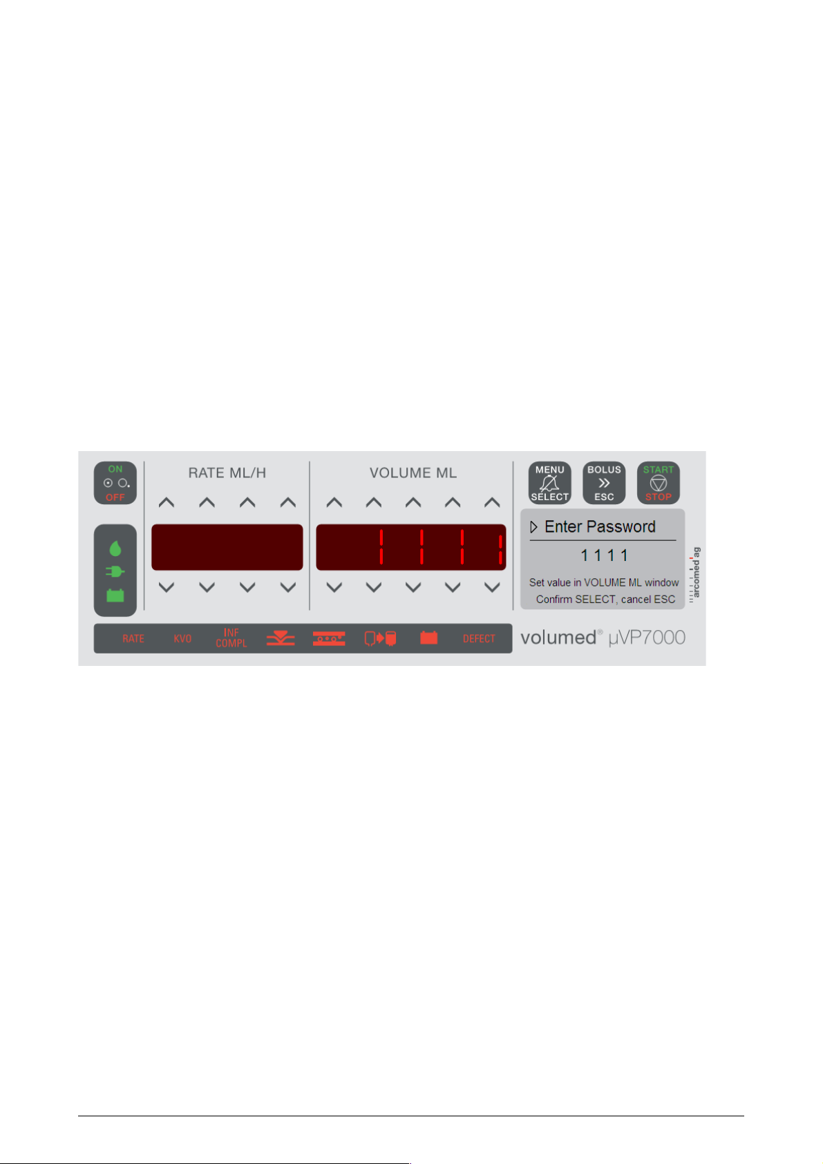
2.1!STARTING THE PUMP IN SETUP MODE ......................................................................................6!
2.2!DESCRIPTION OF PUMP SETUP...................................................................................................6!
2.3!BASIC SETTINGS.......................................................................................................................7!
2.4!OPTIONAL SETTINGS ................................................................................................................8!
3!TROUBLE SHOOTING ...........................................................................................................10!
4!DEFECT ALARMS ...................................................................................................................14!
4.1!MEANING OF ERROR CODES: ..................................................................................................15!
4.2!WATCH-DOG ON MAINPCB:...................................................................................................17!
5!REPAIRS .................................................................................................................................... 18!
5.1!REPLACEMENT OF MAIN PCB................................................................................................18!
5.2!DISMANTLING THE DOOR.......................................................................................................20!
5.3!CHANGING DISPLAY PCB AND FRONT FOIL ..........................................................................22!
5.4!DISMANTLE THE PUMP BLOCK ...............................................................................................24!
5.5!REPLACEMENT OF PRESSURE SENSOR ....................................................................................25!
5.6!REPLACEMENT OF UPSTREAM OCCLUSION PRESSURE SENSOR ..............................................26!
5.7!REPLACEMENT OF STOP-FLOW MECHANISM ..........................................................................28!
5.8!REPLACING THE PERISTALTIC COVER ....................................................................................32!
5.9!REPLACEMENT OF PB BACK PLATE AND SPRINGS .................................................................34!
5.10!CHANGING THE AIR DETECTOR PLATES...............................................................................35!
5.10.1!Part A: Door Air Detector Plate: ..................................................................................35!
5.10.2!Part B: Front Housing Air Detector Plate.....................................................................36!
5.11!ADDITIONAL OPTIONS AND AMENDMENTS ...........................................................................37!
5.11.1!Stop flow counter plate ..................................................................................................37!
6!INITIALISATION AND UPDATES........................................................................................ 38!
6.1!RELEASE NOTE ......................................................................................................................38!
6.2!SW UPDATE...........................................................................................................................39!
6.3!SW UPDATE AFTER REPLACEMENT OF DISPLAY PCB..............................................................40!
6.4!SW UPDATE AFTER REPLACEMENT OF MAIN PCB. .................................................................41!
7!CALIBRATION ......................................................................................................................... 43!
7.3!DOOR PRESSURE ....................................................................................................................47!
8!MAINTENANCE ....................................................................................................................... 48!
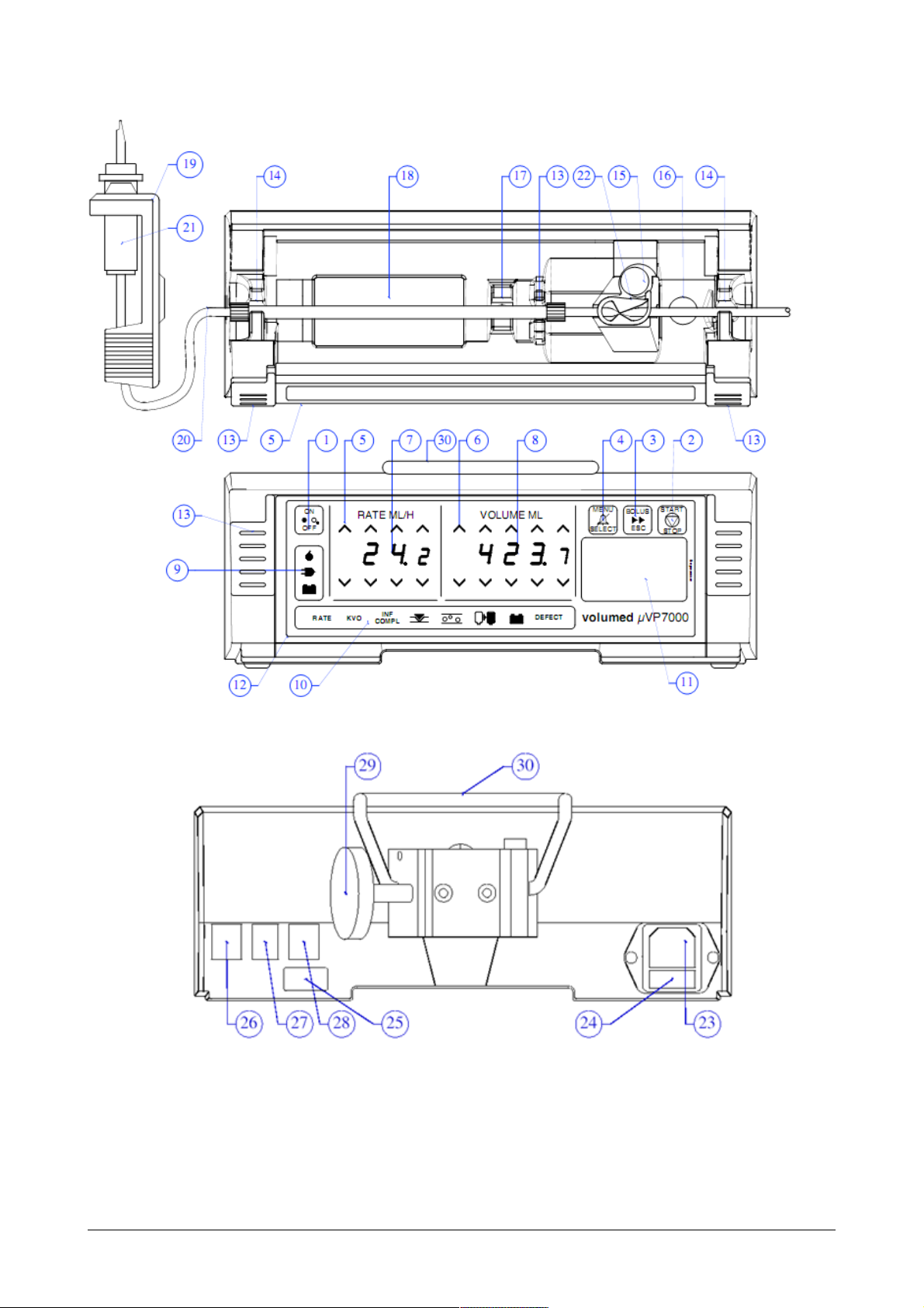
9!DRAWINGS AND LAYOUTS .................................................................................................51!
10!HISTORY ................................................................................................................................. 52!
&

SH-7000-Pre-E-04/16
4
1Technical description
Control:
The microprocessor controlled Volumed® µVP7000 is a peristaltic driven infusion pump
and intelligent software monitoring of all critical functions. The stepper motor transfers
movement to a drive belt, which is directly connected to the finger peristaltic mechanism.
All important infusion parameter are displayed on very well readable LCD and LED
displays. Entering parameters is done via a touch field.
The pump uses two independent microprocessors mutually checking each other. In case
of a discrepancy, the pump is stopped immediately and an acoustic alarm is emitted.
To achieve the accuracy stated in the specifications, the pump must be calibrated to the
used infusion set.
Power Supply:
A switching power supply directly mounted on the main PCB allows a wide input range of
110 – 230V AC, 50 - 60 Hz while a regulated 15V DC output.
Furthermore two DC-DC converters are used to provide the 5V and 3.3V power. On the
primary inlet the pump is fused. When changing the fuse, follow these instructions:
!!CAUTHION!!:
-Before changing a blown fuse, find out the reason why it is blown.
-Only carry out repairs when device is powered off and disconnected from mains.
-Take note of warning signs!
In addition to the switching power supply, an internal battery enables the user to use the
pump independently from mains supply. The battery is a NiMH Battery (9,6V, 2150 mAh,
Part No. 71160) and is always being charged when the pump is plugged into mains. The
battery is charged on a cyclic basis, which ensures a long battery life. A complete charge
is complete within approximately 10 hours. Then the charging is set to trickle charge, to
guarantee the battery will not self-discharge on mains. To monitor the charging a counter
is used. A battery empty alarm is triggered if either the counter or the measured voltage
falls below a certain value.
Sensors:
The pump uses several sensors to monitor its functions.
The air in line sensor consists of two opposite placed ultrasonic sound producing piezo
crystals. One is the transmitter, the other is the receiver. Ultrasonic waves are transmitted
in with liquid filled tubing much better than in empty tubing. This allows to determine, if air
or liquid is inside the tube. The air in line detector has the same accuracy at every flow
rate.
The pressure is measured on the outside of the tubing. Depending on the pressure within
the IV-line, the tubing acts with a certain force on the pressure sensor. This force is
measured and used for calculation of the pressure inside the system. The pressure sensor
requires a mechanical and electrical calibration (mbar).

SH-7000-Pre-E-04/16
5
The Easy Clip functions as a drop counter and is fastened to the drip chamber. Drops are
detected via light barrier in the Easy Clip. The Volumed®µVP7000 is not regulated
through the drop count, the Easy Clip serves as an additional safety feature allowing to
detect reverse flow, free flow, upstream occlusion or an empty bag.
Using a hall sensor the rotation of the peristaltic system is monitored. If the measured
speed does not correspond to the set rate, the pump is stopped and an acoustic alarm is
emitted. This allows checking the mechanical and electrical functioning of the peristaltic
system.
All verification tests were performed with the IV sets Volumed®Set Standard APPF512
and the Volumed®Set silicon APSF227.
Software:
The microcontrollers are equipped with an internal flash memory (256/512kB). For
software updates and data transfer the Volumed® µVP7000 is equipped with infrared
interfaces. This enables to carry out these updates without having to open the housing.
The required USB interface (Part No: 5316) and arcomed ag’s own PremiumLink™
software are compatible with all common Window operating systems.
!!WARNING!!:
The Volumed®µVP7000 is turned completely off during a software update to access the
internal flash memories. At this stage any false manipulation may cause pump failures. It is
of utmost importance that only trained personnel carry out updates because there are
several variations of carrying out updates. arcomed ag is not responsible for pump
damages because of false handling. There is no physical damage done to the pumps, but
the processors need to be reinitialized. Only arcomed ag may carry out the task of re-
initialisation. Furthermore are updates only to be carried out by trained personnel.
Specifications, instructions for use, warranty, performance data, EMC behaviour:
The specifications, instructions for use, warranty conditions, performance data and EMC
behaviour can be found in the user manual.
Interval Preventive Maintenance
Preventive maintenance (PPM) have to be carried out at least every 24 months or 10’000
work hours. All devices have to be checked according to the user manual chapter 8. Only
trained and certified persons may carry out preventive maintenance on the devices.
Uncertified persons are not authorized to carry out preventive maintenance or carry out
repairs to the product. Damages caused by handling of not certified person do not fall
under any warranty.
Maintenance and safety checks have to be done according to the checklist in the user- and
service manual.
Worn or defective parts must be replaced. However, the pumps do not need any regular
replacement of specific items. Arcomed AG provides service kits and it might be more
efficient to use all parts provided in the kits to avoid additional repairs. It is however not
mandatory to use all parts in the kits.

SH-7000-Pre-E-04/16
6
2Setup Mode:
To carry out calibrations, adjustments or data transfers, the pump has to be started in
setup mode. In the following chapter this process is described in detail.
2.1 Starting the pump in Setup Mode
1. press and hold right down arrow “V” key on the “VOLUME ML” window
2. press “ON/OFF”
3. enter 1111 in the “VOLUME ML” window with the arrow “V / Λ”keys
4. confirm with “MENU/SELECT”
5. “RATE ML/H” and “VOLUME ML” window show 0
You have now successfully entered the setup mode of the Volumed® µVP7000. The
address number is displayed in the “RATE ML/H” window. In the “VOLUME ML” window
the current values on the corresponding address is shown. The values can be changed
with the arrow “V / Λ” keys.
Figure: Entering the password for Setup Mode (1111)
Each parameter and its functionality are described in the chapters 2.3 and 2.4.
2.2 Description of pump setup.
The database of the pump consists of approximately 55 addresses. They consist of the
following groups:
Address 0-19 = Basic settings, calibration
Address 20-55 = Optional settings
Basic settings are superior parameters, which define the actual over all calibration of the
device. With the optional settings the LCD contrast or the language etc. can be changed.
Manual changes on the option settings are only possible when address 50 = 0. The
optional setting for each configuration can only be changed with arcomed ag own
PremiumLink™ software. For the usage of PremiumLink™ separate trainings are highly
recommended. Please contact arcomed ag for further details.

SH-7000-Pre-E-04/16
7
!!IMPORTANT!!:
To ensure that the basic settings take effect, set address 50 = 0!
Optional settings have to be programmed with the PremiumLink™ SW!
Ensure that after maintenance the configuration on address 50 = 1-8.
2.3 Basic Settings
Address
Description
Default
0
9999: Re-initialisation (by replacing main PCB) thereafter it
is mandatory to recalibrate the pump.
0
1
9999: copy setup from display to mains.
-
2
9999: copy setup from mains to display.
3
Enter update codes. Step 1: Update ID 1: STD, 2: DCA, 3:
PCA, 4: TCI, 5: RAM, 6: TOC, 7: PIB, confirm with select.
Step2: send the upgrade code, update ID and displayed
code to Arcomed, do not switch off device until step 3 is
completed. Step 3: enter the ugrade password supplied from
Arcomed and confirm with select.
9
LCD Contrast: allows adjusting the LCD contrast setting, try
to increase or decrease last digit first.
354
10
Speed correction, see volume test
*
11
Rate tuning, allows to fine tune the speed depending on the
rate. Internal setting.
0
12
Upstream pressure sensor trigger level, only available if an
upstream sensor is installed. If installed, normally set to 70,
otherwise set to 0 to disable.
*
13
Long time correction LTC, PVC = 2010, Silicon =
deactivated. Allows to fine tune speed for long term
infusions. Internal setting.
2010
15
Gain of pressure transducer (see pressure calibration)
*
16
Offset of pressure transducer when door is closed with IV
set (see pressure calibration)
*
17
Limit pressure if door closed without IV set (see pressure
calibration)
*
18
Stop Flow
14 – 18: Internal Stop Flow
114 – 118: Robson Stop Flow
15
19
Motor torque. Internal setting
230

SH-7000-Pre-E-04/16
8
2.4 Optional Settings
This settings can be adjusted over PremiumLink™. For quick checks, the values on
address 50 = 0 can be changed.
NOTE: Do not forget to put back the default-settings.
Address
Description
Default
20
Backlight on mains, 4099 = 40% night 21h-7h, 99% day
4099
21
Backlight on battery, 4070 = 40% night 21h-7h, 70% day
4070
22
Near empty alarm in seconds. Triggers pre-alarm VTBI is
reached.
0
23
Stand by delay in seconds. If the pump is left stopped, a
reminder alarm will be triggered after the stand by delay.
240
24
Acoustic alarm, ex: 3569: 3: pitch height of the sound, 5 *
100 ms interval between alarm beeps, 6: acoustic volume
for key beep, 9: acoustic volume for alarms.
3569
25
Preset Bolus rate in ml/h, internally limited to: PVC 999.9
ml/h, Silicone: 1200 ml/h
1200
26
Max. Bolus volume in ml. The volume for an automatic bolus
can’t exceed this value.
10
27
Max. Rate in ml/h. Absolute max rate of the pump including
rate during bolus applications. Internally limited to: PVC
999.9 ml/h, Silicone: 1200 ml/h
1200
28
KVO rate in 0.01 ml/h, max. value 10ml/h
300
30
0: IV-Set PVC
1: IV-Set Silicon
2: Low Volume (rate limited to 700 ml/h, Adr. 10 adjustable
to 750)
*
34
Language
0: first language, 1: second language
0
35
PCA Password (access to PCA parameters)
1001
36
Pressure limit (default pressure limit)
600
37
Max. Pressure limit (maximum pressure limit)
1000
40
Air limit in µl to trigger an air alarm (50 to 250µl)
150
41
Cumulated air bubble in µl over 15min to trigger an air alarm
1000
50
Configuration (0: internal setup from setup mode, 1-8
external configuration downloaded through the interface)
1
51
Production date (year, month)
*
52
Production number (serial number)
*

SH-7000-Pre-E-04/16
9
How to apply Optional Settings:
Optional settings are adjusted via PremiumLink™ where options can be easily selected.
Further the configuration via PremiumLink™ ensures a configuration consistency thus
increasing patient safety.

SH-7000-Pre-E-04/16
10
3Trouble shooting
Fault
Cause
Action
Over Infusion
Incorrect giving set
Use Arcomed approved set
Speed tuning requires adjustment
Adjust Speed tuning (address 10)
Wrong set selection (in VP7000
silicone is PVC selected)
Select correct IV brand (address
30)
Worn peristaltic cover
Replace cover
Worn door hinge
Overhaul door
Under infusion
Incorrect giving set
Use Arcomed approved set
Speed tuning requires adjustment
Adjust Speed tuning (address 10)
Wrong set selection (in VP7000
PVC is silicone selected)
Select correct IV brand (address
30)
Worn out peristaltic cover
Replace cover
Worn out door hinge
Overhaul door
High
Occlusion
Incorrect giving set
Use Arcomed approved set
Pressure gain (address 15)
adjustment required
Adjust Pressure gain
Pressure Transducer requires
mechanical adjustment
Adjust transducer
Pressure Transducer damaged
Replace transducer
Low
Occlusion
Incorrect giving set
Use Arcomed approved set
Pressure gain (address 15)
adjustment required
Adjust Pressure gain
Worn door hinge
Overhaul door
Pressure Transducer requires
mechanical adjustment
Pressure Transducer requires
mechanical adjustment
Pressure Transducer damaged
Replace transducer
Will not power
up (on mains)
Blown fuses
Check and replace
Wire detached from mains socket
Reconnect
Display cable defect
Check and replace Display PCB
Transformer faulty
Check and replace main PCB
Fuse F1 defect
Replace Main PCB and send it to
Arcomed with comment that
probably F1 could be broken.
Warning: If F1 will be manually
replaced with a soldering gun,
warranty will be not given.

SH-7000-Pre-E-04/16
11
Fault
Cause
Action
Will not power
up (on battery
only)
Battery discharged
Recharge for 10 hours and check
Battery cell damage
Replace battery
Display cable defective
Replace Display PCB
Fuse F2 defect
Reconnect battery, Check battery
fuse F2 on main PCB – Replace
PCB.
Warning: If F2 will be manually
replaced with a soldering gun,
warranty will be not given.
Pump will not
charge
Battery fuse defective
Replace battery fuse F2 on main
PCB
Defective battery cell
Replace battery
Door open
alarm even
when door is
shut
Magnet in door handle moulding
missing.
Replace magnet.
Magnet in door latch mounted the
wrong way
Turn around magnet
Hall transistor on front PCB out of
alignment
Align hall PCB.
Hall transistor faulty.
Replace front PCB.
Frequent Air-in
Line alarm
Ultrasonic faces of detector dirty or
scratched
Clean with soft tissue or cotton bud
Faulty detector plates.
Replace detector
Fluids containing excessive
amounts of air
Contact Arcomed representative
AIL adapter not positioned properly
Replace and realign AIL adapter
Display cable defect
Replace Display PCB
Front PCB defect
Replace front PCB.
Op amp on display PCB defect
Replace Display PCB

SH-7000-Pre-E-04/16
12
Frequent
Empty bag
alarm
Connector detached from rear port
Reconnect
Easy Clip not on right drip
chamber
Mount Easy Clip to correct drip
chamber
Easy Clip fogged
Shake Easy Clip to "clean" drip
chamber
Easy Clip dirty
Clean Easy Clip
Drip chamber too full
Fill to correct level (30 per cent)
Drip chamber and Easy Clip not
level
Mount Easy Clip level
Corrosion in pins
Clean and apply silicon
Liquid too viscous
Adjust drop limit (Address 33)
Faulty Empty Bag detector
Replace Easy Clip
Rear PCB not connected to Main
PCB
Plug in connector replace PCB
Fault
Cause
Action
Constant
occlusion error
during running
Incorrect giving set
Use Arcomed approved set
Pressure gain (address 15)
adjustment required
Adjust Pressure gain
Worn Peristaltic cover
Replace cover
Pressure transducer not connected
Plug in pressure sensor
Pressure Transducer requires
mechanical adjustment
Adjust transducer
Pressure Transducer damaged
Replace transducer
Stop Flow Test
always fails
Gear wheels of Stop Flow
Mechanism are broken
Replace Stop Flow Mechanism
Giving set not inserted correctly
Reinsert giving set
Stop Flow mechanism gears
tightened too much
Adjust torque of gears
Wrong giving set
Use correct giving set
Low quality infusion set
Move giving set 10 cm, use new
giving set
Address 18 set too low
Set address 18 to 14 (int.) or 114
(Robson)
Pressure Transducer requires
mechanical adjustment or is defect
Adjust or replace pressure
transducer
Battery voltage too low
Plug in mains
Air in giving set
Purge giving set
LCD displays
strange signs,
missing dot or
lines, blank
LCD
LCD glass broken, defective cable
to LCD
Replace display PCB and LCD
Language settings
Check address 34 and/or reload
pump text

SH-7000-Pre-E-04/16
13
Fault
Cause
Action
Ramping
pressure during
running
Pressure sensor defective
Replace pressure sensor
Pump turns itself
on and off when
opening the door
Display PCB defective
Replace Display PCB or display
cable
LEDs show
strange things
Display PCB defective
Replace Display PCB
Pump makes
clicking noise
(also in
combination with
F-3 error)
Thread in motor axis defect
Replace motor axis, tighten screws
motor axis
Bearing next to motor axis defect
Replace bearing
Drive belt too long
Replace drive belt
Drive belt worn out
Replace drive belt
IR interface not
responding,
pump above
not visible in
network
Protective plastic strip missing
from top IR
Replace protective strip
Interference top IR and mains
input
Make sure protective strip has
aluminium foil and foil touches
metal chassis.
Replace Main PCB with ‘EX’
transformer
Receiver/transmitter on Main PCB
defective
Replace Main PCB
Drive belt worn out
Replace drive belt

SH-7000-Pre-E-04/16
14
4Defect Alarms
The Volumed® µVP7000 continuously monitors the correct functionality of the pump. For
safety reasons the pump will trigger a defect alarm if any discrepancy is detected. If an
internal alarm occurs, the pump will automatically stop and emit an audible alarm and the
alarm pictogram is illuminated. An internal alarm does not mean that the pump is defect,
but it should be carefully checked before putting it back into operation.
HINT: Take the pump of the mains power. You can switch off the pump after an internal
alarm by pressing the “ON/OFF” key. If the pump should not power down immediately and
continue the audible alarm, hold the “ON/OFF” key of 12 seconds to reset it. A reset will
not erase the configuration of the pump. However the current infusion settings might be
lost.
In the “Status / Help” menu, which can be accessed with the “MENU/SELECT” key, the
LCD will display the error code. In such cases the pump must not be used any more until
the cause has been checked. If the device cannot be repaired the pump should be sent to
technical department or to arcomed ag.
Note:
On the LITE pumps the defect codes can be viewed in the history file. To retrieve
the history file a read back needs to be carried out.

SH-7000-Pre-E-04/16
15
4.1 Meaning of error codes:
Code
Meaning
Cause
Measure
F-00
Communication
error between
processors
Different Software
on Display PCB and
Main PCB
Complete SW update
Main PCB defect
Replace Main PCB
Display PCB defect
Replace Display PCB
Display cable loose
Fix display cable
F-01
Air detector
check
Air detector plate
broken
Replace air detector plate
Front PCB broken
Replace Front PCB
Display PCB broken
Replace Display PCB
F-03
Motor too slow
(Hall counter
check)
Hall sensor defect.
Replace Hall PCB
PCB Motor driver
defect.
Replace Main PCB
Stepper motor
defect
Replace stepper motor
Pump block not
greased well
Clean peristaltic mechanism and
reapply grease
Hall PCB not
connected properly
Check Hall PCB connector on Hall
PCB and Main PCB
Screw motor axis
loose
Tighten screw motor axis
Motor axis defect
Replace motor axis
Magnet in crown
gear lost
Replace magnet
F-05
Motor too slow
(Volume counter
check)
SW Problem
SW update necessary
Main PCB defect
Replace Main PCB
F-06
Motor too fast
(Volume counter
check)
SW Problem
SW update necessary
Main PCB defect
Replace Main PCB
F-07
Key stuck
Display PCB defect
Problem
Replace Display PCB
If any key is
pressed more than
Open pump and unplug battery
cables.

SH-7000-Pre-E-04/16
16
Code
Meaning
Cause
Measure
1min. The
Microprocessor
detected the key as
defect and will give
a “Defect”-Alarm.
Display PCB is not
mounted properly
Mount Display PCB properly
F-09
CRC - Error
SW not loaded
correctly
Make SW update
F-10
Transmit check
Internal
transmission check
If persistent, check cable main
PCB and display PCB, replace if
necessary
F-11
CRC – Error
Initial CRC check,
transmission check
If at start up: Init Setup, SW
update, restart, if during operation
and persistent: check cable main
PCB and display PCB, replace if
necessary
F-12, 13
Timing check
Internal timing failed
If persistent, replace main or
display PCB
F-18
Clutch check
(6000)
Safety check clutch,
DC driver defect
6000 only: If persistent: Replace
main PCB
F-20
CRC – Error
SW problem:
Configuration
Reload Configuration
F-21
Revision Check
Error
SW Release and
Configuration do
not match
Reload SW and Corresponding
Configuration
F-22
CRC-Error
SW problem: pump
text
Reload Pump Text
F-23
Revision Check
Error
SW Release, text
do not match
Reload SW and pump text.
F-24
CRC Error
SW problem: Drug
mode
Reload SW and corresponding
drug mode.
F-25
Revision Check
Error
SW Release, Drug
mode do not match
Reload SW and corresponding
drug mode.

SH-7000-Pre-E-04/16
17
4.2 watch-dog on MainPCB:
On the MainPCB (Version 150305/mvo or later) arcomed implemented a watch-dog
to recognize a loss of the battery (during operation on battery-mode) or an unlikely error in
the main-processor on the MainPCB. In the rare case of one of these situations, there will
be an alarm. This alarm is always set as a “beep melody” and can not be changed.
Disconnect the battery, only 60 seconds after the pump has been powered and switched
off.
To reset the alarm, the battery should be reconnected to the MainPCB or a defective
battery must be replaced. Connecting the pump on mains resets this alarm, however the
battery and connection must be checked.
During updates over PremiumLink™ it can also be, that this alarm accurse for a few
seconds due to the restart of the microprocessor.

SH-7000-Pre-E-04/16
18
5Repairs
The Volumed® µVP7000 Premium may only be serviced by arcomed ag or through
arcomed ag trained and licensed personnel.
In warranty cases please refer to chapter 6 in the user manual.
Please check also chapter 5.11 for additional options that might be installed in your device.
!!WARNING!!:
The device must be disconnected from mains power prior to any repairs on the device.
The acoustic sounder can exceed 100 dB when the housing is open. Cover it or keep
sufficient distance to your ears before switching on the device with an open housing.
5.1 Replacement of Main PCB
Tools & recommended spare parts:
- Antistatic work place
- 2.5 mm Hex driver
- Main PCB programmed µVP7000 Premium (76235)
Procedure:
1.
Turn off pump and unplug from mains
Remove Pole Clamp (2x 2.5mm Hex screws)
2.
Unplug rear connector and the mains cable from the rear power plug
Rear connector
Rear power
plug

SH-7000-Pre-E-04/16
19
3.
Remove four 2.5 mm Hex screws
4.
Remove connectors of:
Stepper motor (1), DC motor (2), Display print (door) (3), Battery (4) and Front PCB
(5).
5.
Fitting new main PCB
Reassemble pump in reverse order
Note:
Plug in connector correctly, (see connector pin and hole on the main board)
6.
Update the pump following the instructions on chapter 6.4
(1)
(2)
(3)
(4)
(5)
Other manuals for Volumed uVP7000 Premium
2
Table of contents
Other Arcomed Water Pump manuals
Popular Water Pump manuals by other brands

Stancor
Stancor AHS Series Installation, operation and maintenance manual

Interpump Group
Interpump Group QUIKY TURBO 11.50 operating instructions

Teral
Teral ASVM Series instruction manual

SPX
SPX Johnson Pump TopLobe TL1 instruction manual

PYD Electrobombas
PYD Electrobombas PC 32 8 220 instruction manual

SCOPREGA
SCOPREGA GM 6 manual

Cosmo
Cosmo CPB Installation and operating instructions

Graco
Graco Husky 15120 repair parts

Allfett
Allfett ALL-5 AC INTRODUCTION AND USER MANUAL

Glasswelt
Glasswelt GARLAND GEISER 653 QG instruction manual

SPETEC
SPETEC Perimax 12 user guide

Kremlin-Rexson
Kremlin-Rexson airmix OPERATING PRINCIPLE AND START-UP