Arconas Place User manual


Oct 2021 (rev 14) 2 arconas.com
General
This process describes how to assemble a linear Place unit. The process canbe performed safely
by two people of normal strength.
Fully Assembled Views
3 Seat Unit with Armrest Shown

Oct 2021 (rev 14) 3 arconas.com
Tools Required
1. Rubber Mallet
2. Cordless Drill
3. 5/16-18 Tap to clean tapped holes if necessary
4. 1/4-20 Tap to clean tapped holes if necessary
5. Awl for positioning holes if necessary
6. 5/32 Hex Key
7. 3/16 Hex Key
8. 1/4 Hex Key
9. 7/64 Hex Key
10. 3/32 Hex Key
Part List
Part Description
Part Picture
Beam
Leg Casting
Arm Casting

Oct 2021 (rev 14) 4 arconas.com
Bushing
Back to Back
Connector
Armrest
Tablet
Drink Holder

Oct 2021 (rev 14) 5 arconas.com
Hanger Casting
Cover Plate (for no
Power)
Power Pod
Seat Cushion

Oct 2021 (rev 14) 6 arconas.com
Back Cushion
Cast Clip
Glide
Retention Clip (For 2
Seater ONLY)

Oct 2021 (rev 14) 7 arconas.com
Hardware List
Part Number
Part Description
Part Picture
Where to use?
H002
1/4-20 x3/4” Button Head Socket Cap
Screw Black
Armrest/ Tablet to arm casting;
H506
1/4-20 x 1” Button Head Socket Cap
Screw Black Loctite
Hanger bracket to seat and back;
Cast clip to hanger bracket;
Retention clip to hanger bracket;
H507
5/16-18 x 1” Button Head Socket Cap
Screw Black Loctite
Cast clip to beam;
H029
5/16-18 x 3/4” Flat Head Socket
Screw
Power cover plate to beam;
H067
1/4-20 Countersunk Tooth Locker
Washer
Armrest/ Tablet to arm casting;
H124
5/16-18 x 1 ¼ Socket Head Cap
Screw
Arm casting to beam;
Power cover hub to beam;
H560
5/16-18 x 3/4” Button Head Socket
Screw Black with Loctite
Legs to beam;
H142
#8-32 x 3/4” Flat Head Socket Screw
Power cover plate to beam;
H217
5/16-18 x 5/8” Button Head Socket
Screw
P-clip to beam;
H238
5/16 High Collar Split Lock Washer
Arm casting to beam;
Power cover hub to beam;
H128
5/16-18 x 1/2" Button Head Socket
Cap Screw SS
(for 2-seater only)
Retention clip to beam(2 seater
only);
H561
5/16-18 x 7/8" Button Head Socket
Cap Screw Black with Loctite
(for back to back unit only)
Legs and back to back connector
to beam;
H105
#10-24 x 3/4 in Flat Head Socket
Cap Screw BLK
Arm rest to arm casting;
H088
1/4-20 x 3/4 in Flat Head Socket Cap
Screw BLK
Tablet to arm casting;
H117
5/16in Countersunk External Tooth
Lock Washer
Power cover plate to beam;

Oct 2021 (rev 14) 8 arconas.com
Please Note: Arconas does not provide floor mounting hardware. Arconas recommends
consulting with building owner before installing any anchors to the floor.
Tips
•Assemble on a sturdy table set at comfortable height
•Table should be covered by a soft cloth or other material
•Hand-start all screws and finish with hand tool
•DO NOT USE A TORX BIT ON ANY OF THE FASTENERS
•Do not use a hard faced hammer on any part
•Layout all parts ahead of time to ensure you have everything
Assembly Process
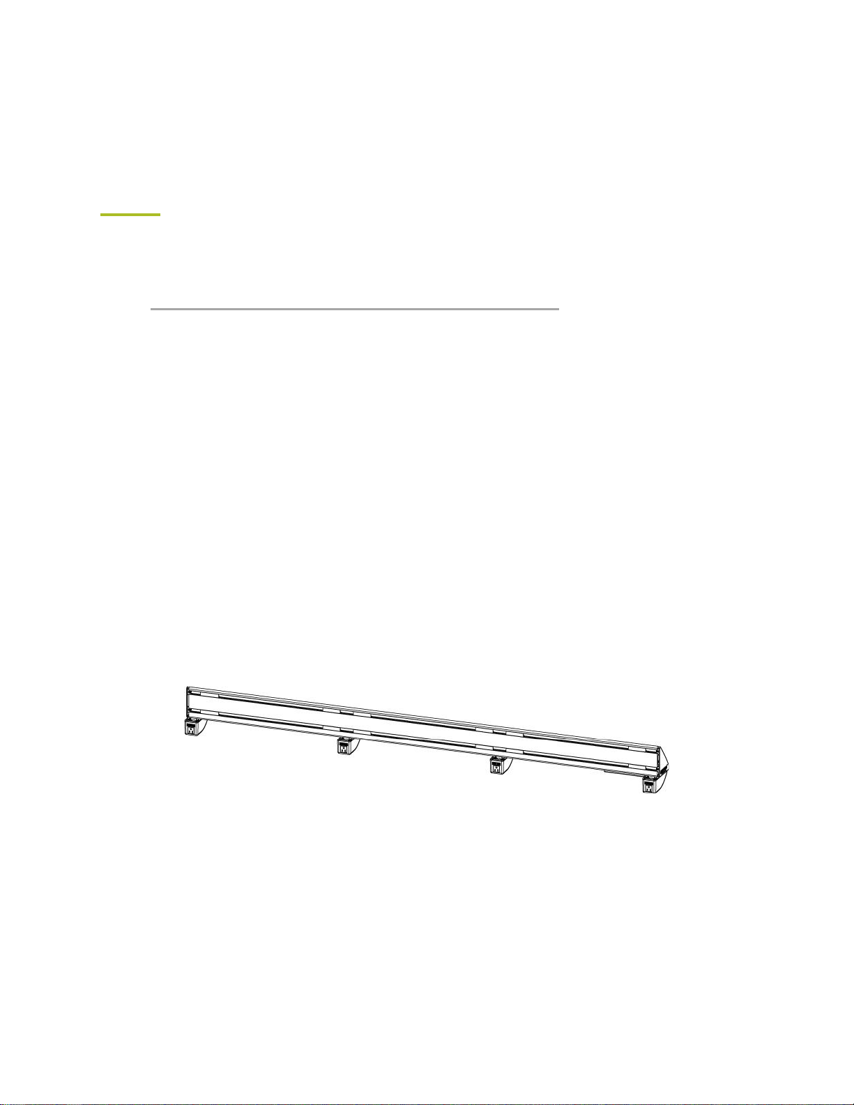
1. The Main Place beams will be shipped partially assembled. They will include the nuts
used to connect the arms, legs and seat brackets (within the mounting grooves), groove
fillers, end caps and power pods. If the unit is to be equipped with power outlets, the
beam will also include the inlet assembly, outlet assembly, raceway fillers, wire
management devices and wiring. Consult a floor plan and select a beam of the correct
length for the unit to be assembled. See the table below. Note that an intermediate table
takes the space of one seat.
Number of Seats
Length with Armrest
Length with Tablet
2
48.75” (1238 mm)
55.25” (1403 mm)
3
72.00” (1829 mm)
81.75” (2076 mm)
4
95.25” (2419 mm)
108.25” (2750 mm)
5
118.5” (3010 mm)
134.75” (3423 mm)
Step 1 - Partially Assembled Beam (Include fastening nuts, groove fillers, end caps, power pods, inlet assembly,
outlet assembly, raceway fillers and wiring)

Oct 2021 (rev 14) 9 arconas.com
2. Install a Leg near each end of the beam. It is recommended that this process to be done
with the beam lying flat on the ground. A soft cloth sheet should be placed underneath
the beam to protect the unit from scratches and dents. Use H560 5/16-18 x3/4” button
head socket screw with Loctite attached to the nuts in the bottom grooves of the
beam. Loosely attach cast clips on to respective nuts under the beam.
Step 2.1 - Installation of Leg

Oct 2021 (rev 14) 10 arconas.com
3. Attach the back cushions to two cast aluminum hanger brackets using four H506 1/4-20
x 1”socket button head screws with Loctite. Attach a seat cushion to the hanger
brackets using four more of the same screws. Use awl to help align with hole. Be careful
not to poke thought cushion. Loosely attach all 8 screws before tightening.
Step 3 - Assembly of Seat and Back
4. Position each seat and back assembly midway between the arms. Lift the assembly to
guide the top surface of the hooks on the back of the hanger brackets into the grooves
on the front of the beam. Press the hooks into the grooves and pull down to engage the
hooks in the beam.
Step 4 - Install the Assembled Seat to the Beam

Oct 2021 (rev 14) 11 arconas.com
5. Attach each hanger bracket to the beam aligning them with the cast clips. Loosely
fasten the H506 1/4-20 x 1”socket button head screw (see 5.1) into the smaller hole
in the cast clip. Then tighten the H507 5/16-18 x 1”socket button head screw with
Loctite. (See 5.2)
Notes:
For 2-seater unit, retention clip will replace cast clips at both ends because leg will be
installed at the ends. At the meantime, H506 and H128 will be used to fasten retention
clip. Therefore step 5.1 and 5.2 should be replaced by the following 5.3, 5.4 and 5.5.
Exploded view is shown(see5.3) for the parts and hardware to be installed. Loosely
fasten H506 1/4-20 x 1”socket button head screw (see 5.4) into the smaller hole of
cast clip and retention clip. Then tighten the H507 5/16-18 x 1”socket button head
screw with Loctite and H128 5/16-18 x 1/2” socket button head screw stainless
steel for cast clip and retention clip, respectively (see 5.5).
Hanger Bracket
5.1
5.1
Cast Clip
5.2
5.2

Oct 2021 (rev 14) 12 arconas.com

Oct 2021 (rev 14) 13 arconas.com
6. Repeat until all seat/back assemblies are attached.
7. Install armrests or tablets on the arm castings as required. Place the keyway slots of
the armrest over the screws H105 10-24 x 3/4 in Flat Socket Cap Screw and pull
forward (for tablet, H088 1/4-20 x 3/4 in Flat Head Socket Cap Screw BLK will be
used). If necessary, adjust the screws higher or lower to ensure a firm fit between the
armrest/tablet to the arm casting. Attach the armrest or tablet in place with two H002
1/4-20 x 3/4” Button Head Socket Screws and H067 1/4 Countersunk Tooth Lock
Washer through the bottom of the arm casting. Repeat the installation until a snug fit is
achieved on all units.
STEP 7.1 -INSTALLATION OF ARMREST STEP 7.2 -INSTALLATION OF TABLET
A place arm can be replaced with an arm cover plate using H124 5/16-18 x 1 1/4” socket head cap screw.
A power pod can be replaced with a power cover plate.
STEP 7.3-INSTALLATION OF ARM &POWER COVERS

Oct 2021 (rev 14) 14 arconas.com
8. POWERED PLACE –Verify that the nuts for the arms are correctly positioned in the
front grooves of the beam. Loosen the screw at the back of the power pod that mates to
the beam, do not remove the pod. Align the arm’s bushings to the key slots on the top
face of the power pod. Once the arm is aligned with the power pod, attach the arms to
the beam using H124 - 5/16-18 x 1 1/4” socket head cap screws and H238 - 5/16"
High Collar Lock Washer. Ensure that the arm castings are vertical. Once the arm is
fastened, retighten the loose screw at the back of the power pod. Repeat process on all
arms.
Step 8 –Loosen screw at the back of the power pod. DO NOT remove power pod. Align the arm’s
bushings with the key slot on the power pod. Then fasten arm to beam.

Oct 2021 (rev 14) 15 arconas.com
9. NON-POWERED PLACE –Lay the beam on the floor so that the bottom edge faces
upward. A soft cloth sheet should rest underneath the unit to protect it from scratches
and dents. If no power is to be installed, attach power cover plates to each arm by
removing and re-using two H142 #8-32 x 3/4in flat head socket screws (see 9.2) and
one H029 5/16-18 x 3/4in Flat head Socket Cap screw with one H117 5/16in
Countersunk External Tooth Lock Washer (see 9.1). A 5/16-18 nut should be found in
the bottom rear groove of the beam.
Step 9 - Installation of Cover Plate in place of Power pod
10. Once all the components are installed, ensure all fasteners are tighten and all parts are
secured.
Step. 10 –3 Seat Unit Assembled
9.1
9.2

Oct 2021 (rev 14) 16 arconas.com
11. Use the provided layout as a guide for Place electrical configuration. For units that do
not require daisy chaining, insert the C13 power cords into the inlet. When the units
require daisy chaining, connect the adjacent units using the jumper cords (the C14
connector to the outlet on the power unit and C13 connector into the inlet on adjacent
unit). Once the units are connected, turn the circuit breaker (switch) to the “ON” position.
Ensure the blue lights are lit on each pod. If the pod fails to light up, contact Arconas for
support.
Do not daisy chain adjacent units. Only back to back units that are connected to
each other.
Do not plug C14 or C13 connectors into Power Pod (see Parts List) outlet.
FIG.11.1 –C13 POWER CORD
FIG.11.2 –C13 TO C14 JUMPER CORD

Oct 2021 (rev 14) 17 arconas.com
For Back to Back
For back-to-back configurations, we recommend sawhorses/work benches be used when
installing the back-to-back connectors. Use the sawhorses/work benches to elevate the units.
Employ an awl to position and align the back-to-back connectors between the legs and the
beam. Once aligned, use the provided hardware H561 5/16"-18, 7/8" HEX DR ROUND HEAD
SCREW WITH LOCTITE to fasten the legs and connectors to the beam. Repeat process on the
opposite end.
STEP 2.2 -INSTALLATION OF BACK-TO-BACK
Cable Management
Use cord springs to dress any excess cords. Insert cord spring into beam then twist clockwise
to engage prongs.

Oct 2021 (rev 14) 18 arconas.com
Ground Mounting
Please Note: Arconas does not provide floor mounting hardware. Arconas recommends
consulting with building owner before installing any anchors to the floor.
Ensure ground mounting hole glides are opposite from each other. See picture.
Table of contents
Popular Indoor Furnishing manuals by other brands

WB Manufacturing
WB Manufacturing iXchange SSW1004-AL Assembly instructions

Emmezeta
Emmezeta KIKI II 120414 Assembling instructions

Die Hausmarke
Die Hausmarke 630106 Assembly instructions

STORAGEGEAR
STORAGEGEAR STFS03 instruction manual

Draper
Draper FlexShade NEXD Installation & operation instructions

U-Line
U-Line H-8796 Assembly

StrongLite
StrongLite Portable Massage Table Package Olympia Setup guide

Gispen
Gispen TRIENNIAL user manual

Kohler
Kohler K-2451 Homeowner's guide

Happy Babies
Happy Babies HAPPY SZ02-B L Assembly instructions

Duo Collection
Duo Collection BOSTON 4754413973 Assembly instructions

Rauch
Rauch M2302 Assembly instructions