Arcteq AQ-E25 Series User manual

AQ-E25x
Energy management IED
Instruction manual

Table of contents
5
5
5
6
7
8
8
8
9
11
11
11
11
25
36
43
45
45
47
49
51
58
65
67
69
71
72
72
80
93
96
100
100
110
114
118
122
122
122
122
123
124
128
130
131
132
134
135
135
138
138
143
143
144
148
148
1. Manual revision notes . . . . . . . . . . . . . . . . . . . . . . . . . . . . . . . . . . . . . . . . . . . . . . . . . . . . . . . . .
1.1. Version 2 revision notes . . . . . . . . . . . . . . . . . . . . . . . . . . . . . . . . . . . . . . . . . . . . . . . . . . . .
1.2. Version 1 revision notes . . . . . . . . . . . . . . . . . . . . . . . . . . . . . . . . . . . . . . . . . . . . . . . . . . . .
2. Abbreviations . . . . . . . . . . . . . . . . . . . . . . . . . . . . . . . . . . . . . . . . . . . . . . . . . . . . . . . . . . . . . . .
3. General . . . . . . . . . . . . . . . . . . . . . . . . . . . . . . . . . . . . . . . . . . . . . . . . . . . . . . . . . . . . . . . . . . . .
4. IED user interface . . . . . . . . . . . . . . . . . . . . . . . . . . . . . . . . . . . . . . . . . . . . . . . . . . . . . . . . . . . .
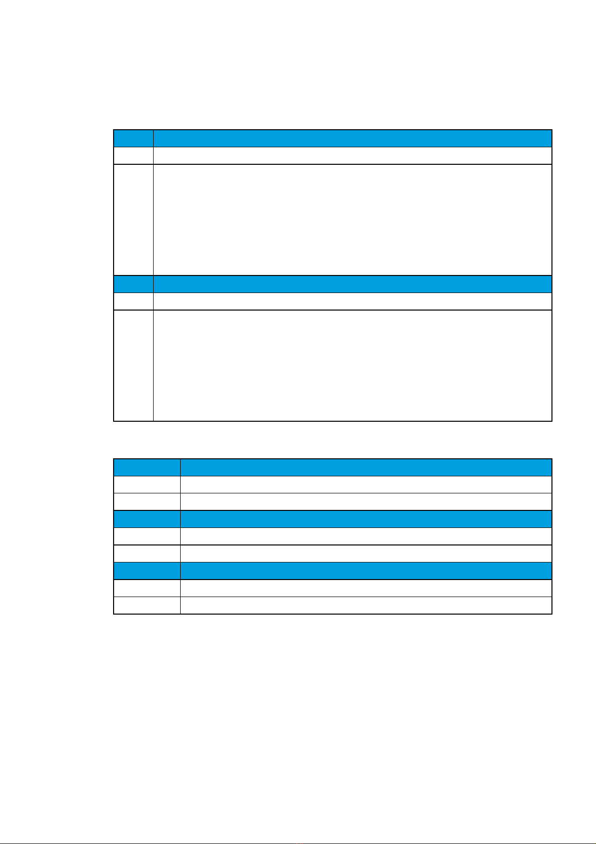
4.1. Panel structure . . . . . . . . . . . . . . . . . . . . . . . . . . . . . . . . . . . . . . . . . . . . . . . . . . . . . . . . . . .
4.1.1. Local panel structure . . . . . . . . . . . . . . . . . . . . . . . . . . . . . . . . . . . . . . . . . . . . . . . . .
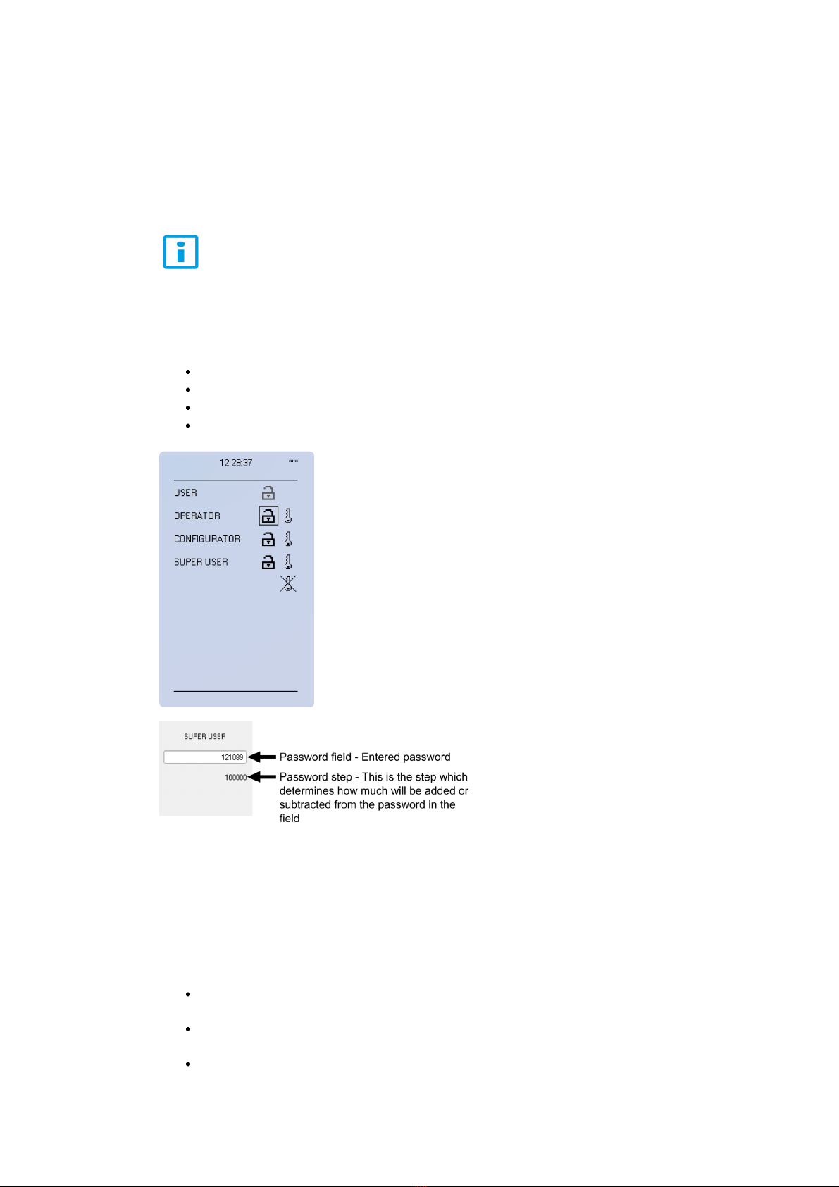
4.2. Conguring user levels and theirpasswords . . . . . . . . . . . . . . . . . . . . . . . . . . . . . . . . . . . .
5. Functions . . . . . . . . . . . . . . . . . . . . . . . . . . . . . . . . . . . . . . . . . . . . . . . . . . . . . . . . . . . . . . . . .
5.1. Functions included in AQ-E25x . . . . . . . . . . . . . . . . . . . . . . . . . . . . . . . . . . . . . . . . . . . . .
5.2. Measurements . . . . . . . . . . . . . . . . . . . . . . . . . . . . . . . . . . . . . . . . . . . . . . . . . . . . . . . . . .
5.2.1. Current measurement and scaling . . . . . . . . . . . . . . . . . . . . . . . . . . . . . . . . . . . . . .
5.2.2. Voltage measurement and scaling . . . . . . . . . . . . . . . . . . . . . . . . . . . . . . . . . . . . . .
5.2.3. Power and energy calculation . . . . . . . . . . . . . . . . . . . . . . . . . . . . . . . . . . . . . . . . .
5.2.4. Frequency tracking and scaling . . . . . . . . . . . . . . . . . . . . . . . . . . . . . . . . . . . . . . . .
5.3. Fault indicating functions . . . . . . . . . . . . . . . . . . . . . . . . . . . . . . . . . . . . . . . . . . . . . . . . . .
5.3.1. Non-directional overcurrent (I>;50) . . . . . . . . . . . . . . . . . . . . . . . . . . . . . . . . . . . . .
5.3.2. Non-directional earth fault (I0>; 50N) . . . . . . . . . . . . . . . . . . . . . . . . . . . . . . . . . . .
5.3.3. Directional overcurrent (Idir>; 67) . . . . . . . . . . . . . . . . . . . . . . . . . . . . . . . . . . . . . .
5.3.4. Directional earth fault (I0dir>; 67N) . . . . . . . . . . . . . . . . . . . . . . . . . . . . . . . . . . . . .
5.3.5. Intermittent earth fault (I0int>;67NT) . . . . . . . . . . . . . . . . . . . . . . . . . . . . . . . . . . .
5.3.6. Undervoltage (U<; 27) . . . . . . . . . . . . . . . . . . . . . . . . . . . . . . . . . . . . . . . . . . . . . . .
5.3.7. Neutral overvoltage (U0>; 59N) . . . . . . . . . . . . . . . . . . . . . . . . . . . . . . . . . . . . . . . .
5.3.8. Fault locator(21FL) . . . . . . . . . . . . . . . . . . . . . . . . . . . . . . . . . . . . . . . . . . . . . . . . .
5.4. General menu . . . . . . . . . . . . . . . . . . . . . . . . . . . . . . . . . . . . . . . . . . . . . . . . . . . . . . . . . .
5.5. Control functions . . . . . . . . . . . . . . . . . . . . . . . . . . . . . . . . . . . . . . . . . . . . . . . . . . . . . . . .
5.5.1. Setting group selection . . . . . . . . . . . . . . . . . . . . . . . . . . . . . . . . . . . . . . . . . . . . . .
5.5.2. Object control and monitoring . . . . . . . . . . . . . . . . . . . . . . . . . . . . . . . . . . . . . . . . .
5.5.3. Indicator object monitoring . . . . . . . . . . . . . . . . . . . . . . . . . . . . . . . . . . . . . . . . . . .
5.5.4. Milliampere outputs . . . . . . . . . . . . . . . . . . . . . . . . . . . . . . . . . . . . . . . . . . . . . . . . .
5.6. Monitoring functions . . . . . . . . . . . . . . . . . . . . . . . . . . . . . . . . . . . . . . . . . . . . . . . . . . . .
5.6.1. Disturbance recorder (DR) . . . . . . . . . . . . . . . . . . . . . . . . . . . . . . . . . . . . . . . . . .
5.6.2. Measurement recorder . . . . . . . . . . . . . . . . . . . . . . . . . . . . . . . . . . . . . . . . . . . . .
5.6.3. Total harmonic distortion (THD) . . . . . . . . . . . . . . . . . . . . . . . . . . . . . . . . . . . . . . .
5.6.4. Measurement value recorder . . . . . . . . . . . . . . . . . . . . . . . . . . . . . . . . . . . . . . . . .
6. System integration . . . . . . . . . . . . . . . . . . . . . . . . . . . . . . . . . . . . . . . . . . . . . . . . . . . . . . . . .
6.1. Communication protocols . . . . . . . . . . . . . . . . . . . . . . . . . . . . . . . . . . . . . . . . . . . . . . . .
6.1.1. NTP . . . . . . . . . . . . . . . . . . . . . . . . . . . . . . . . . . . . . . . . . . . . . . . . . . . . . . . . . . . .
6.1.2. Modbus/TCP and Modbus/RTU . . . . . . . . . . . . . . . . . . . . . . . . . . . . . . . . . . . . . . .
6.1.3. Modbus I/O . . . . . . . . . . . . . . . . . . . . . . . . . . . . . . . . . . . . . . . . . . . . . . . . . . . . . .
6.1.4. IEC 61850 . . . . . . . . . . . . . . . . . . . . . . . . . . . . . . . . . . . . . . . . . . . . . . . . . . . . . . .
6.1.5. GOOSE . . . . . . . . . . . . . . . . . . . . . . . . . . . . . . . . . . . . . . . . . . . . . . . . . . . . . . . . .
6.1.6. IEC 103 . . . . . . . . . . . . . . . . . . . . . . . . . . . . . . . . . . . . . . . . . . . . . . . . . . . . . . . . .
6.1.7. DNP3 . . . . . . . . . . . . . . . . . . . . . . . . . . . . . . . . . . . . . . . . . . . . . . . . . . . . . . . . . . .
6.1.8. IEC 101/104 . . . . . . . . . . . . . . . . . . . . . . . . . . . . . . . . . . . . . . . . . . . . . . . . . . . . .
6.1.9. SPA . . . . . . . . . . . . . . . . . . . . . . . . . . . . . . . . . . . . . . . . . . . . . . . . . . . . . . . . . . . .
6.2. Analog fault registers . . . . . . . . . . . . . . . . . . . . . . . . . . . . . . . . . . . . . . . . . . . . . . . . . . . .
6.3. Real time measurements to communication . . . . . . . . . . . . . . . . . . . . . . . . . . . . . . . . . .
7. Connections and application examples . . . . . . . . . . . . . . . . . . . . . . . . . . . . . . . . . . . . . . . . .
7.1. Connections of AQ-E25x . . . . . . . . . . . . . . . . . . . . . . . . . . . . . . . . . . . . . . . . . . . . . . . . .
7.2. Application example and its connections . . . . . . . . . . . . . . . . . . . . . . . . . . . . . . . . . . . . .
7.3. Two-phase, three-wire ARON input connection . . . . . . . . . . . . . . . . . . . . . . . . . . . . . . . .
7.4. Trip circuit supervision (95) . . . . . . . . . . . . . . . . . . . . . . . . . . . . . . . . . . . . . . . . . . . . . . .
8. Construction and installation . . . . . . . . . . . . . . . . . . . . . . . . . . . . . . . . . . . . . . . . . . . . . . . . .
8.1. Construction . . . . . . . . . . . . . . . . . . . . . . . . . . . . . . . . . . . . . . . . . . . . . . . . . . . . . . . . . .
AQ-E25x
Instruction manual
Version: 2.01
1 © Arcteq Relays Ltd

150
153
155
156
157
159
160
161
163
164
166
168
168
171
171
171
171
172
173
174
174
174
174
175
176
177
177
177
177
178
178
178
179
179
179
179
179
180
180
181
182
182
183
183
183
183
183
184
184
185
188
190
8.2. Construction . . . . . . . . . . . . . . . . . . . . . . . . . . . . . . . . . . . . . . . . . . . . . . . . . . . . . . . . . .
8.3. CPU module . . . . . . . . . . . . . . . . . . . . . . . . . . . . . . . . . . . . . . . . . . . . . . . . . . . . . . . . . .
8.4. Current measurement module . . . . . . . . . . . . . . . . . . . . . . . . . . . . . . . . . . . . . . . . . . . . .
8.5. Voltage measurement module . . . . . . . . . . . . . . . . . . . . . . . . . . . . . . . . . . . . . . . . . . . . .
8.6. Digital input module(optional) . . . . . . . . . . . . . . . . . . . . . . . . . . . . . . . . . . . . . . . . . . . . .
8.7. Digital output module (optional) . . . . . . . . . . . . . . . . . . . . . . . . . . . . . . . . . . . . . . . . . . . .
8.8. RTD & mA input module (optional) . . . . . . . . . . . . . . . . . . . . . . . . . . . . . . . . . . . . . . . . .
8.9. Serial RS-232 communication module (optional) . . . . . . . . . . . . . . . . . . . . . . . . . . . . . . .
8.10. LC 100 Mbps Ethernet communication module (optional) . . . . . . . . . . . . . . . . . . . . . . .
8.11. Double ST 100 Mbps Ethernet communication module (optional) . . . . . . . . . . . . . . . . .
8.12. Double RJ45 10/100 Mbps Ethernet communication module (optional) . . . . . . . . . . . .
8.13. Milliampere (mA) I/O module (optional) . . . . . . . . . . . . . . . . . . . . . . . . . . . . . . . . . . . . .
8.14. Dimensions and installation . . . . . . . . . . . . . . . . . . . . . . . . . . . . . . . . . . . . . . . . . . . . . .
9. Technical data . . . . . . . . . . . . . . . . . . . . . . . . . . . . . . . . . . . . . . . . . . . . . . . . . . . . . . . . . . . . .
9.1. Hardware . . . . . . . . . . . . . . . . . . . . . . . . . . . . . . . . . . . . . . . . . . . . . . . . . . . . . . . . . . . . .
9.1.1. Measurements . . . . . . . . . . . . . . . . . . . . . . . . . . . . . . . . . . . . . . . . . . . . . . . . . . . .
9.1.1.1. Current measurement . . . . . . . . . . . . . . . . . . . . . . . . . . . . . . . . . . . . . . .
9.1.1.2. Voltage measurement . . . . . . . . . . . . . . . . . . . . . . . . . . . . . . . . . . . . . . .
9.1.1.3. Power and energy measurement . . . . . . . . . . . . . . . . . . . . . . . . . . . . . . .
9.1.1.4. Frequency measurement . . . . . . . . . . . . . . . . . . . . . . . . . . . . . . . . . . . . .
9.1.2. CPU & Power supply . . . . . . . . . . . . . . . . . . . . . . . . . . . . . . . . . . . . . . . . . . . . . . .
9.1.2.1. Auxiliary voltage . . . . . . . . . . . . . . . . . . . . . . . . . . . . . . . . . . . . . . . . . . . .
9.1.2.2. CPU communication ports . . . . . . . . . . . . . . . . . . . . . . . . . . . . . . . . . . . .
9.1.2.3. CPU digital inputs . . . . . . . . . . . . . . . . . . . . . . . . . . . . . . . . . . . . . . . . . . .
9.1.2.4. CPU digital outputs . . . . . . . . . . . . . . . . . . . . . . . . . . . . . . . . . . . . . . . . .
9.1.3. Option cards . . . . . . . . . . . . . . . . . . . . . . . . . . . . . . . . . . . . . . . . . . . . . . . . . . . . .
9.1.3.1. Digital input module . . . . . . . . . . . . . . . . . . . . . . . . . . . . . . . . . . . . . . . . .
9.1.3.2. Digital output module . . . . . . . . . . . . . . . . . . . . . . . . . . . . . . . . . . . . . . . .
9.1.3.3. Milliampere module (mA out & mA in) . . . . . . . . . . . . . . . . . . . . . . . . . . .
9.1.3.4. RTD & mA input module . . . . . . . . . . . . . . . . . . . . . . . . . . . . . . . . . . . . . .
9.1.3.5. RS-232 & serial ber communication module . . . . . . . . . . . . . . . . . . . . .
9.1.3.6. Double LC 100 MbpsEthernet communication module . . . . . . . . . . . . . .
9.1.4. Display . . . . . . . . . . . . . . . . . . . . . . . . . . . . . . . . . . . . . . . . . . . . . . . . . . . . . . . . . .
9.2. Functions . . . . . . . . . . . . . . . . . . . . . . . . . . . . . . . . . . . . . . . . . . . . . . . . . . . . . . . . . . . . .
9.2.1. Energy monitoring functions . . . . . . . . . . . . . . . . . . . . . . . . . . . . . . . . . . . . . . . . .
9.2.1.1. Non-directional overcurrent (I>; 50) . . . . . . . . . . . . . . . . . . . . . . . . . . . . .
9.2.1.2. Non-directional earth fault (I0>; 50N) . . . . . . . . . . . . . . . . . . . . . . . . . . . .
9.2.1.3. Directional overcurrent (Idir>; 67) . . . . . . . . . . . . . . . . . . . . . . . . . . . . . .
9.2.1.4. Directional earth fault (I0dir>; 67N) . . . . . . . . . . . . . . . . . . . . . . . . . . . . .
9.2.1.5. Intermittent earth fault (I0int>; 67NT) . . . . . . . . . . . . . . . . . . . . . . . . . . . .
9.2.1.6. Undervoltage (U<; 27) . . . . . . . . . . . . . . . . . . . . . . . . . . . . . . . . . . . . . . .
9.2.1.7. Neutral overvoltage (U0>; 59N) . . . . . . . . . . . . . . . . . . . . . . . . . . . . . . . .
9.2.2. Control functions . . . . . . . . . . . . . . . . . . . . . . . . . . . . . . . . . . . . . . . . . . . . . . . . . .
9.2.2.1. Setting group selection . . . . . . . . . . . . . . . . . . . . . . . . . . . . . . . . . . . . . .
9.2.2.2. Object control and monitoring . . . . . . . . . . . . . . . . . . . . . . . . . . . . . . . . .
9.2.3. Monitoring functions . . . . . . . . . . . . . . . . . . . . . . . . . . . . . . . . . . . . . . . . . . . . . . .
9.2.3.1. Voltage transformer supervision (60) . . . . . . . . . . . . . . . . . . . . . . . . . . . .
9.2.3.2. Disturbance recorder . . . . . . . . . . . . . . . . . . . . . . . . . . . . . . . . . . . . . . . .
9.2.3.3. Total harmonic distortion (THD) . . . . . . . . . . . . . . . . . . . . . . . . . . . . . . . .
9.3. Tests and environmental . . . . . . . . . . . . . . . . . . . . . . . . . . . . . . . . . . . . . . . . . . . . . . . . .
10. Ordering information . . . . . . . . . . . . . . . . . . . . . . . . . . . . . . . . . . . . . . . . . . . . . . . . . . . . . . .
11. Contact and reference information . . . . . . . . . . . . . . . . . . . . . . . . . . . . . . . . . . . . . . . . . . . .
AQ-E25x
Instruction manual
Version: 2.01
© Arcteq Relays Ltd 2

Disclaimer
Please read these instructions carefully before using the equipment or taking any other actions with
respect to the equipment. Only trained and qualied persons are allowed to perform installation,
operation, service or maintenance of the equipment. Such qualied persons have the responsibility to
take all appropriate measures, including e.g. use of authentication, encryption, anti-virus programs,
safe switching programs etc. necessary to ensure a safe and secure environment and usability of the
equipment. The warranty granted to the equipment remains in force only provided that the instructions
contained in this document have been strictly complied with.
Nothing contained in this document shall increase the liability or extend the warranty obligations of the
manufacturer Arcteq Relays Ltd. The manufacturer expressly disclaims any and all liability for any
damages and/or losses caused due to a failure to comply with the instructions contained herein or
caused by persons who do not full the aforementioned requirements. Furthermore, the manufacturer
shall not be liable for possible errors in this document.
Please note that you must always comply with applicable local legislation and regulations. The
manufacturer gives no warranties that the content of this document is in all respects in line with local
laws and regulations and assumes no liability for such possible deviations.
You are advised to notify the manufacturer in case you become aware of any errors in this document or
of defects in the equipment.
The manufacturer reserves the right to update or amend this document at any time.
AQ-E25x
Instruction manual
Version: 2.01
3 © Arcteq Relays Ltd

Copyright
Copyright © Arcteq Relays Ltd. 2018. All rights reserved.
AQ-E25x
Instruction manual
Version: 2.01
© Arcteq Relays Ltd 4

1. Manual revision notes
1.1. Version 2 revision notes
Revision 2.00
Date 6.6.2019
Changes
- New more consistent look.
- Improved descriptions generally in many chapters.
- Improved readability of a lot of drawings and images.
- Updated protection functionsincludedin every IED manual.
- Every protection IED type now has connection drawing, application example drawingwith function block diagram
and application example with wiring.
- Added General-menu description.
Revision 2.01
Date 6.11.2019
Changes
- Added description for LED test and button test.
- Added display sleep timer description.
- Complete rewrite of every chapter.
- Improvements to many drawings and formula images.
- Order codes revised.
- Added double ST 100 Mbps Ethernet communication module and Double RJ45 10/100 Mbps Ethernet
communication module descriptions
1.2. Version 1 revision notes
Revision 1.00
Date 4.1.2018
Changes - The rst revision for AQ-E25x IED.
Revision 1.01
Date 14.8.2018
Changes - Added mA output option card description and ordercode
Revision 1.02
Date 18.1.2019
Changes - HMI display technical data added
AQ-E25x
Instruction manual
Version: 2.01
5 © Arcteq Relays Ltd

2. Abbreviations
CB – Circuit breaker
CBFP – Circuit breaker failure protection
CT – Current transformer
CPU – Central processing unit
EMC – Electromagnetic compatibility
HMI – Human machine interface
HW – Hardware
IED – Intelligent electronic device
IO – Input output
LED – Light emitting diode
LV – Low voltage
MV – Medium voltage
NC – Normally closed
NO – Normally open
RMS – Root mean square
SF – System failure
TMS – Time multiplier setting
TRMS – True root mean square
VAC – Voltage alternating current
VDC – Voltage direct current
SW – Software
uP - Microprocessor
AQ-E25x
Instruction manual
Version: 2.01
© Arcteq Relays Ltd 6

3. General
The AQ-E257 and AQ-E259energy management IEDs aremembers of the AQ-200 product line. The
hardware and software are modular:the hardware modules are assembled and congured according
to the application's I/O requirements and the software determines the available functions. This manual
describes the specic application of the AQ-E25xenergy management IED. For other AQ-200 series
products please consult therespective device manuals.
The AQ-25x IEDs are well-suited for centralized applications of transformer station monitoring. They
provide complete fault indication, monitoring, measuring and control for up to three (3) feeders. AQ-
E257 is designed to monitor up to two (2) feeders whereas AQ-E259 is desinged for up to three (3)
feeders. The AQ-E25x platform can control up to ten (10) objects, such as circuit breakers and
disconnecting switches. It can also communicate by using various communication protocols: IEC
61850, IEC 101/104, Modbus, DNP3 and SPA.
The centralized application eliminates the need to install separate RTUs or gateway devices in the
secondary distribution, thus making the complete solution cost-effective.
The AQ-E25x IEDs integrateinto a single equipment a fault location functionality and a kWh
measurement as accurate as that used by energy companies for billing. This combination of highly
accurate measurement technology and fault detection algorithms allowsthe AQ-E25xIEDs to be
applied for volt/varoptimization as well as fortracking power losses and reducingpower outages
through accurate fault location.
AQ-E25x
Instruction manual
Version: 2.01
7 © Arcteq Relays Ltd

4. IED user interface
4.1. Panel structure
The user interface section of an AQ-200 series device is divided into two user interface sections: one
for the hardware and the other for the software. You can access the software interface either through
the front panel or through the AQtivate freeware software suite.
4.1.1. Local panel structure
The front panel of AQ-250 series deviceshave multiple LEDs, control buttons and a local RJ-45
Ethernet port for conguration. Each unit is alsoequipped with an RS-485 serial interface and an RJ-45
Ethernet interfaceon the back of the device. See the image and list below.
Figure. 4.1.1. - 1. Local panel structure.
Four (4) freely congurableLEDs: "Power", "Error", "Start" and "Trip".
Sixteen (16) freely congurable LEDs with programmable legend texts.
Three (3) object control buttons: Choose the controllable object with the Ctrl button and the
control breaker with the I and the O buttons.
The L/R button switches between the local and the remote control modes.
Eight (8)buttons for IED local programming: the four navigation arrows, the Back and theOK
buttons, the Home and the password activation buttons).
Twelve (12) freely congurable function buttons (F1…F12).
One (1) RJ-45 Ethernet port for IED conguration.
The view in the screen is freely congurable with the buttons: you can change the setting groups or
control the relay's general logic. The status of the object (circuit breaker, disconnector) can be
displayed on the screen. All measured and calculated values regardless of the magnitude catecory
(current, voltage, power, energy, frequency, etc.) can be shown on the screen.
Holding the I(object control) button down for ve seconds brings up the button test menu. It displays
all the physical buttons on the front panel. Pressing any of the listed buttons marks them as tested.
When all buttons are marked as having been tested, you can press the Back buttonto close the button
test menu.
AQ-E25x
Instruction manual
Version: 2.01
© Arcteq Relays Ltd 8

4.2. Conguring user levels and theirpasswords
As a factory default, no user level is locked with a passwordin an IED. In order to activate the different
user levels, click the Lock button in the device's HMIand set the desired passwords for the different
user levels.
NOTE!
Passwords can only be set locally in an HMI.
A number of stars are displayed in the upper right corner of the HMI; these indicate the current user
level. The different user levels and their star indicators are as follows (also, see the image below for the
HMI view):
Super user (***)
Congurator (**)
Operator (*)
User( - )
You can set a new password for a user level by selecting the key icon next to the user level's name.
After this you can lock the user level by pressing the Return key while the lock is selected. If you need
to change the password, you can select the key icon again and give a new password. Please note that
in order to do this the user level whose password is being changed must be unlocked.
As mentioned above, the access level of the different user levels is indicated by the number of stars.
The required access level to change a parameter is indicated with a star (*) symbol if such is required.
As a general rule the access levels are divided as follows:
User:
Can view any menus and settings but cannot change any settings, nor operate breakers
or other equipment.
Operator:
Can view any menus and settings but cannot change any settings BUT can operate
breakers andother equipment.
Congurator:
Can change most settings such as basic protection pick-up levels or time delays,
breaker control functions, signal descriptions etc. and can operate breakers andother
equipment.
AQ-E25x
Instruction manual
Version: 2.01
9 © Arcteq Relays Ltd

Super user:
Canchange any setting and can operate breakers andother equipment.
NOTE!
Any user level with a password automatically locks itself after half an hour (30 minutes) of
inactivity.
AQ-E25x
Instruction manual
Version: 2.01
© Arcteq Relays Ltd 10

5. Functions
5.1. Functions included in AQ-E25x
This chapter presents the functions of the AQ-E257 and AQ-E259 energy management IEDs. The AQ-
E257 IED is able to monitor and control two feeders. The AQ-E259 IED is able to monitor and control
three feeders.
The AQ-E25x includes the following functions as well asthe numberof stages for those functions. The
mentioned fault indicating functions are accessible through the
Fault monitor
tab in the
Monitoring
menu.
Table. 5.1. - 1. Fault indicating functions of AQ-E25x.
Name(number of stages) IEC ANSI Description
NOC (1) I> 50 Non-directional overcurrent
NEF (1) I0> 50N Non-directional earth fault
DOC (1) Idir> 67 Directional overcurrent
DEF (1) I0dir> 67N Directional earth fault
UV (1) U< 27 Undervoltage
NOV (1) U0> 59N Neutral overvoltage
IEF (1) I0int> 67NT Intermittent earth fault
Table. 5.1. - 2. Control functions of AQ-E25x.
Name IEC ANSI Description
SGS - - Setting group selection
Table. 5.1. - 3. Monitoring functions of AQ-E25x.
Name IEC ANSI Description
CTS - - Current transformer supervision
VTS - 60 Voltage transformer supervision
DR - - Disturbance recorder
THD - - Total harmonic distortion
FLX - 21FL Fault locator
VREC - - Measurement value recorder
5.2. Measurements
5.2.1. Current measurement and scaling
The current measurement module (CT module, or CTM) is used for measuring the currents from
current transformers. The measured values are processed into the measurement database and they
are used by measurement and protection functions.It is essential to understand the concept of current
measurements to be able to get correct measurements.
AQ-E25x
Instruction manual
Version: 2.01
11 © Arcteq Relays Ltd

Figure. 5.2.1. - 2. Current measurement terminology
PRI:The primary current, i.e. the current which flows in the primary circuit and through the primary side
of the current transformer.
SEC:The secondary current, i.e. the current which the current transformer transforms according to its
ratios. This current is measured by the protection relay.
NOM:The nominal primary current of the protected object.
For the measurements to be correct the user needs to ensure thatthe measurement signals are
connected to the correct inputs, that the current direction is connected to thecorrect polarity, and that
the scaling is set according to the nominal values of the current transformer.
The relay calculates the scaling factors based on the set values of the CT primary, the CT secondary
and the nominal current. The relay measures the secondary current,the current output from the
current transformer installed into application's primary circuit. Therated primary and secondary
currents of the CT need to be set for the relay to "know" theprimary and per-unit values. With motors
and other specic electrical apparatus protections, the motor's nominal current should be set for the
values to be in per unit with regards to the apparatus nominal instead of the CT nominal. This is not
always mandatory as some relays still require manual calculations for the correct settings; however,
setting the relay's nominal current makes motor protection mucheasier and more straightforward. In
modern protection devices this scaling calculation is done internally after the current transformer's
primary current, secondary current and motor nominal currentare set.
AQ-E25x
Instruction manual
Version: 2.01
© Arcteq Relays Ltd 12

Normally, the primary current ratings for phase current transformers are 10 A, 12.5 A, 15 A, 20 A, 25
A, 30 A, 40 A, 50 A, 60 A and 75 A as well astheir decimal multiples, while the secondary current
ratings are 1 A and 5 A. Other, non-standard ratings can be directly connected asthe scaling settings
are flexible and have large ranges. For example, the ring core current transformer ratings may vary.
Ring core current transformers are commonly used for sensitive earth fault protection and their rated
secondary may be as low as 0.2 A in some cases.
The following chapter is an example on how to set the scaling of the current measurements forthe
selected current transformer and system load.
Example of CT scaling
The following gure presents howCTs are connected to the relay's measurement inputs. It also shows
example CT ratings andnominal current of the load.
Figure. 5.2.1. - 3. Connections.
The following table presents the initial data of the connection.
Table. 5.2.1. - 4. Initial data.
Phase current CT
- CT primary: 100 A
- CT secondary: 5 A
Ring core CT in Input I02
- I0CT primary: 10 A
- I0CT secondary: 1 A
Load (nominal)
36 A
- the phase currents are connected to the I01 residual via a Holmgren connection
- the starpoint of the phase current CT's secondary currentis towards the line
AQ-E25x
Instruction manual
Version: 2.01
13 © Arcteq Relays Ltd

Phase CT scaling
Next, to scale the current to per-unit values, we have to select whether the basis of the phase CT
scaling is the protected object's nominal current or the CT primary value.
If the CT values are chosen to be the basis for the per-unit scaling, the option "CT nom. p.u." is
selected for the "Scale meas to In" setting (see the image below).
Figure. 5.2.1. - 4. Setting the phase current transformer scalings to CT nominal.
Once the setting have been sent to the device, AQtivate calculates the scaling factors and displayes
them for the user. The "CT scaling factor P/S" describes the ratio between the primary current and the
secondary current. The per-unit scaling factors ("Ipu scaling") for both primary and secondary
valuesare also displayed (in this case they are the set primary and secondary currents of the CT).
If the protected object's nominal current ischosen to be the basis for the per-unit scaling, the option
"Object in p.u."is selected for the "Scale meas to In" setting (see the image below).
Figure. 5.2.1. - 5. Setting the phase current transformer scalings to the protected object's nominal current.
AQ-E25x
Instruction manual
Version: 2.01
© Arcteq Relays Ltd 14

Once the measurement scaling is tied to the protected object's nominal current, the user must set the
appropriateinput for the "Nominal current In" setting. One can now see the differences between
thetwo scaling options (CT nominal vs. object nominal). The "CT scaling factor P/S" is the direct ratio
between the set CT current values, and the "CT scaling factor NOM" is now the ratio between the set
CT primary and the nominal current. The "Ipu scaling primary" is now equal to the set nominal current,
and the "Ipu scaling secondary" is the ratio between the nominal current andthe "CT scaling factor
P/S".
Residual I0 CT scaling
Next, we set the residual IO CT scalings according to how the phase current CTs and the ring core CT
are connected to the module(see the Connections image at the beginning of this chapter).
The phase current CTs are connected to the module via a Holmgren (summing) connection, which
requires the use of coarse residual current measurement settings: the "I01 CT" settings are set
according to the phase current CTs' ratings (100/5 A).
Figure. 5.2.1. - 6. Residual I01 CT scaling (coarse).
The ring core CTisconnected to the CTM directly, which requires the use of sensitiveresidual current
measurement settings: the "I02CT" settings are set according to the ring core CT's ratings (10/2A).
Figure. 5.2.1. - 7. Residual I02CT scaling (sensitive).
Displaying the scaling
Depending on whether the scaling was done based on the CT primary values or the protected object's
nominal current, the measurements are displayed slightly differently. The rst of the two images shows
howthe measurements are displayed whenthe CT primary values are the basis for the scaling; the
second shows them whenthe protected object's nominal current is the basis for the scaling.
AQ-E25x
Instruction manual
Version: 2.01
15 © Arcteq Relays Ltd

Figure. 5.2.1. - 8. Scalings display (based on theCT nominal).
Figure. 5.2.1. - 9. Scalings display (based on the protected object's nominal current).
As the images above show, the scaling selection does not affect how primary and secondary currents
are displayed (as actual values). The only effect is that the per-unit system in the relay is scaled either
to the CT nominal or to the object nominal, making the settings input straightforward.
Example of zero sequence CT scaling
Zero sequence CT scaling (ZCT scaling) is done when a zero sequence CT instead of a ring core CT is
part of the measurement connection. In such a case the zero sequence CT should be connected to
the I02 channel which has lower CT scaling ranges (see the image below).
AQ-E25x
Instruction manual
Version: 2.01
© Arcteq Relays Ltd 16

Figure. 5.2.1. - 10. Connections of ZCT scaling.
The residual I0CT scaling is set according to the zero sequence CT's ratings, in this case 200/1.5 mA
(see the image below).
Based on these values, the earth fault protection setting (1× I0n) makes the function pick-up when the
primary current is at 200 mA (see the image below).
AQ-E25x
Instruction manual
Version: 2.01
17 © Arcteq Relays Ltd

Troubleshooting
When the measured current values differ from the expected current values, the following table offers
possible solutions for theproblems.
NOTE!
If you work with energized CTs, extreme caution needs to be taken when checking the
connections!An opened CT secondary circuit may generate dangerously high voltages. A
"buzzing" sound from the connector can indicate an open circuit.
Problem Solution
The measured current
amplitude in all phases
does not match the
injected current.
The scaling settings may be wrong, check that the settings match the expectations in AQtivate
(
Measurement
→
Transformers
→
Phase CT scaling
). Also check that the "Scale meas. to In" is set
accordingly. If possible, check the actual CTs and their ratings as there may have been a need to
change the original plan.
The measured current
amplitude does not
match one of the
measured phases./
Thecalculated I0 is
measured even though
it should not.
Check the wiring connections between the injection device or the CTs and the relay.
AQ-E25x
Instruction manual
Version: 2.01
© Arcteq Relays Ltd 18

The measured current
amplitudes are OK but
the angles are strange./
The phase unbalance
protection trips
immediately after
activation./
The earth fault
protection trips
immediately after
activation.
The phase currents are connected to the measurement modulebut the order or polarity of one or
all phases is incorrect. In AQtivate, go to
Measurement
→
Phasors
and check the "Phase current
vectors" diagram. When all connections are correct, the diagram (symmetric feeding) should look
like this:
See the following tables for the most common problems with phase polarity and network rotation
(mixed phases).
The following tablepresents the most common problems with phase polarity. Problems with phase
polarity are easy to nd because the vector diagram points towards the opposite polarity when a phase
has been incorrectly connected.
Table. 5.2.1. - 5. Common phase polarity problems.
The polarity of Phase L1 (A) is incorrect.
Phase currents
IL1: 1.00 ×In / 0.00 deg
IL2: 1.00 × In / 60.00 deg
IL3: 1.00 × In / 300.00 deg
Sequence currents
I1: 0.33 × In / 180.00 deg
I2: 0.67× In / 0.00 deg
I0Calc: 0.67 × In / 0.00 deg
Solution options:
- switch the wires between the connectors 1 and 2 in the CT module
- invert the polarity of IL1(
Measurement
→
Transformers
→
Phase CT scaling
)
The polarity of Phase L2(B) is incorrect.
Phase currents
IL1: 1.00 × In / 0.00 deg
IL2: 1.00 × In / 60.00 deg
IL3: 1.00 ×In / 120.00 deg
Sequence currents
I1: 0.33 × In / 0.00 deg
I2: 0.67 × In / -60.00 deg
I0Calc: 0.67 × In / 60.00 deg
Solution options:
-switch the wires between the connectors 3and 4in the CT module
-invert the polarity of IL2(
Measurement
→
Transformers
→
Phase CT scaling
)
AQ-E25x
Instruction manual
Version: 2.01
19 © Arcteq Relays Ltd
Table of contents
Other Arcteq Industrial Electrical manuals
Popular Industrial Electrical manuals by other brands

Murata
Murata GRM219R61C225KA88 Series Reference sheet

schmersal
schmersal TZF SPEZ operating instructions

Digital Equipment
Digital Equipment 3000 Upgrade information

HEIDENHAIN
HEIDENHAIN VT 121 operating instructions

Murata
Murata GRM033C80J683ME84 Series Reference sheet

Huawei
Huawei SUN2000-15KTL-50KTL-M3 Series user manual