Argo Malibu 257/6109 User manual

MADE IN
BRITAIN
Issue2 - 25/11/13 - Cat codes were incorrect.
Dimensions
Width - 110cm
Depth - 49.5cm
Height - 181cm
Malibu - 2 Drawer 3 Door Robe
Assembly Instructions - Please keep for future reference
If you need help or have damaged or missing parts, call the Customer Helpline: 08456 400800
Issue 4 - 03/09/14
Important - Please read these instructions fully before starting assembly
ALR3024
257/6109
249/4298
257/7861
268/8554
248/7803
238/5792
Issue 3 - 01/04/14 - New version with metal runners, 3 piece drawer wraps etc...
Issue 4 - 03/09/14 - Changed Drawer Back description to W682-124BCK.
Round Back Holders have been changed to Oblong Back Holders.

Safety and Care Advice
Important - Please read these instructions fully before starting assembly
• Warning: This unit weighs
approximately 76kgs.
Please lift with care.
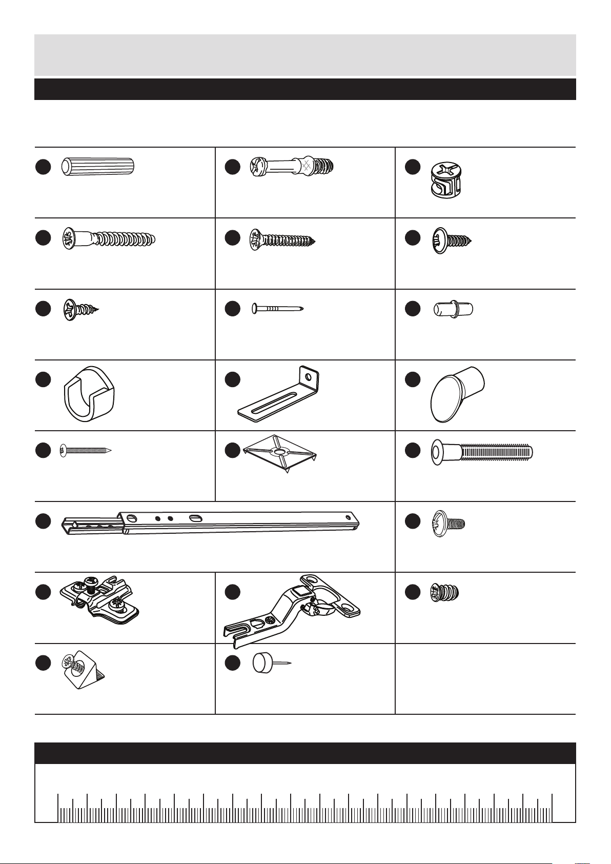
• Check you have all the
components and tools listed on
pages 1, 2 and 3.
• Remove all fittings from the
plastic bags and separate them
into their groups.
• Keep children and animals
away from the work area, small
parts could choke if swallowed.
• Parts of the assembly will be
easier with 2 people.
• Make sure you have enough
space to layout the parts before
starting.
• Do not stand or put weight on
the product, this could cause
damage.
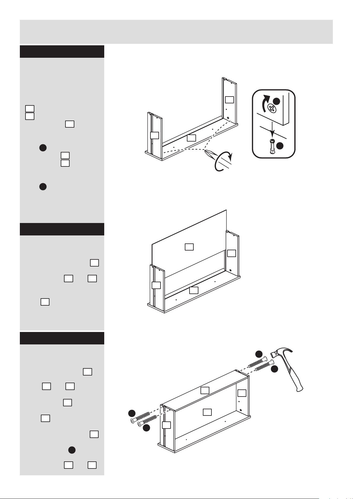
• Assemble the item as close to
its final position (in the same
room) as possible.
• Assemble on a soft level
surface to avoid damaging the
unit or your floor (use opened
out unit carton).
1
Care and maintenance
• Only clean using a damp cloth
and mild detergent, do no use
bleach or abrasive cleaners.
• From time to time check that
there are no loose screws on
this unit.
• This product should not be
discarded with household
waste. Take to your local
authority waste disposal centre.
• We do not
recommend the
use of power
drill/drivers for
inserting screws,
as this could damage the unit.
Only use hand screwdrivers.
• Safety note: It is
recommended that this unit is
secured to a wall using the
bracket supplied.
• Dispose of all packaging
carefully and responsibly.
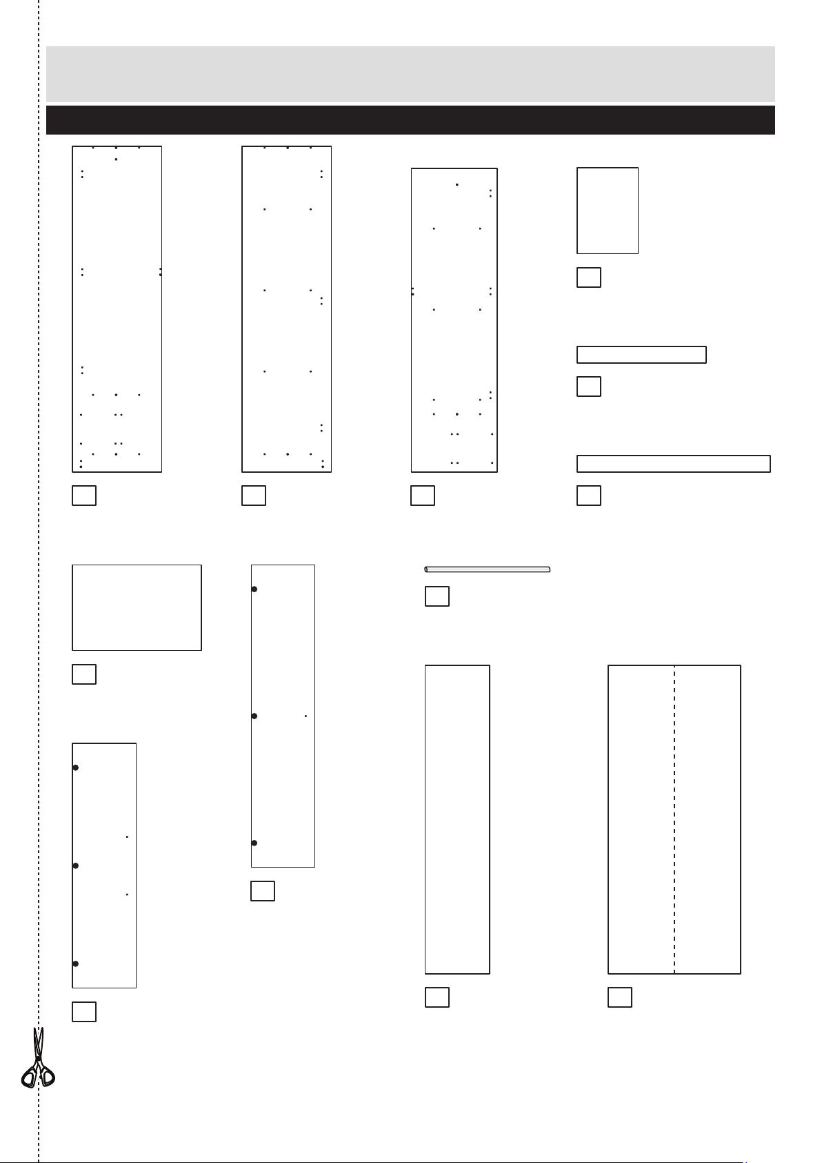
Components - Panels
Please check you have all the panels listed below
If you have damaged or missing components, call the
Customer Helpline: 08456 400800 quoting the reference
numbers below
1
6
7
80% x 2
90% x 1
80% x 1
Top (D2837A)
(1071 x 494mm)
Base (D2842A)
(1071 x 494mm)
Drawer Base (T693-367)
(693 x 367mm) x 2
Drawer Back (W682-124BCK)
(682 x 124mm) x 2
Left Drawer Side (W370-124LH)
(370 x 124mm) x 2
Right Drawer Side (W370-124RH)
(370 x 124mm) x 2
2
3
4
5
Drawer Front (D2783A)
(710 x 156mm) x 2

Components - Panels
Please check you have all the panels listed below
2
89
80% x 2
90% x 1
80% x 1
If you have damaged or missing components, call the
Customer Helpline: 08456 400800 quoting the reference
numbers below
Small Back (X1710-358)
(1710 x 358mm)
Large Back (X1710-734)
(1710 x 734mm)
10
11
12
13
14
15
16
18 19
Hanging Rail (FHR708)
(708mm long)
17
Left Side (D2838A)
(1808 x 496mm)
Shelf (D2843A)
(339 x 476mm) x 3
Right Side (D2839A)
(1808 x 496mm)
Plinth (D2844A)
(1071 x 92mm)
Back Rail (D2847A)
(716 x 92mm)
Upright (D2840A)
(1684.5 x 477mm)
Horizontal (D2841A)
(716 x 476mm)
Large Door (D2845A)
(1678 x 353mm)
Small Door (D2846A)
(1358 x 353mm) x 2

Please check you have all the fittings listed below
3
Components - Fittings If you have damaged or missing components, call the
Customer Helpline: 08456 400800 quoting the reference
numbers below
Note: The quantities below are the correct amount to complete the assembly. In some cases
more fittings may be supplied than are required.
Ruler - Use this ruler to help correctly identify the screws
mm 10 20 30 40 50 60 70 80 90 100 110 120 130 140 150 160 170
A
Wooden dowel (F22) x 12
B
Metal dowel (F901) x 4
C
D E
G H I
Small locking
nut (F3) x 4
40mm Screw (F910) x 20
J K
Nail (F51) x 37
25mm Screw (F50) x 7
F
13mm Screw (F79) x 1
13mm Screw (F63) x 20
Rail holder
(F1014) x 2 Bracket (F327 x 1)
S
P
Hinge (F522) x 9
L
Hinge plate (F523) x 9
Handle (F631) x 7
R
M
Nail screw (F277) x 5
Shelf stud (F110) x 12
O
Q
T
U V
Knock-in Peg (F171GY) x 8
Plastic Nail (F91) x 5
9mm Screw (F74) x 4
9mm Screw (F73) x 8
Wedgefix (F639) x 8
Drawer runner (F1004) x 4
N
Back holder (F276) x 5
*These can also be round

Assembly Instructions
4
If you have damaged or missing components, call the
Customer Helpline: 08456 400800 quoting the reference
numbers below
Step 1
Tools required
Rule
Scissors
Spirit
level
Hammer Bradawl
Eye protection
(when using a
hammer or drill)
Cross-head
screwdriver
Step
ladder
Electric drill
(only use
when drilling
into walls)
Square
mm 10 20 30 40 50 60 70 80 90 100
80% x 2
x 2
BB
B
1
x 2 x 2
C
Note: Due to the manufacturing process, the holes for the
locking nut can be on either surface of the drawer sides.
CC
23
Step 2
Prepare the 2 drawer
fronts
Screw 2 metal dowels
into each of the drawer
fronts .
Note: Tighten the metal
dowels up fully against
the panels.
B
1
Prepare the drawer
sides
Insert a small locking
nut into the hole
shown on the left drawer
side and the right
drawer side .
Note: The arrow on the
locking nut must point
towards the hole in the
edge of the panel.
C
2
3

O
O
1
1
Assembly Instructions
5
Step 3
Step 4
x 2
B
B
C
Note: The locking nuts can be on either surface of the drawer sides.
Make sure that the small groove is on the inside, as shown.
Step 3
Attach the drawer
sides to the drawer
fronts
Push the left drawer sides
. and right drawer sides
. onto the back of the
drawer fronts .
Turn the small locking
nuts on the left
drawer side and right
drawer side .
Note: Turn the locking
nuts clockwise to
secure panels - more
than 1/2 a turn.
2
3
1
C
C
2
3
Fit the drawer base
Slide the drawer base
down the grooves in the
drawer sides and
and down into the
groove in the drawer
front .
Step 5
Fit the drawer back
Fit the drawer back
between the drawer
sides and .
Make sure that the
drawer base fits into
the groove in the drawer
back .
Hold the drawer back
in position and tap the
knock-in pegs
through the holes in the
drawer sides and .
5
2 3
1
4
2 3
5
4
4
O
2 3
x 2
x 2
O
O
2
3
5
2
3
2
3
5
4
80% x 2

Assembly Instructions
6
Step 6
80% x 2
90% x 1
80% x 1
10mm
A
A
A
Prepare the horizontal
Tap 2 wooden dowels
into the horizontal .
Note: Wooden dowels
must not stick out from
the edge by more than
10mm or they may
damage other panels.
A
14
Finished
front edge
plain
chipboard
surface
14
Attach the handles
Attach 2 handles to
each of the drawer fronts
. using screws .
Note: Do not
overtighten the screw.
L
E
1
Step 7
Fit the wedgefixes
Turn the drawer
assemblies over and
slide 4 wedgefixes
into the front and back
grooves, as shown, and
tighten up the screws.
Step 8
U
x 2
x 2
U
U
U
U
U
L
E
L
E
80% x 2 1

D
D
Finished
front edge
Assembly Instructions
7
Step 9
Prepare the upright
a: Push a rail holder
into the upright .
Make sure that it is fitted
straight, in line with the
panel edges and then
secure with screw .
Place 2 runners on
the upright as shown.
Slide back the top of
runner and use the 2nd
hole from the front to fit
the 1st screw .
b: Slide the runner
back the other way and
fit the 2nd screw into
the corresponding hole
in the upright .
Tap 2 wooden dowels
into the left upright .
Note: Wooden dowels
must not stick out from
the edge by more than
10mm or they may
damage other panels.
Fit 3 hinge plates onto
the upright making
sure that the slot is
facing towards the
finished front edge.
10
T
T
R
10
10
P
P
A
a:
b:
T
PT
P
T
T
J
G
Finished
front edge
Finished
front edge
A
A
R
R
R
Finished
front edge
T
P
10mm
A
R
J
10
G
10
10
10
Finished
front edge
14
plain
chipboard
surface
10
Step 10
Fit the horizontal to
the upright
Push the horizontal
onto the upright and
secure it with 2 screws .
14
10
D

Finished
front edge
D
D
6
Assembly Instructions
8
Step 11
80% x 2
90% x 1
80% x 1
A
Prepare the top and
base
Tap 2 wooden dowels
into the top and the
base .
A
6
7
A
Finished
front edge
6
A
A
Finished
front edge
7
plain chipboard surface
Finished
front edge
D
7
plain chipboard surface
D
Step 12
Fit the top and base
to the upright
One at a time, push the
top and base
onto the upright and
secure each one with
2 screws .
6 7
10
D
10

D
D
D
D
R
R
R
Assembly Instructions
9
Step 13
Step 14
Fit the right side
Push the right side
onto the assembly
and secure it with 4
screws .
Step 15
Prepare the right side
Fit 3 hinge plates onto
the right side , making
sure that the slot is
facing towards the
finished front edge.
R
R
99
Finished
front edge
9
D
Prepare the back rail
and plinth
Tap 2 wooden dowels
into the back rail and
the plinth .
A
12
13
A
A
A
A
Plain
chipboard
surface
Plain
chipboard
surface
12
13
9

Finished
front edge
Finished
front edge
Assembly Instructions
10
Step 16
80% x 2
90% x 1
80% x 1
Step 17
Fit the plinth and the
back rail
a: Push the plinth
onto the right side
and secure it with a
screw .
b: Push the back rail
onto the upright and
secure it with a screw .
13
D
9
12
10
D
T
P
T
P
Finished
front edge
T
P
T
T
R
R
R
J
G
Prepare the left side
a: Place 2 runners on
the left side as
shown. Slide back the
top of runner and use the
2nd hole from the front
to fit the 1st screw .
b: Slide the runner
back the other way and
fit the 2nd screw into
the corresponding hole
in the left side .
Fit 3 hinge plates onto
the right side making
sure that the slot is
facing towards the
finished front edge.
Push a rail holder into
the left side . Make
sure that it is fitted
straight, in line with the
panel edges and then
secure with screw .
8
T
T
8
P
P
8
8
R
8
J
G
8
D
D
13
12
a:
b:
Note: Support the
back rail until the left
side has been fitted
in the next step.
9
10

Finished
front edge
Assembly Instructions
11
Step 18
Step 19
Fit the left side
Push the left side
onto the assembly
and secure it with 8
screws .
8
D
The measurement from top corner X to bottom corner X must be
equal to the measurement from top corner Y to bottom corner Y
a:
Fit the back panels
a: Square up the unit by
making sure that
measurement x:x equals
y:y.
Place the small back
and the large back
down onto the unit as
shown.
Make sure that the
backs are pushed
up tight against
each other and that
they meet over the
back edge of the
upright.
b: Nail around the
outside edges of the
backs.
Note: Do not nail where
the backs meet. Nails
should be spaced about
150mm apart.
18
19
H
D
D
D
D
D
D
D
D
8
y
x
y
yy
x
b:
H
Note: Do not
nail where the
backs meet.
18
19

12
Ix 4
Ix 4
Ix 4
11
11
11
Step 21
Secure the backs and
fit the 4 plastinails
Tap the nail screws
through the back holders
. and down between
the backs and
into the back edge
of the divider.
Keep tapping the
nail screws in
until the back
holders dig
into the small and
large back.
Tap 2 plastic
nails into the
bottom edge of
each side and
. as shown.
Tap 1 plastic nail into
the plinth as shown.
Carefully stand the
unit up for the next
step.
M
N
18 19
M
N
Warning: The
unit is heavy.
Lift with care.
Fit the hanging rail
and the shelves
Push the hanging rail
into the rail holders .
For each of the 3 shelves
. , insert 4 shelf studs
. .
Lower the 3 shelves
down onto the shelf
studs .
17
J
18
19
NM +
Assembly Instructions
Step 20
V
VV
V
V
8
9
8
9
17
J
17
I
11
I
11
V
V
13
13
Note: These can
also be round
M
N
N

Assembly Instructions
13
Step 22
Fit the drawers
Starting with the bottom
drawer, slide both the
runners forward and
locate the drawer sides
. and between
them, lining up the holes
in the drawer wrap with
the 2nd 'threaded' holes
in the runners .
Working from the inside
of the drawer, insert 2
screws through the
drawer sides and out into
the 2nd threaded hole in
the runner.
Note: Do not overtighten
the screws.
If they catch on the
runner you may need to
loosen them slightly.
Step 23
Prepare the 3 doors
Push fit 3 hinges into
each of the 2 small doors
. and the large door .
Secure each hinge with
2 screws .
Note: Before securing
with the screws, make
sure that the hinges are
positioned at 90 degrees
with the edge of the
door.
G
S
1615
S
G
G
90
S
x 2
S
G
G
S
G
G
S
G
G
S
G
G
S
G
G
15
16
2nd threaded
hole
P
Q
Q
Q
P
2 3
P
Q

Small piece of
waste wood
Small piece of
waste wood
Insert drawer
Lift front of drawer whilst
inserting to overcome
the ‘stop’ system.
Note: To ensure that
your drawer runs
smoothly, spray a small
amount of furniture
polish into the grooves.
14
ONLY drill this hole
in 1 small door
Drill a handle hole in
each small door
Important: Please follow
these instructions
carefully.
Lay the 2 small doors
down onto a smooth
surface.
Check that the hinges
and holes are in the
same place as the
diagrams.
Note: We recommend
the use of a small piece
of waste wood, placed
behind the hole while
drilling, to reduce the
possibility of any
breakout.
Using the pilot hole in
the rear face of the door,
drill through the hole
indicated opposite, using
a 2.5mm diameter drill.
Turn the door over and
open out the 2.5mm hole
that you have just drilled
by drilling back through it
with a 5mm drill.
IMPORTANT
Carefully choose which hole you need
to drill in each of the 2 small doors
15
ONLY drill this hole
in 1 small door
This will be the
left small door
This will be the
right small door
15
15
Assembly Instructions
Step 24

Assembly Instructions
15
Step 25
Fit doors and handles
Note: The easiest way to
attach each door and
. is to fit the top hinge
first, then align and fit the
other hinges.
a: Push the hinge
onto the front part of the
hinge plate .
The recess at the bottom
of screw B goes into the
slot in the hinge plate.
b: Keep the hinge
FLAT against the hinge
plate as you slide it
across as far as it will go.
Tighten screw A.
c: The hinge must be
flat against the hinge
plate prior to any
adjustment.
d: The hinge must
NOT be AT AN ANGLE
to the hinge plate
when assembled.
This would indicate that
the recess at the bottom
of screw B had not
located in the slot in the
hinge plate and the hinge
would not be secure.
Remove the hinge from
the hinge plate and then
re-assemble being
careful to follow
instructions a-c.
e: Attach a handle to
each door and
using screws .
S
S
S
R
R
R
S
R
L
E
15
16
15 16
a: b:
c: d:
R
S
R
R
B
R
S
S
S
A
S
R
B
e:
Note: When fitting the small doors,
make sure that the handle hole
you had to drill is nearest to the
bottom of the door.
15
16
15
L
E
L
L

Insert drawer
Lift front of drawer whilst
inserting to overcome
the ‘stop’ system.
Note: To ensure that
your drawer runs
smoothly, spray a small
amount of furniture
polish into the grooves.
16
Assembly Instructions
Step 26
b:
c:
d:
a:
Adjust the doors if
needed
a: Before adjusting the
doors, use a spirit level
to check the base (or
top) of the unit is level,
front-to-back and
side-to-side in the 3
positions shown.
Use suitable packing
pieces (not supplied) to
make the unit level
BEFORE making any
adjustment to the hinges,
as shown.
b: Height adjustment.
Loosen screws A on
hinge plates and move
door up or down as
required.
Retighten screw A.
c: Forward and Back
adjustment.
Loosen screw B on hinge
plate and move door in
or out as required.
Retighten screw B.
d: Sideways
adjustment.
To move door ‘out’
loosen screw C.
To move door ‘in’ tighten
screw C.
A
A
B
C

Assembly Instructions
If you need help or have damaged or missing parts, call the Customer Helpline: 08456 400800
and quote the reference numbers on the component pages.
Argos Ltd, 489-499 Avebury Boulevard, Central Milton Keynes, MK9 2NW
17
Step 27
Attach bracket to top
To prevent possible
overbalancing, we
recommend that this unit
is secured to a suitable
wall by use of the
bracket fitted to the
top of the unit.
Fixings are not supplied,
as they will need to suit
the wall type and the
length of screw will
depend on the distance
from the back of the unit
to the wall.
Fix the bracket
loosely onto the top of
the unit using screw
and mark the wall for the
wall fixing.
Swivel the bracket
away from the wall and
drill a hole in the wall
using a suitable drill bit
and fit your wall fixing.
Swivel the bracket
back and fix the bracket
to the wall, then tighten
screw .
Note: Take care when
drilling the wall that you
do not drill into any
pipes, wires etc.
If in doubt, consult an
expert.
Assembly is complete
Warning: The
unit is heavy.
Lift with care.
K
K
F
K
K
F
Top of Unit
WALL
WALL
Back of Unit
K
K
F
F


ALR3024
This manual suits for next models
4
Table of contents
Popular Indoor Furnishing manuals by other brands

Comfortex
Comfortex Somfy INSTALLATION & CARE INSTRUCTIONS

Quoizel
Quoizel QR1419PN Assembly instruction sheet

INOSIGN
INOSIGN Paris TOKYO 08 Assembly instruction

Amish Country Poly
Amish Country Poly CLASSIC 2FT GLIDER AC30 Assembly instructions

Next
Next 233434 Assembly instructions

NobleChairs
NobleChairs Epic manual

OSP Home Furnishings
OSP Home Furnishings SIERRA SRA07 manual

World Market
World Market RYDER 574837 Assembly instructions

Tennsco
Tennsco 1472 Assembly Instructions/Parts Manual

Argos
Argos 392/4839 Assembly instructions

Schulz Speyer
Schulz Speyer Softline Assembly guide

Ballard Designs
Ballard Designs Large Eastman Secretary MO386 Assembly instructions