Ariens Pro-24 Brush Cutter User manual

Owner/Operator Manual
Manuel du Propriétaire/Utilisateur
Model
911707 – Pro-24 HW Brush Cutter – CARB
Brush Cutter
04453400 1/12
Printed in USA
ENGLISH
FRENCH
Gasoline containing up to 10% ethanol (E10) or up to 10% MTBE (methyl tertiary butyl ether) is
acceptable for use in this machine.
The use of any gasoline exceeding 10% ethanol (E10) or 10% MTBE will void the product
warranty.
Il est possible d’utiliser de l’essence contenant jusqu’à 10% d’éthanol (E10) ou 10% de MTBE
(éther méthyl-tertiobutylique) sur cette machine.
L’utilisation d’une essence contenant plus de 10% d’éthanol (E10) ou de 10% de MTBE
annulent la garantie.

GB - 2
Safety . . . . . . . . . . . . . . . . . . . . . . . . . . . 4
Assembly . . . . . . . . . . . . . . . . . . . . . . . . 8
Controls and Features. . . . . . . . . . . . . 11
Operation . . . . . . . . . . . . . . . . . . . . . . . 12
Maintenance. . . . . . . . . . . . . . . . . . . . . 14
Service and Adjustments . . . . . . . . . . 17
Storage . . . . . . . . . . . . . . . . . . . . . . . . . 26
Troubleshooting. . . . . . . . . . . . . . . . . . 27
Service Parts . . . . . . . . . . . . . . . . . . . . 28
Specifications . . . . . . . . . . . . . . . . . . . 29
Warranty . . . . . . . . . . . . . . . . . . . . . . . . 30
NON-ENGLISH MANUALS
Manuals in languages other than
English may be obtained from
your Dealer. Visit your dealer or
www.ariens.com for a list of
languages available for your
equipment.
Manuals printed in languages
other than English are also
available as a free download on
our website:
http://www.ariens.com
MANUALES EN IDIOMAS
DIFERENTES DEL INGLES
Puede obtener manuales en
idiomas diferentes del inglés en
su distribuidor. Visite a su
distribuidor o vaya a
www.ariens.com paraobtener una
lista de idiomas disponibles para
su equipo.
También puede imprimir
manuales en idiomas diferentes
del inglés descargándolos
gratuitamente de nuestra página
Web:
http://www.ariens.com
MANUELS NON ANGLAIS
Des manuels dans différentes
langues sont disponibles chez
votre revendeur. Rendez-vous
chez votre revendeur ou allez sur
le site www.ariens.com pour
consulter la liste des langues
disponibles pour votre
équipement.
Les manuels imprimés dans des
langues différentes de l’anglais
sont également disponibles en
téléchargement gratuit sur notre
site Web :
http://www.ariens.com
THE MANUAL
Before using the unit, carefully and
completely read your manuals. The contents
will give you an understanding of safety
instructions and controls during normal
operation and maintenance.
All reference to left, right, front, or rear are
given from the operator’s position, facing the
direction of forward travel.
ENGINE MANUAL
The engine on this unit is covered by a
separate manual specific to the engine. This
manual is included in the literature package
that shipped with the unit. Refer to this
manual for engine service recommendations.
If the engine manual is not available, contact
the engine manufacturer for a replacement
manual.
SERVICE AND REPLACEMENT
PARTS
When ordering replacement parts or making
service inquiries, know the Model and Serial
numbers of your unit and engine.
Numbers are located on the product
registration form in the unit literature
package. They are also printed on a serial
number label, located on the frame of your
unit. See Figure 1.
• Record Unit Model and Serial numbers
here:
• Record Engine Model & Serial numbers
here:
TABLE OF CONTENTS
INTRODUCTION
© Copyright 2012 Ariens Company

GB - 3
PRODUCT REGISTRATION
The Ariens dealer must register the product
at the time of purchase. Registering the
product will help the company process
warranty claims or contact you with the latest
service information. All claims meeting
requirements during the limited warranty
period will be honored, whether or not the
product registration card is returned. Keep a
proof of purchase if you do not register your
unit.
Customer Note: If the Dealer does not
register your product, please fill out, sign and
return the product registration card to Ariens
or go to www.ariens.com on the internet.
UNAUTHORIZED REPLACEMENT
PARTS
Use only Ariens replacement parts.
Replacing any part on this vehicle with
anything other than an Ariens authorized
replacement part may adversely affect the
performance, durability, or safety of this unit
and may void the warranty. Ariens disclaims
liability for any claims or damages, whether
warranty, property damage, personal injury or
death arising out of the use of unauthorized
replacement parts. To locate your nearest
Ariens Dealer, go to www.ariens.com on the
Internet.
DEALER DELIVERY
CAUTION: DO NOT drop machine when
loading or unloading or damage to rear axle
may occur. Dealer should advise customer of
the same.
Dealer should:
1. Check that all assembly and
adjustments have been properly
completed.
2. Fill out Original Purchaser Registration
Card and return the card to Ariens.
3. Explain Ariens Limited Warranty Policy.
4. Explain recommended lubrication and
maintenance. Advise customer on
adjustments.
5. Instruct customer on controls and
operation of unit. Discuss and
emphasize the Safety Rules. Give
customer Owner/Operator, Parts, and
Engine manuals. Advise customer to
thoroughly read and understand them.
DISCLAIMER
Ariens reserves the right to discontinue,
make changes to, and add improvements
upon its products at any time without public
notice or obligation.The descriptions and
specifications contained in this manual were
in effect at printing. Equipment described
within this manual may be optional. Some
illustrations may not apply to your unit.
Figure 1
Unit Serial Number Label
Engine Serial Number Label

GB - 4
SAFETY ALERTS
Look for these symbols to point
out important safety precautions.
They mean:
Attention!
Personal Safety Is Involved!
Become Alert!
Obey The Message!
The safety alert symbols above and signal
words below are used on decals and in this
manual.
Read and understand all safety messages.
NOTATIONS
NOTE: General reference information for
proper operation and maintenance practices.
IMPORTANT: Specific procedures or
information required to prevent damage to
unit or attachment.
PRACTICES AND LAWS
Practice usual and customary safe working
precautions, for the benefit of yourself and
others. Understand and follow all safety
messages. Be alert to unsafe conditions and
the possibility of minor, moderate, or serious
injury or death. Learn applicable rules and
laws in your area.
REQUIRED OPERATOR
TRAINING
Original purchaser of this unit was instructed
by the seller on safe and proper operation. If
anyone other than the original purchaser will
use the unit, ALWAYS provide this manual
and any needed safety training before
operation.
SAFETY
WARNING: This cutting machine
is capable of amputating hands
and feet and throwing objects.
Failure to observe the safety
instructions in the manuals and
on decals could result in serious
injury or death.
Slopes are a major factor related
to slip and fall accidents.
Operation on all slopes requires
extra caution. Maximum slope
angle of operation is 25º.
Tragic accidents can occur if the
operator is not alert to the
presence of children. Never
assume that children will remain
where you last saw them.
Gasoline is extremely flammable
and the vapors are explosive,
handle with care.
Stop unit and engine and allow
moving parts to stop before
leaving operator’s position.
DANGER: IMMINENTLY
HAZARDOUS SITUATION! If not
avoided, WILL RESULT in death or
serious injury.
WARNING: POTENTIALLY
HAZARDOUS SITUATION! If not
avoided, COULD RESULT in
death or serious injury.
CAUTION: POTENTIALLY
HAZARDOUS SITUATION! If not
avoided, MAY RESULT in minor or
moderate injury. It may also be
used to alert against unsafe
practices.

GB - 5
SAFETY DECALS AND
LOCATIONS
ALWAYS replace missing or damaged safety
decals. Refer to for safety decal locations.
1. DANGER!
TO AVOID SERIOUS INJURY OR DEATH
2. DANGER!
KEEP HANDS AND FEET AWAY
SAFETY RULES
If unit is to be used by someone other than
original purchaser; loaned, rented or sold,
ALWAYS provide this manual and any
needed safety training before operation.
Learn applicable rules and laws in your area,
including those that may restrict the age of
the operator.
Read, understand and follow all safety
practices in Owner/Operator Manual before
beginning assembly. Failure to follow
instructions could result in personal injury
and/or damage to unit.
If the operator or the mechanic cannot read
the manual, it is the owner’s responsibility to
explain it to them. Only the user can prevent
and is responsible for accidents or injuries
occurring to themselves, other people or
property.
Do not allow operation of machine by
untrained personnel.
ALWAYS remove key (if equipped) and
disconnect wire from spark plug before
assembly. Unintentional engine start up can
cause death or serious injury.
Complete a walk around inspection of unit
and work area to understand:
• work area
• your unit
• all safety decals.
Clear work area of stones, sticks, wire and
foreign objects which might be picked up and
thrown. Tall grass can hide obstacles.
Know the work area. Stay alert for holes,
rocks, rough terrain and hidden hazards.
Keep away from drop-offs, ditches, or
embankments that could cause operator to
lose footing or control of unit.
ALWAYS be aware of traffic when operating
along streets or curbs.
Keep work area clear of all persons, children
and pets.
Keep children out of the work area and under
the watchful care of a responsible adult.
ALWAYS operate unit when there is good
visibility and light.
Read the operator’s manual.
Do not allow operation of
machine by untrained personnel.
Keep children and others away
from unit while operating.
Never direct discharge toward
other people. Thrown objects can
cause injury.
Do not operate mower unless
guards are in operating position
or entire bagger is attached.
Keep safety devices (guards,
shields, switches, etc.) in place
and working.
07700020
Figure 2 2
1
OL1801
OL4370
OL0910
OL3030
Shut off engine, remove key, and
read manual before you adjust or
repair unit.

GB - 6
DO NOT mow wet grass.
ALWAYS be sure of your footing. Keep a firm
hold on handlebar. Walk, NEVER run.
Engine/blade control feature on mower stops
engine and blade within 3 seconds whenever
operator releases handlebar control. Check
this feature frequently. If feature fails to
operate, disconnect spark plug wire and
adjust or have it repaired before using unit.
Only trained adults may operate or service
unit. Training includes actual operation. The
owner is responsible for training users.
NEVER operate after or during the use of
medication, drugs or alcohol. Unit requires
complete and unimpaired attention.
NEVER allow children to use or service
mower.
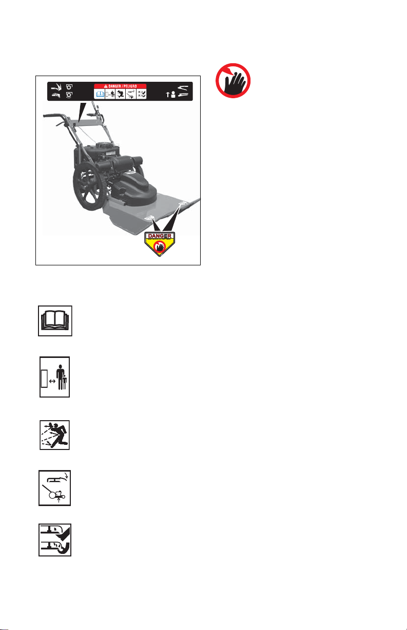
ALWAYS keep hands and feet away from
rotating parts. Rotating parts can cut off body
parts.
ALWAYS keep hands away from pinch points.
Fumes from engine exhaust can cause death
or serious injury. DO NOT run engine in an
enclosed area.
ALWAYS protect eyes, face, and body with
adequate safety gear and protective clothes.
Wear sturdy footwear, gloves, a hard hat and
safety goggles or safety glasses with side
shields while operating mower.
Wear appropriate hearing protection.
NEVER operate mower barefoot or when
wearing open sandals or canvas shoes.
NEVER wear loose clothes, long hair or
jewelry that may get caught in rotating parts.
ALWAYS stand clear of discharge when
operating unit.
NEVER direct discharge toward bystanders.
Operator is responsible for bystander safety.
DO NOT touch hot parts. Allow parts to cool.
Keep safety devices or guards in place and
functioning properly. NEVER modify or
remove safety devices.
Read, understand, and follow all instructions
in the manual and on the machine before
starting. Understand:
• How to operate all controls
• The functions of all controls
• How to STOP in an emergency.
DO NOT attempt to start your engine until
you know what the controls do and how they
work.
DO NOT tilt mower when starting it.
Keep feet away when starting engine.
Never leave a running unit unattended.
Take all possible precautions when leaving
unit unattended.
ALWAYS shut off engine and disconnect
spark plug wire to prevent accidental starting
or unauthorized use.
Stop engine if anyone enters the work area.
NEVER attempt to make any adjustments to
unit while engine is running (except where
specifically recommended). Stop engine,
remove key and wait for all moving parts to
stop before servicing.
DO NOT make cutting height wheel
adjustments while the engine is running.
If you strike an object, or if equipment
vibrates abnormally, stop engine at once, wait
for moving parts to stop and disconnect wire
from spark plug. Repair any damage before
restarting unit.
ALWAYS shut off engine, allow blade to stop
and disconnect spark plug wire before
clearing clogs or cleaning unit.
Check for wear, damage, and/or
deterioration. Replace only with Ariens
original equipment replacement parts for
safety.
To reduce fire hazard and overheating, keep
equipment free of grass, leaves, debris or
excessive lubricants.
Use extra care when approaching blind
corners, shrubs, trees, or other objects which
may obscure vision.
DO NOT mow at too fast a rate. DO NOT
change engine governor setting or over-
speed the engine.
Do not operate mower on gravel or loose
material such as sand. Stop mower when
crossing drives, walks, or roads to prevent
damage or injury from thrown objects.
DO NOT pull mower backwards unless
absolutely necessary. Look down and back,
especially for small children, before and while
moving backwards.
On self-propelled models, releasing wheel
drive control must stop mower’s forward
movement. If this feature fails to operate,
disconnect spark plug wire and repair before
using unit.
On self-propelled models, wheel drive must
be disengaged when starting engine.
DO NOT operate on steep slopes.
NEVER leave unit unattended on a slope.
Chock wheels if parking on a slope.
Mow across the face of slopes, never up and
down. Be especially cautious when changing
direction on slopes. Maximum slope angle of
operation is 25º.

GB - 7
This product is equipped with an internal
combustion engine. DO NOT use on or near
any unimproved, forest or brush covered land
unless the exhaust system is equipped with a
spark arrestor meeting applicable local, state
or federal laws. A spark arrestor, if used,
must be maintained in effective working order
by the operator. See your Ariens Dealer or
engine manufacturer’s service center.
Accidental engine start up can cause death or
serious injury. Except where specifically
recommended, ALWAYS stop engine wait for
moving parts to stop, allow parts to cool and
disconnect spark plug wire before inspecting,
servicing, adjusting or repairing unit.
Avoid Electric Shock. DO NOT disconnect
wire from spark plug while engine is running.
Keep equipment in good condition.
Maintain or replace safety and instruction
labels, as necessary.
Follow engine manufacturer’s safety
instruction when servicing engine.
Check all hardware at regular intervals,
especially blade attachment bolts. Keep all
hardware properly tightened.
An extension spring, when extended, stores
energy and can be dangerous. Always use
tools specifically designed for installing or
removing an extension spring. Always
compress or extend springs slowly.
Before tipping unit, remove fuel and battery (if
equipped).
Use extra care when loading or unloading
unit onto trailer or truck.
CAUTION: DO NOT drop machine when
loading or unloading or damage to rear axle
may occur.
Ensure all wheel blocks, jack stands and tie
downs will support unit during maintenance.
Replace worn-out mufflers immediately.
Continued use could result in fire or
explosion.
Sharp edges can cut or amputate fingers or a
hand. Wrap blade or wear sturdy gloves to
service.
Only replace blades. NEVER straighten or
weld blades.
Use only replacement parts designed for your
unit. See your Ariens Dealer.
Allow engine to cool before storing in any
enclosure.
ALWAYS clean unit before extended storage.
See engine manual for proper storage.
DO NOT store unit inside a building with fuel
in the fuel tank where any ignition sources
are present.
Use only accessories which have been
approved by Ariens and are properly
installed.
Use only accessories or attachments that are
designed for your unit and that can be used
safely on your terrain.
Check attachments frequently and replace
worn or damaged components with
manufacturer’s recommended parts.
Fuel and Fuel System
Fuel is highly flammable and its vapors are
explosive. Handle with care. Use only an
approved gasoline container with an
appropriately sized dispensing spout.
•NOSmoking!
•NOSparks!
•NOFlames!
• Allow engine to cool before filling fuel
tank.
Gasoline with up to 10% ethanol (gasohol) or
up to 10% MTBE (methyl tertiary butyl ether)
is acceptable. Use of any gasoline other than
those approved above will void the engine
warranty.
IMPORTANT: Refer to Engine Manual for
proper fuel type.
DO NOT OVERFILL. Fill fuel tank to below
bottom of filler neck to allow for fuel
expansion.
NOTE: See SPECIFICATIONS on page 29.
Never fill containers inside a vehicle or on a
truck or trailer bed with a plastic liner. Always
place containers on the ground away from
your vehicle before filling.
When practical, remove gas-powered
equipment from the truck or trailer and refuel
it on the ground. If this is not possible, then
refuel such equipment on a trailer with a
portable container, rather than from a
gasoline dispenser nozzle.
Keep the nozzle in contact with the rim of the
fuel tank or container opening at all times until
fueling is complete. Do not use a nozzle lock-
open device.
Check fuel supply before starting engine.
DO NOT fill gasoline tank indoors, when
engine is running, or while engine is hot.
Allow engine to cool several minutes before
removing fuel cap.
Replace gasoline tank cap securely and
clean any spilled fuel before starting engine.
If fuel is spilled on clothing, change clothing
immediately.
NEVER store fuel inside where there is an
open flame, such as a water heater.

GB - 8
ALWAYS drain fuel outdoors away from
ignition sources.
ALWAYS shut off engine, and remove key,
and close fuel shutoff valve when transporting
unit on a truck or trailer.
Emission Control System
This equipment and/or its engine may include
exhaust and evaporative emissions control
system components required to meet U.S.
Environmental Protection Agency (EPA)
and/or California Air Resources Board
(CARB) regulations. Tampering with
emission controls and components by
unauthorized personnel may result in severe
fines or penalties. Emission controls and
components can only be adjusted by an
Ariens Company dealer or an authorized
engine manufacturer's service center.
Contact your Ariens Company Equipment
Retailer concerning emission controls and
component questions.
ASSEMBLY
NOTE: The mounting hardware described in
the following assembly procedures is factory-
mounted on the mower in the proper
locations.
Handlebar Installation
1. Remove mower and handlebar from
carton.
2. Slowly pull out recoil starter rope to
create enough slack to allow handlebar
to be rotated up and back.
NOTE: Lower ends of handlebar are
mounted forward of fuel tank and muffler.
3. Rotate handlebar up and back, while
simultaneously pulling both handlebar
supports back to vertical position, until
handlebar lower ends are near frame
mounting points. See Figure 3.
NOTE: Do not remove cable tie securing
control cable to each handlebar support.
4. Remove cable tie securing actuation link
to handlebar on each side. See Figures
3 and 4.
ASSEMBLY
WARNING: AVOID INJURY. Read
and understand the entire Safety
section before proceeding.
Figure 3
1. Frame
2. Handlebar 3. Handlebar
Support
4. Cable
1
3
4
2

GB - 9
5. Remove and retain handlebar mounting
hardware from each side of mower
frame. See Figures 4 and 5.
6. Place the lower hole of one side of the
handlebar on frame outer stud. Spread
lower ends of handlebar until opposite
side can be installed on frame stud.
7. Install flanged lock nuts on lower studs.
Do not tighten fully. See Figure 6.
8. Install round head square neck bolts
through upper holes in frame and
handlebar and secure loosely with
flanged lock nuts. See Figure 6.
NOTE: Ensure that control cables are
positioned to the rear of (outside) the support
clamp connections.
9. Align each support clamp on handlebar
with vertical support and connect with
hex cap screw and flanged lock nut.
Tighten to 14 lbf-ft (19 N•m). See
Figure 7.
10. Tighten flanged locknuts (item 3,
Figure 6) to 14 lbf-ft (19 N•m).
11. Tighten flanged locknuts, installed in
step 8, to 7 lbf-ft (9.5 N•m). See
Figure 6.
Figure 4
1. Handlebar
Support
2. Handlebar
3. Support
Clamp
4. Cable Tie
5. Frame
13
4
5
2
Figure 5
Handlebar Support
Remove lock nut
from frame stud.
Handlebar
Removelocknutand
bolt from frame.
Figure 6
1. Handlebar
2. Frame 3. Lock nut on
stud
4. Bellcrank
13
42

GB - 10
12. Tighten hardware securing lower end of
each handlebar support to frame to 23
lbf-ft (31 N•m). See Figure 7.
Wheel Drive Link Installation
See Figure 9.
1. Remove cable tie securing lower control
lever to handlebar on each side. See
Figure 8.
2. Install flat washer, actuation link and
second flat washer on bellcrank stud.
See Figure 9.
3. Install hairpin through bellcrank stud to
secure actuation link. See Figure 9.
4. Remove cable tie on each side of frame
to release the wheel drive (self-propel)
mechanism.
5. Adjust traction fine adjustment knob as
shown in Wheel Drive Traction
Adjustment on page 19.
Figure 7
Tighten lower hardware
on both sides.
1. Lock Nut
2. Handlebar
3. Support
Clamp
4. Bolt
5. Handlebar
Support
6. Frame
7. PTO Clutch
Cable
1
3
4
5
2
6
7
Figure 8
Cut cable tie
to release
control lever.
Lever
Figure 9
Cut cable ties to
release mechanisms.
1. Bellcrank
2. Flat Washers
3. Frame
4. Hairpin
5. Actuation Link
13
452

GB - 11
Engine Preparation
1. Check engine oil level and add if
necessary. See engine manual.
2. Fill fuel tank. See FILLING FUEL TANK
on page 13.
3. Connect spark plug wire.
4. Check the engine throttle operation. Try
starting the engine with the throttle
pulled back fully to the stop position.
Engine must not start. If engine starts,
stop engine by disconnecting spark plug
wire. Bring the unit to your dealer for
adjustment or repair.
1. PTO Clutch Control Lever
2. PTO Clutch Interlock
3. Recoil Starter Handle
4. Wheel Drive Control Lever
5. Handlebars
6. Engine Throttle Control
7. Air Filter Cover
8. Fuel Tank and Cap
9. Fuel Filter
10. Upper Guard
11. Lower Guard
12. Oil Fill/Dipstick
13. Muffler
14. Traction Fine-Adjustment Knob
CONTROLS AND FEATURES
Figure 10
2
4
6
3
5
10
12
11
13
1
7
8
9
14

GB - 12
CONTROLS AND FEATURES
See Figure 10.
PTO Clutch Lever
PTO clutch control lever is used to release
the blade pulley brake and engagethe mower
blade.
NOTE: Interlock prevents PTO clutch lever
from being engaged accidentally. It engages
each time clutch lever is released.
To start mower blade, press down interlock
and then squeeze the PTO clutch lever
against handlebar to release the blade brake.
It is not necessary to hold down interlock
once clutch lever is depressed.
Release clutch lever to apply blade pulley
brake. The blade should stop within 3
seconds.
Wheel Drive Lever
Squeeze wheel drive lever to engage wheel
drive. Release the lever to disengage. This
lever allows for quick engagement and
disengagement of wheel drive when
maneuvering in tight areas or around
obstacles.
NOTE: Engine must be running and PTO
must be engaged for wheel drive to propel
unit.
Wheel drive speed is preset and cannot be
adjusted during mower operation. See Wheel
Drive Speed Adjustment on page 19.
Recoil Starter Handle
When pulled, recoil starter handle will turn
engine over.
OPERATION
WARNING: Improper operation
can lead to injury. Learn what the
controls do and how they work.
Thoroughly read and understand
entire Operator Manual.
CAUTION: If clog or obstruction
prevents grass flow, release
engine/blade control and
disconnect spark plug wire before
attempting to clear.
CAUTION: Check function of
Engine/Blade Control regularly.
Improper function of control could
cause injury.
CAUTION: Avoid Injury! Check
blade brake frequently. If blade
brake fails to stop mower blade
within 3 seconds stop unit
immediately, disconnect spark
plug wire and adjust or repair unit
before operating.

GB - 13
Engine Throttle
The throttle lever controls the choke, engine
speed and stops engine.
(1) Choke
(Gradually move lever to
Slow position once engine
starts.)
To increase or decrease
engine speed:
(2) Fast
(3) Part-Throttle
(4) Slow
To stop engine:
(5) Stop (Stop Engine)
FILLING FUEL TANK
To add fuel to fuel tank:
1. Put unit in open or well-ventilated area.
2. Stop engine and allow to cool.
3. Clean fuel cap and surrounding area.
4. Remove cap.
IMPORTANT: See engine manual for proper
fuel type and grade.
5. Fill fuel tank to below bottom of filler
neck to allow for fuel expansion. See
SPECIFICATIONS on page 29.
IMPORTANT: DO NOT OVERFILL! This
equipment and/or its engine may include
evaporative emissions control system
components, required to meet EPA and/or
CARB regulations, that will only function
properly when the fuel tank has been filled to
the recommended level. Overfilling may
cause permanent damage to evaporative
emissions control system components. Filling
to the recommended level ensures a vapor
gap required to allow for fuel expansion. Pay
close attention while filling the fuel tank to
ensure that the recommended fuel level
inside the tank is not exceeded. Use a
portable gasoline container with an
appropriately sized dispensing spout when
filling the tank. Do not use a funnel or other
device that obstructs the view of the tank
filling process.
6. Replace fuel cap and tighten.
7. ALWAYS clean any spilled fuel.
GASOLINE
IMPORTANT: ALWAYS use gasoline that
meets the following guidelines:
• Clean, fresh gasoline.
• A minimum of 87 octane/87 AKI (91
RON). High altitude use may require a
different octane. Consult your engine
manual.
• Gasoline with up to 10% ethanol
(gasohol) or up to 10% MTBE (methyl
tertiary butyl ether) is acceptable.
• Use of any gasoline other than those
approved above will void the engine
warranty. If the pumps are not marked
for the content of alcohol or ethers,
check ethanol and MTBE levels with
the fuel supplier.
• Do not modify the fuel system to use
different fuels.
• Never mix oil and gasoline.
NOTE: All gasoline is not the same. If the
engine experiences starting or performance
problems after using a new gasoline, switch
to a different fuel provider or fuel brand.
IMPORTANT: Excessively oxygenated or
reformulated fuels (fuels blended with
alcohols or ethers) can damage the fuel
system or cause performance problems. If
any undesirable operating problems occur,
use a gasoline with a lower percentage of
alcohol or ether.
Fuel Stabilizer
Gasoline left in the fuel system for extended
periods without a stabilizer will deteriorate,
resulting in gum deposits in the system.
These deposits can damage the carburetor
and the fuel hoses, filter and tank. Prevent
deposits from forming in the fuel system
during storage by adding a quality fuel
stabilizer to the fuel. Follow the
recommended mix ratio found on the fuel
stabilizer container.
STARTING AND SHUT OFF
See Figure 10 for all Controls and Features.
NOTE: Start engine on a level surface that is
free of debris. It is recommended that the
engine is started over a non-grassy area, or
over grass that has been cut short.
WARNING: AVOID INJURY. Read
and understand the entire Safety
section before proceeding.
1
3
4
2
5
WARNING: Improper operation
can lead to injury. Learn what the
controls do and how they work.
Thoroughly read and understand
entire Operator Manual.

GB - 14
Starting
1. Check each item in the Before Each Use
section of the MAINTENANCE
SCHEDULE on page 15.
2. Ensure the wheel drive is disengaged.
3. Place engine throttle in high-speed
(Fast) position for warm start. Place
throttle in Choke position for cold start.
NOTE: PTO Clutch lever must be released.
4. Grasp starter handle and pull rope
slowly until it pulls harder. This is the
compression stroke.
5. Pull rope with rapid continuous full arm
stroke to start engine. Allow rope to
rewind slowly.
IMPORTANT: DO NOT let starter handle
snap against bracket.
6. Repeat step 4 and step 5 until engine
starts. (If engine does not start, see
TROUBLESHOOTING on page 27.)
7. Bring engine throttle off Choke position
once engine is warm.
Shut Off
1. Release wheel drive control lever. Allow
unit to stop completely.
2. Release PTO Clutch lever.
3. Place engine throttle in Stop position.
EMERGENCY STOPPING
To stop the mower in an emergency:
1. Release PTO Clutch lever.
2. Release the wheel drive control lever.
3. Place engine throttle in Stop position.
4. Allow all moving parts to stop before
leaving operator’s position.
MOWING TIPS
Cut grass when it is dry.
Keep mower blades sharp.
Do not set cutting height too low. For tall
grass, mow twice.
Do not mow too fast.
Mow with engine at full (Fast) throttle.
Discharge clippings into areas already cut.
Vary cutting pattern with each mowing.
NOTE: To prevent dirt and grass from
collecting on inside of mower deck, avoid
operating over bare ground with only patches
of grass.
Ariens Dealers will provide any service, parts
or adjustments which may be required to
keep your unit operating at peak efficiency.
Should engine require service, contact an
Ariens Dealer or an authorized engine
manufacturer's service center.
MAINTENANCE SCHEDULE
NOTE: Some working conditions (heavy
loads, high ambient temperatures, dusty
conditions, or airborne debris) may require
more frequent service.
See engine manual for further maintenance
and troubleshooting information.
MAINTENANCE
CAUTION: AVOID INJURY. Read
and understand the entire Safety
section before proceeding.
WARNING: HOT SURFACES
can cause death or serious injury.
DO NOT TOUCH parts which are
hot from operation. ALWAYS
allow parts to cool.

GB - 15
CHECK PTO CLUTCH LEVER
The blade must stop within 3 seconds after
releasing this control lever. If the blade
continues to run, adjust or repair the control
components immediately. See PTO CLUTCH
CABLE ADJUSTMENT on page 17.
NOTE: If the blade makes a scraping sound
when the PTO lever is released, the blade
brake is faulty. Contact an Ariens Dealer
immediately for repair.
CHECK WHEEL DRIVE LEVER
The unit must stop quickly and completely
when control lever is released. Adjust or
repair if necessary. See Wheel Drive Lever
on page 12.
CLEAN UNIT
Before each use, use a brush to clean recoil
guard, all control linkage and muffler guard of
debris. See engine manual for instructions.
Clean oil, grease or fuel spills to prevent fires.
CHECK ENGINE OIL
IMPORTANT: Maintain proper oil level at all
times or engine damage will result.
Check the level of the engine crankcase oil
before each use.
Make sure engine is level when checking oil.
See engine manual for instructions.
CHECK FASTENERS
Check all fasteners for proper tightness. Pay
special attention to blade hardware and all
guards, shields and safety devices.
CHECK MOWER BLADE
Check blade mounting: blade must be secure
and bolt torqued to 187 – 253 lb-ft (254 –
343 N•m).
Check blade for nicks and dull cutting edges.
Sharpen if necessary.
Check blade for rounded or broken ends,
thinned metal or other damage. Replace if
necessary.
Remove Mower Blade
1. Place mower in the Service Position.
See SERVICE POSITION on page 17.
2. Block blade to prevent rotation.
3. Remove lock nut, flat washer, blade and
remaining flat washer from shaft.
Install Mower Blade
NOTE: Ensure blade air lift points upward.
See Figure 11.
1. Replace flat washer, blade, flat washer
and lock nut on shaft.
2. Torque lock nut to 187 – 253 lbf-ft (254 –
343 N•m).
3. Connect spark plug wire to spark plug.
MAINTENANCE SCHEDULE
Service Performed Before
Each Use 25 Hours 50 Hours 100 Hours or
Annually
Check PTO Clutch Lever •
Check Wheel Drive Lever •
Clean Unit •
Check Engine Oil •
Check Fasteners •
Check Mower Blade •
Check Drive Belts •
General Lubrication •
Check Muffler •
Clean Air Filter •
Check Engine Cooling •
Change Engine Oil *
Replace Fuel Filter *
Replace Spark Plug *
* Refer to engine manual for recommended intervals.
CAUTION: Mower blades are
sharp and can cut you. Wrap the
blades or wear gloves, and use
extra caution when servicing
them.

GB - 16
Sharpening Mower Blades
1. Remove mower blade from unit. See
Remove Mower Blade on page 15.
Discard mower blade if:
• More than 1/2 in. (1.3 cm) of metal is
removed. See Figure 11.
• Air lifts become eroded.
• Blade is bent or broken.
2. Sharpen mower blade by removing an
equal amount of material from each end
of mower blade. Blade should be
sharpened back at an angle from the
center to the outside tip. DO NOT
change vertical angle of cutting edge or
round corner of mower blade. See
Figure 11.
3. Check mower blade balance. Slide
mower blade on an unthreaded bolt. A
balanced blade should remain in a
horizontal position. If either end of
mower blade moves downward, sharpen
the heavy end until blade is balanced.
See Figure 12.
4. Install mower blade on unit. See Install
Mower Blade on page 15.
5. Tighten mounting bolt to a torque of 187
– 253 lbf-ft (254 – 343 N•m).
CAUTION: DO NOT sharpen
mower blades while on unit. An
imbalanced mower blade will
cause excessive vibration and
eventual damage to unit. Check
mower blade balance before
reinstalling blades.
NEVER weld or straighten bent
blades.
CAUTION: Mower blades are
sharp and can cut you. Wrap the
blades or wear gloves, and use
extra caution when servicing
them.
Figure 11
1. Square Corner
2. Cutting Edge
3. Air Lift
4. Air Lift Erosion
Sharpen to this pattern.
DO NOT sharpen to this pattern.
2
1
3
2
3
4
OT0792
DISCARD If More Than 1/2 in. (1.3 cm)
Figure 12
OA0013
Bolt
Blade

GB - 17
CHECK DRIVE BELTS
Check tension of mower blade and wheel
drive belts. See BELT TENSION
ADJUSTMENT on page 20. Check drive belts
for wear and/or damage and replace as
necessary. See BELT REPLACEMENT on
page 22.
GENERAL LUBRICATION
Lubricate wheel drive shaft through grease
fitting every 16 hours of operation. Lightly oil
all other moving parts every 25 hours of
operation. Wipe off excess oil to avoid
accumulation of dirt and debris.
CHECK MUFFLER
Check muffler for debris, cracks, wear, or
other damage every 50 hours of operation.
CLEAN AIR FILTER
Clean air filter every 50 hours of operation.
See engine manual for specific information.
CHANGE ENGINE OIL
See engine manual for oil type and
recommended service intervals.
IMPORTANT: Proper oil level must be
maintained at all times or engine damage will
result. DO NOT overfill. Be sure engine is
level when adding oil.
REPLACE FUEL FILTER
See engine manual for recommended service
interval.
REPLACE SPARK PLUG
See engine manual for recommended service
interval.
NOTE: Loose spark plug wire terminals can
cause sparking. Replace terminal if
damaged.
SERVICE POSITION
Put unit into service position for easy access
to underside of deck.
1. Stop engine, wait for all moving parts to
stop and hot parts to cool.
2. Place unit on a flat, level surface.
3. Disconnect spark plug wire from spark
plug.
4. Remove fuel cap, place a piece of fuel-
resistant plastic bag over the opening
and tighten cap securely.
5. Tip unit up onto left (muffler) side.
Make sure unit is secure and will not tip
over.
IMPORTANT: After service is complete and
unit is upright, remove plastic from fuel cap
and connect spark plug wire to spark plug.
PTO CLUTCH CABLE
ADJUSTMENT
1. Shut off engine.
2. Remove lower drive belt guard. See
Drive Belt Guards on page 18.
3. Test the PTO clutch adjustment:
• Disengage control l lever (Figure 10,
item 1).
• The blade brake pad should contact
the mower spindle lower pulley and
the tensioner assembly should not
contact the mower blade drive belt.
• Engage control lever.
• The blade brake pad should not
contact the mower spindle lower pulley
and the tensioner assembly should
contact the mower blade drive belt.
NOTE: Belt tension is adjusted by moving the
engine mounting plate. See Adjust Mower
Blade Drive Belt Tension on page 21.
4. With the control lever disengaged,
loosen the lock nuts on the cable
adjuster. See Figure 13.
5. Turn the adjuster body in its mounting
bracket to tighten or loosen the clutch
cable.
CAUTION: Replace worn-out
mufflers immediately. Continued
use could result in fire or
explosion.
CAUTION: Avoid fuel spills. Follow
steps below to help prevent fuel
spills. If fuel leaks into air cleaner,
replace air cleaner. ALWAYS clean
up any spilled fuel.
SERVICE AND ADJUSTMENTS
CAUTION: AVOID INJURY. Read
and understand the entire Safety
section before proceeding.
WARNING: If you cannot adjust the
controls so the unit drives properly,
immediately take the unit to your
local authorized dealer for repairs.

GB - 18
6. Gently press against cable between
control lever and adjuster. There must
be a slight amount of deflection in cable
with clutch disengaged.
7. Tighten lock nuts.
IMPORTANT: If you cannot adjust the PTO
clutch or if it fails to operate properly,
immediately take the unit to your Ariens
dealer for repair.
WHEEL DRIVE ADJUSTMENTS
The unit should stop immediately when the
wheel drive control lever (Figure 10, item 4) is
released. The unit should not creep forward
when the wheel drive control lever is released
and the engine running.
If the unit creeps, the gap between the drive
rollers and tires must be adjusted. If the unit
does not accelerate smoothly or slips under
load, increase the traction and speed. See
Wheel Drive Traction Adjustment on page 19.
Drive Belt Guards
The lower guard covers the blade spindle and
drive belt. The upper guard covers the wheel
drive components.
To remove a guard:
1. Shut off unit.
2. Disconnect spark plug wire from spark
plug.
3. Unscrew two hex bolts from mounting
brackets and remove guard.
NOTE: Each mounting bolt includes a captive
flat washer and nyloc nut. The captive nut
prevents the bolt from separating from the
guard. The mounting bolt secures to a
weldnut on the back of each mounting
bracket.
To install a guard:
1. Position guard on mower and slide bolts
with captive nyloc nuts into mounting
brackets.
2. Thread each mounting bolt into
mounting bracket and tighten to 63 lbf-ft
(85 N•m). Do not overtighten.
3. Connect spark plug wire to spark plug.
WARNING: Test PTO clutch. The
blade must stop within 3 seconds
after releasing control lever. If blade
continues to run, adjust or repair
control components immediately.
Figure 13
Check cable deflection
at midpoint.
1. Lock Nuts 2. Cable
Adjuster
1
2
DANGER: Avoid injury from rotating
blade.
ALWAYS shut off engine, wait for
moving parts to stop and allow
engine to cool before removing
guards.

GB - 19
Wheel Drive Speed Adjustment
See Figures 14 and 15.
Wheel drive speed is determined by how
deep the wheel drive lower belt rides in the
variable speed (VS) pulley. The higher the
belt rides in the VS pulley groove, the slower
the wheel drive speed. The lower the belt
rides in the VS pulley groove, the faster the
wheel drive speed. To adjust wheel drive
speed:
1. Remove upper and lower drive belt
guards. See Drive Belt Guards on
page 18.
2. Release the tension from the wheel
drive lower belt. See Adjust Wheel Drive
Lower Belt Tension on page 20.
3. Loosen set screw in VS pulley.
4. To decrease wheel drive speed:
• Rotate the pulley outer half clockwise,
moving it inward. This causes the belt
to ride higher in pulley.
To increase wheel drive speed:
• Rotate the pulley outer half
counterclockwise, moving it outward.
This causes the belt to ride lower in
pulley.
5. Tighten the VS pulley set screw. Ensure
that set screw fully engages one of the
flats of the shaft.
6. Increase wheel drive lower belt tension.
See Adjust Wheel Drive Lower Belt
Tension on page 20.
7. Install drive belt guards.
Wheel Drive Traction Adjustment
The gap between the drive rollers and tires,
when wheel drive is disengaged determines
the amount of contact force when wheel drive
is engaged. Drive roller to wheel gap should
be 1/8 – 1/4" (3 – 6 mm).
NOTE: A smaller gap between rollers and
tires when wheel drive is disengaged
provides for more engaged traction, which is
helpful on sloped terrain.
1. Remove upper and lower drive belt
guards. See Drive Belt Guards on
page 18.
2. Loosen fine-adjustment knob to top end
of adjustment link. Do not remove.
3. Remove hairpin, washer and engage
plate from bell crank post.
4. Push the wheel drive frame back until
drive roller gap at wheels is 1/8 – 1/4" (3
– 6 mm). See Figure 17.
NOTE: Holes in the engage plate allow
traction adjustments to match rear wheel
height.
5. Install nearest hole of engage plate onto
bell crank post. See Figure 16.
6. Install hairpin and washer on bell crank
post.
Figure 14
See
Figure 17
See Figure 15
See Figure 16
Figure 15
Flaton
Shaft
1. Wheel Drive
Upper Belt
2. Set Screw
3. VS Pulley
Outer Half
4. Wheel Drive
Lower Belt
1
3
2
4

GB - 20
7. Tighten fine-adjustment knob to adjust
drive roller gap at wheels to be 1/8 – 1/4"
(3 – 6 mm).
8. Install drive belt guards. See Drive Belt
Guards on page 18.
BELT TENSION ADJUSTMENT
Adjust Wheel Drive Lower Belt
Tension
See Figure 18.
1. Remove upper and lower drive belt
guards. See Drive Belt Guards on
page 18.
NOTE: The adjustment bracket bolt holes are
threaded.
2. Loosen lock nut and bolt attaching each
adjustment plate to the adjustment
bracket. Do not remove hardware.
Figure 16
1. Wheel Drive
Frame
2. Adjustment Link
3. Fine Adjustment
Knob
4. Engage Plate
5. Bell Crank
6. Washer
7. Hairpin
1345
6, 7
2
Figure 17
1/8 - 1/4" (3 – 6 mm) Gap
1. Upper
Guard 2. Drive Roller
3. Tire
1
3
2
Figure 18
1. Adjustment
Plate
2. Adjustment
Bracket
3. Hex Bolt
4. Flanged Nut
5. Lock Nut
6. Wheel Drive
Upper Belt
7. Wheel Drive
Lower Belt
8. Blade Drive
Belt
1
3
24
2
5
67
8
This manual suits for next models
2
Table of contents