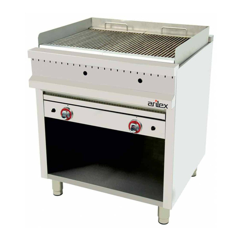
arilex 35FRYGR User manual


ÍNDICE (ES)
Condiciones de la garantía..............................................................2
1. Ficha técnica del aparato................................................................3
2. Instrucciones técnicas de la instalación para el instalador..........4
2.1 Instrucciones previas........................................................................4
2.2 Lugar de instalación y jación del aparato........................................4
2.3 Tipo de gas utilizado.........................................................................4
2.4 Conexión del aparato a la red general de gas..................................5
2.5 Cambio del tipo de gas.....................................................................6
2.6 Regulación primaria del aire.............................................................6
2.7 Regulación del mínimo......................................................................6
2.8 Puesta en marcha del aparato..........................................................7
3. Instrucciones de uso y mantenimiento para el usuario................7
3.1 Precauciones previas........................................................................7
3.2 Encendido y apagado del aparato....................................................7
3.3 Limpieza, conservación y mantenimiento.........................................7
4. Posibles averías................................................................................8
5. Lista de piezas que pueden ser necesario cambiar......................9
6. Comprobación y funcionamiento del aparato................................9
7.- Características.................................................................................9
7.1.- Frytops..........................................................................................9
7.2.- Frytops + Barbacoas...................................................................10
7.3.- Barbacoas...................................................................................10
1

2
Este aparato debe instalarse de acuerdo con las reglamentaciones en vigor, y debe
utilizarse únicamente en lugares sucientemente ventilados.
Consultar las instrucciones antes de instalar y utilizar este aparato.
Se recomienda comprobar el aparato antes de su instalación y vericar que no ha
sufrido daño alguno por el transporte.
El fabricante no se responsabiliza si el aparato es instalado sin seguir las instrucciones
de instalación o si el usuario actúa sin tener en cuenta las instrucciones del manual.
Las operaciones de instalación y mantenimiento se realizarán por personal técnico
cualicado.
Estas instrucciones sólo son válidas si el símbolo del país gura sobre el aparato, en
caso contrario debe pedirse las instrucciones correspondientes.
Se recuerda que las piezas que han sido protegidas por el fabricante y su mandatario no
deben manipularse por el instalador ni el usuario.
CONDICIONES DE LA GARANTIA
La frytop y la barbacoa tienen una garantía de un año desde la fecha de compra ante
cualquier anomalía de fabricación. Son causa de extinción e garantía:
- Cualquier avería causada por el desgaste normal al paso del tiempo
- Cualquier avería causada por una mala utilización del aparato o por hacer caso omiso
del manual de instrucciones
En general, cualquiera con causa no atribuible al fabricante

1. FICHA TÉCNICA DEL APARATO
TIPO A MODELO MODELO MODELO
Cat: 112H3+ FryTop Barbacoa + Parrilla Vasca Frytop + Parrilla Vasca
Gas Pre-
sión
(Mbar)
Consu-
mo o
Caudal
35FRYGC 70FRYGC 100FRYGC 35BAR 60BAR 90BAR 70FRYGCB 100FRYGCB
35FRYGR 70FRYGR 100FRYGR 35VAS 70VAS 100VAS 70FRYGRB 100FRYGRB
G20 20 (Hi) kW 5.2 10.4 15.6 6.2 12.4 18.6 11.4 16.5
m3 / h 0.50 1.00 1.50 0.62 1.24 1.86 1.12 1.62
G30 28-30 (Hi) kW 5.2 10.4 15.6 6.4 12.8 19.2 11.6 16.6
m3 / h 0.14 0.28 0.42 0.18 0.36 0.54 0.32 0.46
G31 37 (Hi) kW 5.2 10.4 15.6 6.5 13.0 19.5 11.7 16.9
m3 / h 0.18 0.36 0.54 0.22 0.44 0.66 0.40 0.58
TIPO A MODELO MODELO MODELO
Cat: 3BP/P FryTop Barbacoa + Parrilla Vasca Frytop + Parrilla Vasca
Gas Pre-
sión
(Mbar)
Consu-
mo o
Caudal
35FRYGC 70FRYGC 100FRYGC 35BAR 60BAR 90BAR 70FRYGCB 100FRYGCB
35FRYGR 70FRYGR 100FRYGR 35VAS 70VAS 100VAS 70FRYGRB 100FRYGRB
G30 50 (Hi) kW 5.50 11.0 16.5 7.5 15.0 22.5 13.0 18.5
m3 / h 0.14 0.28 0.32 0.18 0.36 0.54 0.32 0.48
G31 50 (Hi) kW 4.72 9.4 14.1 6.8 13.6 20.4 11.5 16.2
m3 / h 0.16 0.32 0.48 0.20 0.40 0.60 0.36 0.52
3

2. INSTRUCCIONES TÉCNICAS DE INSTALACIÓN PARA EL
INSTALADOR
La instalación de las Planchas de asar, deberá ser efectuada única y exclusivamente
por personal autorizado y en base a la normativa vigente, según la normativa del país
de destino.
2.1. INSTRUCCIONES PREVIAS
- Estas instrucciones sólo son validas si el símbolo del país gura sobre el aparato
- Las planchas de asar deben instalarse sobre un mostrador y a una distancia mínima
de las paredes laterales de 150 mm teniendo en cuenta que tanto el mostrador como
las paredes deben ser de materiales no combustibles y poder soportar un incremento
de temperatura de 65ºC
- Se comprobará que todos los elementos que componen el aparato se encuentran
perfectamente situados y que debido al transporte no han sufrido desajustes.
2.2. LUGAR DE INSTALACIÓN Y FIJACIÓN DEL APARATO
- Será un lugar completamente limpio
- Estará convenientemente ventilado tanto en la entrada de aire como en la evacuación
de los productos de la combustión de acuerdo con las reglamentaciones de cada país,
colocando el aparato bajo una campana de extracción de al menos 500 m3/h.; Teniendo
en cuenta que si hubiera más aparatos a gas instalados la cantidad de aire necesario es
de 10 m3/h por kW instalado.
- Tendrá las dimensiones mínimas necesarias para colocar la plancha sobre ella
cumpliendo con las distancias de seguridad, de temperatura y combustibilidad.
- Las planchas se instalará, solamente en un lugar con ventilación suciente para impedir
la formación de concentraciones inadmisibles de sustancias nocivas para la salud
- Las planchas no requieren una jación especial, se colocaran directamente sobre la
supercie comprobando que quede nivelada y estabilizada
2.3. TIPO DE GAS UTILIZADO
Salvo petición especica los aparatos están regulados para el funcionamiento con
G.L.P. “Butano 28-30 mbar o Propano 37 mbar” , dicha información está indicada en la
placa de características que esta situada en el lateral izquierdo del aparato al lado de
la entrada de gas.
Para adaptarlos a gas natural habrá que proceder al cambio de los inyectores y del
porta-gomas, Según el apartado 2.5 CAMBIO DEL TIPO DE GAS.
4

2.4. CONEXIÓN DEL APARATO A LA RED GENERAL DE
GAS
Una vez realizada la comprobación de los datos de gas, el instalador se encargará de la
conexión del a la red general de suministro de gas según las normas vigentes en el país
de destino, cumpliendo como mínimo los siguientes requerimientos:
- El punto de conexión será fácilmente accesible y debe permitir el libre desplazamiento
de las herramientas de apriete.
- La conexión de entrada debe llevar una rosca conforme a las recomendaciones dadas
en las normas ISO 228-1 ó EN 10226-1 ó EN 10226-2. O un bicono.
- La tubería con la conexión de alimentación de entrada al aparato se jará de forma
rígida al cuerpo del aparato.
- Si se utiliza tubo exible de alimentación de gas tendrá una longitud máxima de 1,5 m,
deberá cumplir los requisitos nacionales en vigor y debe examinarse periódicamente y
sustituirse cuando sea necesario.
Los tipos de conexión que se utilizan en los diferentes países se indican en la tabla T-1.
Para los aparatos de categoría I3 la conexión no se realizará obligatoriamente por medio
de una conexión roscada o de un bicono, puede hacerse también con junta cónica o por
junta plana.
TABLA T-1
Categoría I3B/P,I3+,IP Otras Categorías
Con rosca Otras Con rosca Otras
Países EN10226-1
EN10226-2
ISO
228-1
Conexiones
según 2.4
EN10226-1
EN10226-2
ISO 228-1 Conexio-
nes con
bicono
Alemania Si Si Si
Austria Si Si Si
Bélgica Si Si Si Si
Dinamarca Si Si Si Si
España Si Si Si Si Si
Finlandia Si Si Si Si
Francia Si Si Si Si Si
Grecia
Irlanda Si Si Si
Islandia
Italia Si Si
Luxemburgo
Noruega Si Si Si
Países Bajos Si Si
Portugal Si Si Si Si Si
UK Si Si Si Si
Suecia
Suiza Si Si Si
5

2.5. CAMBIO DEL TIPO DE GAS
Debe hacerlo un instalador autorizado
ATENCION: Si se modica el tipo de gas o presión, se deberá colocar la placa de
características que se adjunta en los recambios en la parte trasera de la plancha,
sobreponiéndose a la etiqueta anterior, permitiendo así identicar sin ningún tipo de
ambigüedad el estado de la plancha después de la modicación.
QUEMADOR BARBACOA
1º Sacar los 4 Tornillos A
2º Sacar el quemador B
3º Sacar inyector C
4º Colocar el inyector nuevo
5º Volver a colocar quemador B
6º Colocar Tornillos A
Proceder de la misma forma para el resto de
quemadores
QUEMADOR FRYTOP
1º Darle la vuelta a la plancha
2º Sacar inyector A
3º Proceder a cambiar el inyector
2.6. REGULACIÓN DEL AIRE PRIMARIO
En este aparato no es necesaria la regulación del aire primario
2.7. REGULACIÓN DEL MÍNIMO
Encender el quemador y situar el pomo en la llama pequeña o en el nº 1 para válvula
termostática. Sacar el pomo del grifo “tirando suavemente de él”; quedara a la vista un
tornillo situado en el lado izquierdo del eje.
Con un destornillador tipo regleta girar el tornillo en sentido horario para reducir la altura
de la llama y en sentido contrario para aumentar.
6

2.8. PUESTA EN MARCHA DEL APARATO
a.- Colocar el modulo encima de la plancha, haciendo
coincidir los tetones del modulo con los agujeros de los
soportes del modulo.
b.- Abrir el paso del gas de la red general de suministro
2.- Encendido
- Presionar y girar el mando a la posición de dos llamas
- Levantar o extraer el recolector
- Pulsar el piezo eléctrico repetidas veces hasta el encendido del quemador.
- Mantener presionado el pomo durante 10 segundos, para dar tiempo a que actúe la
válvula de seguridad
- Recolocar la grasera a su posición inicial
3.- Apagado: Para realizar el apagado del aparato es suciente con girar el mando hasta
la posición de apagado (0).
4.- Se recomienda cerrar el paso del gas de la red general de suministro.
3. INSTRUCCIONES DE USO Y MANTENIMIENTO PARA EL
USUARIO
3.1. PRECAUCIONES PREVIAS
- Este aparato es únicamente de uso profesional y debe ser utilizado por personal
cualicado.
- Para realizar el mantenimiento, limpieza o reparaciones se debe cerrar la llave de gas.
Se realizaran vericaciones periódicas, de acuerdo con los reglamentos en vigor en el
país en que el aparato vaya a ser instalado.
El fabricante no se hace responsable de los daños ocasionados del uso de la maquina
con cualquier modicación, eliminación o falta de mantenimiento de sus componentes
realizara sin autorización previa y expresa del fabricante.
Este es un aparato que tiene supercies muy calientes en particular el peto y debe
evitarse el contacto del mismo sin el uso de guantes.
3.2. ENCENDIDO Y APAGADO DEL APARATO
Ver apartado 2.8 punto 2.- Encendido
3.3. LIMPIEZA, CONSERVACIÓN Y MANTENIMIENTO
La limpieza diaria al nal del trabajo garantiza un buen funcionamiento y alarga la vida
del aparato.
Las planchas están diseñadas de forma que sean fácilmente desmontables y accesibles
para su conservación y limpieza. NO SE HARA NUNCA LA LIMPIEZA POR CHORRO
A PRESIÓN.
7

Supercies de acero inoxidable
El envolvente de las planchas de asar está construido en acero inoxidable, material de
excelente calidad y durabilidad. Limpiando con un detergente adecuado diariamente se
mantendrá en perfecto estado.
Plancha superior y Cromo
La supercie de la plancha debe estar siempre limpia de residuos sólidos. La grasera
permite depositar dichos residuos en su interior. Al nalizar se aconseja pasar un trapo
para mantenerla en perfecto estado. Las placas de cromo solo deben limpiarse con agua,
NUNCA DEBEN UTILIZARSE DESENGRASANTES NI OTROS PRODUCTOS DE
LIMPIEZA PUESTO QUE PODRIAN DAÑAR EL CROMO DE FORMA IRREVERSIBLE.
Grasera.
Después de cada uso se extraerá la grasera vaciando su contenido
ATENCION: La grasera solo debe ser manipulada cuando este fría o en su defecto
utilizando guantes de protección para evitar quemaduras.
Rejilla Superior Barbacoa
Al nalizar la jornada de trabajo se recomienda pasar un trapo para limpiar.
Piedra Volcánica.
Como mínimo una vez al mes debemos limpiar el carbón y los quemadores una vez a
la semana ya que la piedra volcánica de las barbacoas genera polvo que puede llegar a
obturar los oricios de salida del quemador por lo cual es necesario limpiar regularmente
dichos oricios con un cepillo metálico para evitar su obstrucción y permitir una buena
combustión.
Para lavar la piedra volcánica con agua y jabón y aclarándola posteriormente para que
no deje restos de jabón en caso de tener que cambiarla debe utilizarse lava volcánica
de un tamaño de entre 2cm a 4 cm y la cantidad a colocar es de 4 kilos por mando
repartiéndolo de tal forma que no queden huecos.
- CONSERVACION Y MANTENIMIENTO
Anualmente debe realizarse una limpieza general del aparato. En ella se deberá tener
en cuenta la limpieza de los inyectores, de las válvulas y el engrase de las mismas.
Para engrasar las válvulas proceder a retirar el mando “tirando suavemente de él”
limpiar el eje con una paño, y engrasar con grasa ligera el eje y volver a colocar el
mando.
4. POSIBLES AVERIAS
No se encienden los quemadores
a.- No llega combustible, comprobar que el grifo de la red de suministro está abierta y
en caso de utilizar botella, comprobar que está llena.
8
La llama desprende gases negros y presenta color amarillo fuerte
a.- Obstrucción del inyector del quemador, Proceder a limpiar
b.- Quemador sucio, Proceder a limpiar
c.- Falta de aire primario, comprobar que el aparato tiene los pies colocados y existe
una abertura entre la encimera y el mueble y que nada este cerrando la entrada y salida
de aire.
ESTE ES UN PROBLEMA GRAVE YA QUE PUEDE GENERAR UNA MALA
COMBUSTION GENERANDO EXCESO DE MONOXIDO U OTROS GASES NOCIVOS
Al dejar de presionar el grifo del mando se apaga el quemador
a.- Debe mantener presionado como mínimo 15 segundos.
b.- Termopar defectuoso, reemplazar termopar.
El quemador de la barbacoa no se enciende todo
a.- No se ha limpiado el quemador de la barbacoa y se han obturado oricios del
quemador , proceder a limpiarlo según se indica en el apartado 3.3. Piedra Volcánica
5. LISTA DE PIEZAS QUE PUEDE SER NECESARIO
REMPLAZAR
Piezo de encendido.- Desenroscar el piezo soltar el cable y tirar de él.
Inyector.- Ver apartado 2.4 Cambio de tipo de gas
Termopar.- En el lado del soporte quemador “desenroscar”, en el lado del grifo
desenroscar.
Bujía,- En el lado quemador soltar el muelle que la sujeta y en el lado del piezo tirar de
él. “Es tipo faston”
6. COMPROBACION DEL FUNCIONAMIENTO DEL
APARATO
Una vez puesto en marcha, se realizará una comprobación del funcionamiento siguiendo
siempre las indicaciones del país de destino para el instalador.
Es responsabilidad del instalador realizar estas comprobaciones según la reglamentación
en vigor.
9

Modelos Ud. 35FRY-
GR
70FRY-
GR
100FRY-
GR
35FRY-
GC
70FRY-
GC
100FRY-
GC
Dimensión
Exterior
Largo mm 340 678 1010 340 678 1010
Ancho mm 570+40 570+40 570+40 570+40 570+40 570+40
Alto mm 310+Pies 310+Pies 310+Pies 310+Pies 310+Pies 310+Pies
Pies mm 30 30 30 30 30 30
Placa - Parrilla Placa Placa Placa Placa Placa Placa
Largo mm 330 670 1006 330 670 1006
Ancho mm 492 492 492 492 492 492
Alto mm 20 20 20 20 20 20
Tipo Placa Recti-
cada
Recti-
cada
Recti-
cada
Cromo
Duro
Cromo
Duro
Cromo
Duro
Parrilla No No No No No No
Potencia
G.N. 20 mbar kW 5,5 11 16,5 5,5 11 16,5
G.L.P 30 mbar kW 5,5 11 16,5 5,5 11 16,5
G.L.P. 50 mbar kW 5,8 11,6 17,4 5,8 11,6 17,4
Componentes
Válvula
Manual
Ud. 1 2 3 - - -
Válvula
Termostatica
Ud. - - - 1 2 3
Quemador
Tubular
Ud. - - - - - -
Quemador
Pescado
Ud. 2 4 6 2 4 6
Piezos Ud. 1 2 3 1 2 3
10
7. CARACTERÍSTICAS
7.1. FRYTOPS

Modelos Ud. 70FRYGRB 100FRYGRB 70FRYGCB 100FRYGCB
Dimensión
Exterior
Largo mm 678 1010 678 1010
Ancho mm 570+40 570+40 570+40 570+40
Alto mm 30 30 30 30
Pies mm 30 30 30 30
Placa - Parrilla Parrilla + Placa Parrilla + Placa Parrilla + Placa Parrilla + Placa
Largo mm 330 670 330 670
Ancho mm 492 492 492 492
Alto mm 20 20 20 20
Tipo Placa Recticada Recticada Cromo Duro Cromo Duro
Parrilla 500x 300 500x 300 500x 300 500x 300
Potencia
G.N. 20 mbar kW 13 18,5 13 18,5
G.L.P 30 mbar kW 13 18,5 13 18,5
G.L.P. 50 mbar kW 13,7 19,5 13,7 19,5
Componentes
Válvula
Manual
Ud. 2 3 - -
Válvula
Termostatica
Ud. - - 2 3
Quemador
Tubular
Ud. 2 2 2 2
Quemador
Pescado
Ud. 2 4 2 4
Piezos Ud. 1 2 1 2
11
7.2. FRYTOPS + BARBACOAS

Modelos Ud. 35VAS 70VAS 100VAS 35BAR 60BAR 90BAR
Dimensión
Exterior
Largo mm 340 678 1010 350 600 900
Ancho mm 580 580 580 457 457 457
Alto mm 310+Pies 310+Pies 310+Pies 220+Pies 220+Pies 220+Pies
Pies mm 30 30 30 20 20 20
Placa - Parrilla Parrilla Parrilla Parrilla Parrilla Parrilla Parrilla
Largo mm 1*280 2*280 3*280 280 530 830
Ancho mm 530 530 530 430 430 430
Alto mm 40 40 40 40 40 40
Potencia
Gas Natural kW 7,2 14,4 7,2 14.4 21,6
Gas G.L.P. kW 7 14,1 7 14.1 21,2
Componentes
Válvulas Ud. 1 2 3 1 2 3
Quemadores Ud. 2 4 6 2 4 6
Termostato de
seguridad
Ud. - - - - - -
Piezos Ud. - - - - - -
12
7.3. BARBACOAS

13
INDEX (EN)
Warranty conditions.....................................................................14
1.- Technical sheet..............................................................................15
2.- Technical installation instructions for the installer....................16
2.1.- Preliminary instructions.................................................................16
2.2.- Place of installation and xing of the device.................................16
2.3.- Type of gas used..........................................................................16
2.4.- Connection of the appliance to the general gas network..............17
2.5.- Change of gas type.......................................................................18
2.6.- Primary air regulation....................................................................18
2.7.- Minimum regulation......................................................................18
2.8.- Turning on the device....................................................................18
3.- Instructions for use and maintenance for the user....................19
3.1.- Preliminary precautions................................................................19
3.2.- Turning the device on and o........................................................19
3.3.- Cleaning, storage and maintenance.............................................19
4.- Possible breakdowns....................................................................19
5.- List of spare parts that may be necessary to replace................21
6.- Assembly........................................................................................21
7.- Features.........................................................................................22
7.1.- Frytops..........................................................................................22
7.2.- Frytops + Barbacues....................................................................23
7.3.- Barbecues....................................................................................24

14
This appliance must be installed in accordance with current regulations, and must only
be used in suciently ventilated places.
Consult the instructions before installing and using this appliance.
It is recommended to check the appliance before installation and verify that it has not
suered any damage during transport.
The manufacturer is not responsible if the appliance is installed without following the
installation instructions or if the user acts without taking into account the instructions in
the manual.
Installation and maintenance operations will be carried out by qualied technical
personnel.
These instructions are only valid if the country symbol appears on the device, otherwise
the corresponding instructions must be requested.
It is recalled that the parts that have been protected by the manufacturer and its agent
must not be manipulated by the installer or the user.
WARRANTY CONDITIONS
The frytop and the barbacue are guaranteed for one year from the date of purchase
against any manufacturing anomaly. They are cause of extinction of the guarantee:
- Any breakdown caused by normal wear over time
- Any breakdown caused by misuse of the appliance or by ignoring the instruction manual
- In general, anyone with cause not attributable to the manufacturer

1. TECHNICAL SHEET
TYPE A MODEL MODEL MODEL
Cat: 112H3+ FryTop Barbecue + Basque Grill Frytop + Basque Grill
Gas Pres-
sure
(Mbar)
Consump-
tion or
ow
35FRYGC 70FRYGC 100FRYGC 35BAR 60BAR 90BAR 70FRYGCB 100FRYGCB
35FRYGR 70FRYGR 100FRYGR 35VAS 70VAS 100VAS 70FRYGRB 100FRYGRB
G20 20 (Hi) kW 5.2 10.4 15.6 6.2 12.4 18.6 11.4 16.5
m3 / h 0.50 1.00 1.50 0.62 1.24 1.86 1.12 1.62
G30 28-30 (Hi) kW 5.2 10.4 15.6 6.4 12.8 19.2 11.6 16.6
m3 / h 0.14 0.28 0.42 0.18 0.36 0.54 0.32 0.46
G31 37 (Hi) kW 5.2 10.4 15.6 6.5 13.0 19.5 11.7 16.9
m3 / h 0.18 0.36 0.54 0.22 0.44 0.66 0.40 0.58
TYPE A MODEL MODEL MODEL
Cat: 3BP/P FryTop Barbecue + Basque Grill Frytop + Basque Grill
Gas Pres-
sure
(Mbar)
Con-
sumption
or ow
35FRYGC 70FRYGC 100FRYGC 35BAR 60BAR 90BAR 70FRYGCB 100FRYGCB
35FRYGR 70FRYGR 100FRYGR 35VAS 70VAS 100VAS 70FRYGRB 100FRYGRB
G30 50 (Hi) kW 5.50 11.0 16.5 7.5 15.0 22.5 13.0 18.5
m3 / h 0.14 0.28 0.32 0.18 0.36 0.54 0.32 0.48
G31 50 (Hi) kW 4.72 9.4 14.1 6.8 13.6 20.4 11.5 16.2
m3 / h 0.16 0.32 0.48 0.20 0.40 0.60 0.36 0.52
15

2. TECHNICAL INSTALLATION INSTRUCTIONS FOR THE
INSTALLER
The installation of the grilling plates, must be carried out only and exclusively by
authorized personnel and based on current regulations, according to the regulations of
the country of destination.
2.1. PRELIMINARY INSTRUCTIONS
- These instructions are only valid if the country symbol appears on the device
- The grilling plates must be installed on a counter and at a minimum distance from the
side walls of 150 mm taking into account that both the counter and the walls must be
non-combustible materials and able to withstand a temperature increase of 65ºC
- It will be veried that all the elements that compose the apparatus are perfectly located
and that due to the transport they have not suered any maladjustments.
2.2. INSTALLATION PLACE
- It must be a completely clean place
- It must be properly ventilated both in the air inlet and in the evacuation of the products
of combustion in accordance with the regulations of each country, placing the appliance
under an extraction hood of at least 500 m3 / h .; Taking into account that if there were
more gas appliances installed, the amount of air required is 10 m3 / h per kW installed.
- It must have the minimum dimensions necessary to place the iron on it complying with
the safety, temperature and combustibility distances.
- The plates should only be installed in a place with sucient ventilation to prevent the
formation of inadmissible concentrations of substances harmful to health.
- The plates do not require a special xation, they should be placed directly on the
surface checking that they are level and stabilized
2.3. TYPE OF GAS USED
Unless specied, the devices are regulated for operation with G.L.P. “Butane 28-30 mbar
or Propane 37 mbar”, this information is indicated on the rating plate that is located on
the left side of the appliance next to the gas inlet.
To adapt them to natural gas, it will be necessary to change the injectors and the rubber
holder, according to section 2.5 CHANGE OF THE TYPE OF GAS.
16

2.4. CONNECTION OF THE DEVICE TO THE GENERAL GAS
NETWORK
Once the gas data verication has been carried out, the installer will be responsible for
connecting to the general gas supply network according to the regulations in force in the
country of destination, fullling at least the following requirements:
- The connection point must be easily accessible and must allow free movement of the
tightening tools.
- The input connection must have a thread in accordance with the recommendations
given in ISO 228-1 or EN 10226-1 or EN 10226-2. Or a bicone.
- The pipe with the input power connection to the appliance shall be xed rigidly to the
body of the appliance.
- If gas supply hose is used, it will have a maximum length of 1.5 m, it must comply with
the national requirements in force and must be periodically examined and replaced when
necessary.
The types of connection used in the dierent countries are indicated in chart T-1.
For category I3 devices the connection will not necessarily be made by means of a
threaded connection or a biconical connection, it can also be done with a conical joint
or by a at joint.
CHART T-1
Category I3B/P,I3+,IP Other Categories
Threaded Other Threaded Other
Countries EN10226-1
EN10226-2
ISO
228-1
Connec-
tions accor-
ding 2.4
EN10226-1
EN10226-2
ISO 228-1 Connec-
tions with
bicone
Germany Yes Yes Yes
Austria Yes Yes Yes
Belgium Yes Yes Yes Yes
Denmark Yes Yes Yes Yes
Spain Yes Yes Yes Yes Yes
Finland Yes Yes Yes Yes
France Yes Yes Yes Yes Yes
Greece
Ireland Yes Yes Yes
Iceland
Italy Yes Yes
Luxembourg
Norway Yes Yes Yes
Netherlands Yes Yes
Portugal Yes Yes Yes Yes Yes
UK Yes Yes Yes Yes
Sweden
Switzerland Yes Yes Yes
17

2.5. CHANGE OF THE TYPE OF GAS
It must be done by an authorized installer
ATTENTION: If the type of gas or pressure is modied, the nameplate that is attached to
the spare parts on the back of the plate must be placed, overlapping the previous label,
thus allowing to identify without any ambiguity the state of the iron after the modication.
BARBECUE BURNER
1º Remove the 4 screws A
2º Remove burner B
3º Remove the injector C
4º Place the new injector
5º Replace burner B
6º Place screws A
Proceed in the same way for the rest of
the burners
FRYTOP BURNER
1º Turn the griddle over
2º Remove the injector A
3º Proceed to change the injector
2.6. PRIMARY AIR REGULATION
In this device it is not necessary to regulate the primary air.
2.7. REGULATION OF THE MINIMUM
Turn on the burner and place the knob on the small ame or on the No. 1 for thermostatic
valve. Remove the knob from the tap “gently pulling on it”; A screw located on the left
side of the shaft will be visible.
Use a slotted screwdriver to turn the screw clockwise to reduce the height of the ame
and counterclockwise to increase it.
18

2.8. TURNING ON THE DEVICE
a.- Place the plate on top of the griddle, making
the plate lugs coincide with the holes in the
griddle supports.
b.- Open the gas passage of the general supply
network.
2.- Ignition.
- Press and turn the knob to the position of two ames.
- Lift or remove the fat collector.
- Press the electric piezo repeatedly until the burner ignites..
- Press and hold the knob for 10 seconds, to allow time for the safety valve to act.
- Relocate the fat collector to its initial position.
- Regulate the ame of the burner to the desired power, the thermostatic valves are
numbered from 1 to 8, with 1 being the minimum power and 8 the maximum.
3.- Switching o: To switch o the appliance, simply turn the knob to the OFF position (0).
4.- It is recommended to close the gas passage of the general supply network.
3. INSTRUCTIONS FOR USE AND MAINTENANCE FOR THE
USER
3.1. PRELIMINARY PRECAUTIONS
- This device is for professional use only and must be used by qualied personnel.
- To perform maintenance, cleaning or repairs, the gas cock must be closed.
Periodic checks will be carried out, in accordance with the regulations in force in the
country in which the device is to be installed.
The manufacturer is not responsible for the damages caused by the use of the machine
with any modication, elimination or lack of maintenance of its components carried out
without prior and express authorization of the manufacturer.
This is a device that has very hot surfaces in particular the breastplate and contact
should be avoided without the use of gloves.
3.2. TURNING THE DEVICE ON AND OFF
See section 2.8 point 2.- Ignition
19
This manual suits for next models
15
Table of contents
Languages:
Other arilex Grill manuals