ARJO HUNTLEIGH Minuet 2 160 User manual

MINUET 2
INSTRUCTIONS FOR USE
...with people in mind
746-574-AM-1 • 10/2015

Design Policy and Copyright
® and ™ are trademarks belonging to the ArjoHuntleigh group of companies.
© ArjoHuntleigh 2004
As our policy is one of continuous development, we reserve the right to modify
designs without prior notice. The content of this publication may not be copied
either wholly or in part without the consent of ArjoHuntleigh.
Revised 10/2015
746-574-AM-1 1

Contents
Warnings, Cautions and Notes ...............................................................3
General Warnings and Cautions.............................................................4
1. Introduction..........................................................................6
Product description.................................................................................6
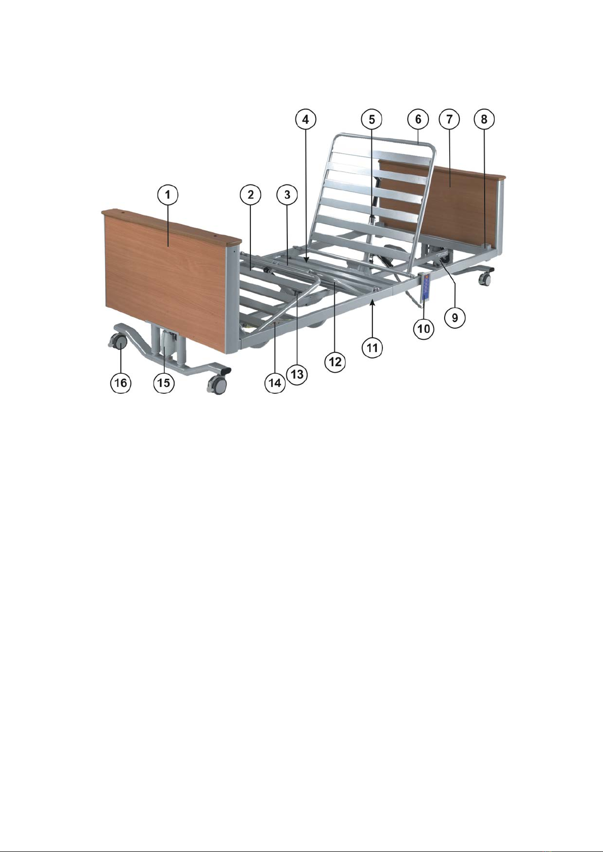
Product overview ....................................................................................7
2. Applications.........................................................................8
Intended use...........................................................................................8
Indications...............................................................................................8
Contra-indications...................................................................................9
3. Assembly and Installation.................................................11
Mattresses ............................................................................................12
Assembling the bed ..............................................................................14
4. Operation............................................................................20
Control handset.....................................................................................20
Brakes and castors...............................................................................22
Kneebreak angle...................................................................................23
Extending the bed.................................................................................24
5. Accessories – Fitting and Operation................................25
Full-length side rails..............................................................................27
Side rail height extensions....................................................................29
Folding steel side rails...........................................................................31
Pads for full length side rails CM-ACC03 & CM-ACC26 .......................34
Lifting poles CM-ACC09........................................................................35
Mobility support handle CM-ACC11 & CM-ACC12...............................38
IV pole CM-ACC14 ...............................................................................40
Mattress pump bracket CM-ACC15 ......................................................41
Urine bag holder CM-ACC17................................................................42
Egress assist rail...................................................................................43
Mattress retainers CM-ACC24..............................................................47
6. Dismantling the Bed..........................................................48
7. Cleaning .............................................................................51
8. Care and Preventive Maintenance....................................52
Preventive maintenance........................................................................52
Troubleshooting guide ..........................................................................54
9. Warranty and Service........................................................55
10. Technical Data ...................................................................56
11. Electromagnetic Compatibility (EMC)..............................59
746-574-AM-1 2

Warnings, Cautions and Notes
WARNINGS given in this manual identify possible hazards in procedures or
conditions, which if not correctly followed, could result in death, injury or other
serious adverse reactions.
Cautions given in this manual identify possible hazards in procedures or
conditions, which if not correctly followed, could result in equipment damage
or failure.
Notes given in this manual (indicated by ) are used to explain or amplify a
procedure or condition.
Indicates an optional item.
746-574-AM-1 3

General Warnings and Cautions
WARNING
Keep these instructions in a safe place – you may need to refer to them
later on.
These instructions are mandatory for the safe and effective use of this
product, including the safety of patients and carers.
Read and understand these instructions before assembling or operating
the bed. You must be trained in the proper use of this product, its
functions and controls, and any accessories. The bed must be installed
and operated in accordance with information in these instructions.
Unauthorised modifications or repairs to this product may affect its
safety and will invalidate any warranty. ArjoHuntleigh accepts no liability
for any incident, accident or reduction in performance which may occur
as a result of such repairs or modifications.
Do not smoke or use naked flames near this equipment and do not
expose it to extremes of temperature.
Do not use accessories that have not been designed and approved for
use with the bed. Do not connect the bed to other equipment unless
specified in these instructions.
This product contains small parts that may present a choking hazard to
children if inhaled or swallowed.
Keep pets and children away from the bed unless they are supervised by
an adult.
Electrical equipment can be hazardous if misused.
Do not use electrically powered beds in the presence of flammable
gases such as anesthetic agents.
Ensure that the bed is assembled and installed in accordance with the
instructions given in this manual.
Do not use this bed for transporting patients.
Always use a mattress of the correct size and type. Suitable pressure
reducing and pressure relieving mattresses are available from
ArjoHuntleigh.
Before operating the bed, make sure that the patient is safely positioned
to avoid entrapment or imbalance.
When operating the bed, make sure its movement is not restricted by
obstacles such as bedside furniture.
To reduce the risk of injury due to falls, lower the bed to minimum height
whenever the patient is left unattended.
Make sure the control handset cord is positioned to avoid a
strangulation risk.
746-574-AM-1 4

WARNING
Do not allow the power cord to trail on the floor in such a way that it may
cause a trip hazard.
Do not leave the Minuet 2 bed and accessories for extended periods of
time in humid or wet areas.
Take care to ensure that the power cord is not damaged by the bed or
other objects being moved over it.
When routing cables from other equipment take care to prevent
squeezing cables between parts of the bed.
This product complies with the requirements of applicable standards for
electromagnetic compatibility (EMC). However, medical electrical
equipment requires special precautions regarding EMC and should be
installed and used in accordance with the information in Chapter 11 of
these instructions.
Wireless communications equipment such as wireless computer
network devices, mobile phones, cordless telephones and their base
stations, walkie-talkies, etc. may affect this product. The bed should be
kept at least 2.3 metres (7.5ft) away from such equipment to minimise
the possibility of interference.
Do not leave the patient in the tilt position unattended.
746-574-AM-1 5

1. Introduction
Product description
The ArjoHuntleigh Minuet®2 is a bed with electrically operated functions,
intended for use in the care of elderly or disabled persons.
It is designed to be dismantled into sections for ease of transportation, but can
be easily assembled with a minimum of tools.
There are two basic models in the Minuet 2 range:
Model 160 Four section bed with electrically adjustable height, backrest
and leg elevation.
Model 161 Model 160 with the addition of head down and foot down tilt.
WARNING
The tilt function on model 161 does not meet the requirements of the
Trendelenburg position. The bed cannot be used in applications that
need the patient to be put in the Trendelenburg position.
The model number and serial number can be found on the
specification label, located at the head end of the mattress platform.
Specification label
Features
•Push-button control for all electrical functions
•Electrically operated adjustment of height, backrest angle and leg
elevation
•Manual adjustment of kneebreak angle
•Extending mattress platform
•Castors with integral brakes
•Backup battery to allow operation during power failure
A range of accessories is available, including side rails and lifting poles. The
installation and use of these items is described in Chapter 5.
746-574-AM-1 6

Product overview
1. Foot end section 9. Head end actuator
2. Calf (lower leg) section 10. Control handset
3. Seat section 11. Thigh (upper leg) section
4. Control box / backup battery 12. Leg section actuator
5. Backrest actuator 13. Leg section ratchet
6. Backrest section 14. Foot end actuator
7. Head end section 15. Castor with brake lever
8. Lifting pole / accessory socket
746-574-AM-1 7

2. Applications
WARNING
To ensure the patient can use the bed safely, their age, size and
condition should be assessed by a clinically qualified person.
Intended use
Model 160 is suitable for use in the following areas:
•Long term medical care where medical supervision
is required and monitoring is provided if necessary,
e.g. nursing homes and geriatric facilities.
•A domestic area, i.e. home healthcare.
Model 161 is suitable for use in the following area:
•Long term medical care where medical supervision
is required and monitoring is provided if necessary,
e.g. nursing homes and geriatric facilities.
Indications
The bed is appropriate for situations where assistance
is required in positioning the patient, or in reducing
lifting and manual handling stresses on the carer.
The profiling mattress platform allows the patient to be
supported in an upright sitting position. The enhanced
support this provides helps to reduce shear and
interface pressure on the patient.
The head down Tilt option can be used to increase
blood flow. The bed cannot be used in applications that
need the patient to be put in the Trendelenburg
position. The Maximum tilt angle of the Minuet bed
frame is 10°.
Foot down tilt option can be used to improve patient
confort.
The variable height feature allows the bed to be raised
to provide easy access to the patient for the carer. The
bed can then be lowered to make it easier for the
patient to get into or out of the bed.
746-574-AM-1 8

Contra-
indications
The bed is intended for use by adults and children over
the age of twelve years.
Model 160 is not suitable for use in the following
situations:
•Intensive/critical care provided in a hospital
where 24-hour medical supervision and constant
monitoring is required, e.g. ITU, ICU and CCU.
•Acute care provided in a hospital or other
medical facility where medical supervision and
monitoring is required, e.g. general medical and
surgical wards.
•Outpatient care.
Model 161 is not suitable for use in the following
situations:
•Intensive/critical care provided in a hospital
where 24-hour medical supervision and constant
monitoring is required, e.g. ITU, ICU and CCU.
•Acute care provided in a hospital or other
medical facility where medical supervision and
monitoring is required, e.g. general medical and
surgical wards.
•A domestic area, i.e. home healthcare.
•Outpatient care.
•The use of head down Tilt or foot down Tilt may
be contraindicated for certain medical conditions.
The tilt facility shall only be used under the
guidance of a clinically qualified person after
assessment of the patients condition.
746-574-AM-1 9

This bed is not suitable for patients weighing less than
88lb. (40kg).
The maximum recommended
patient weight is 319lb. (145kg).
The safe working load of the bed is
396lb.(180kg).
The safe working load is calculated as follows (in
accordance with EN 60601-2-52):
Maximum patient weight ………..…… 319lb.(145kg)
Mattress ………………………………….. 44lb.(20kg)
Accessories (including attached loads) 33lb.(15kg)
TOTAL …………………………………… 396lb.(180kg)
WARNING
If the combined weight of the mattress and accessories exceeds
77lb.(35kg), the maximum patient weight must be reduced
accordingly.
The recommended patient height is between
57in.(146cm) and 75in.(190cm).
At the discretion of the carer, patients taller than
75in.(190cm) may be accommodated by extending the
bed - refer to “Extending the bed” in Chapter 4. Ensure
that the patient’s height does not exceed the “extended
length” shown in Chapter 10 Technical Data.
746-574-AM-1 10

3. Assembly and Installation
WARNING
The bed sub-assemblies are heavy. Take appropriate precautions to
prevent injury when moving or lifting them.
Before commencing assembly, make sure the brakes are applied on all
four bed castors.
The assembled bed should be positioned so that the power plug can be
reached easily if it needs to be disconnected from the electricity supply.
Read these instructions and understand them before you begin to assemble
the bed.
Work on a suitable surface (e.g. carpet) to prevent damage to the bed
components.
Make sure you have sufficient space before commencing assembly – the
work area must be large enough to turn the bed upright once it is fully
assembled.
WARNING
Always use the 5mm Allen (hexagon) key supplied when attaching the
socket head screws. Using other tools may result in the screws not
being fully tightened.
The foot end and head end panels are almost identical. The foot end
panel can be identified by the “ArjoHuntleigh” and “Minuet 2” badges
attached to it.
The various parts of the bed are moved by electrical devices called actuators.
Actuators are positioned at either end of the bed and control bed height. Two
actuators are positioned underneath the mattress platform and control the
backrest and leg sections.
The actuators, control handset and power cord, are connected to a control
box, which is fixed onto the backrest actuator together with the backup
battery.
Caution
Before the first use, or if the bed has been unused for more than three
months, connect the bed to the electricity supply for at least 24 hours to
fully recharge the battery.
The bed should be connected to the electricity supply at all times during
normal use to keep the backup battery fully charged.
Failure to follow these guidelines may reduce the life of the battery.
746-574-AM-1 11

Mattresses
WARNING
Always use a mattress of the correct size and type. Incompatible mattresses can
create hazards.
Entrapment hazards may exist when using a very soft mattress, even if it is the
correct size.
Read the instructions for use supplied with the mattress.
Where the maximum patient weight specified for the mattress is different to that
specified for the bed, the lower value applies.
To ensure compliance with EN 60601-2-52, an approved ArjoHuntleigh mattress
should be used. Compliance with this standard when using other mattresses must
be validated by the user.
A label on the mattress platform indicates the supported
mattress height when used without side rails or standard
height side rails:
Mattress size label
If fitted, a label on the side rail will indicate if a different
mattress height can be used safely:
Product Code
Side Rail Type
Mattress
Thickness
CM-ACC00-1.52
Full Length Standard Height Wooden Side Rails (Grey/Beech)
5.9in.(15cm)
CM-ACC00-3.52
Full Length Standard Height Wooden Side Rails (Brown/Beech)
5.9in.(15cm)
CM-ACC01-1.52
Full Length Standard Height Wooden Side Rails (Grey/Cherry)
5.9in.(15cm)
CM-ACC00-1.14
Full Length Extra Height Wooden Side Rails (Grey/Beech)
6.8in.(17.2cm)
CM-ACC00-3.14
Full Length Extra Height Wooden Side Rails (Brown/Beech)
6.8in.(17.2cm)
CM-ACC01-1.14
Full Length Extra Height Wooden Side Rails (Grey/Cherry)
6.8in.(17.2cm)
CM-ACC01-3.14
Full Length Extra Height Wooden Side Rails (Brown/Cherry)
6.8in.(17.2cm)
CM
-ACC02-1.52
Height Extension for Full Length Standard Height Wooden Side
Rails (grey).
Use with overlay between 4.3in.(11cm)-
4.5in.(11.5cm) thick. 5.9in.(15cm)
CM
-ACC02-3.52
Height Extension for Full Length Standard Height Wooden Side
Rails (brown).
Use with overlay between 4.3in.(11cm) -4.5in.(11.5cm) thick. 5.9in.(15cm)
CM-ACC04-1.52
Full Length Standard Height Steel Side Rails
5.9in.(15cm)
CM-ACC06-1.52
Steel 3/4 Length Standard Height Folding Side Rails
5.9in.(15cm)
CM-ACC07-1.52
Steel Extra Height Folding Side Rails
6.8in.(17.2cm)
CM-ACC22-1.52
Egress Assist Rail Standard Height (Grey)
5.9in.(15cm)
CM-ACC23-1.52
Egress Assist Rail Extra Height (Grey)
6.8in.(17.2cm)
746-574-AM-1 12

Mattresses and side
rails
When choosing bed and mattress combinations, it is
important to consider the use of side rails (where fitted)
based on clinical assessment of each individual patient and
in line with local policy.
When assessing the suitability of a mattress for use with side
rails, the following factors should be considered:
•If the bed is installed with standard side rails, a foam
mattress up to 5.9in.(15cm) thick can be used.
•If the bed is installed with extra-height side rails, a foam
mattress up to 6.8in. (17.2cm) thick can be used.
•
Specialist powered air / foam replacement mattresses will
typically envelop the patient when loaded and can
generally be deeper than a foam mattress without
compromising safety. Other makes of specialist mattress
replacement must be assessed individually prior to use to
verify sufficient clearance is maintained.
•Only use a mattress overlay when combined with Full
Length Standard Height Wooden Side rails(CM-ACC00-
1.52, CM-ACC00-3.52 or CM-ACC01-1.52) and Side Rail
Height Extensions CM-ACC02-1.52 or CM-ACC02-
3.52(see page 29). With this combination the bed can be
fitted with a mattress up to 5.9in.(15cm) and an overlay
between 4.3in.(11cm) and 4.5in.(11.5cm).
•To ensure compliance with EN 60601-2-52, an approved
ArjoHuntleigh mattress should be used. Compliance with
this standard when using other mattresses must be
validated by the user.
For more information on suitable mattresses and mattress
replacements, contact your local ArjoHuntleigh office or
approved distributor. A list of ArjoHuntleigh offices can be
found at the back of this manual.
746-574-AM-1 13

Assembling the bed
1
The bed is supplied in four main
sections, fixed together on two transit
brackets (A) for ease of transportation.
Remove the cardboard packing block
and plastic tie between the mattress
platform sections.
Lift the two mattress platform sections off
the transit brackets and lay them on the
floor. The foot end mattress platform
section must be lifted off the transit
brackets before the head end section.
2
Remove the two socket head screws (B) from one of the transit brackets
(A). Remove the second transit bracket, taking care not to allow the end
panel sections to fall. Keep the four socket head screws safe.
Two other socket head screws are installed in holes in the mattress
platform sections – remove these before starting assembly. The six socket
head screws will be used in assembling the bed.
Store the two transit brackets and packaging in a safe place.
WARNING
Do not allow the end panel sections to fall when the transit brackets are
removed.
B
B
A
A
746-574-AM-1 14

3
Lay the head end panel section on the
floor with the two arms on the frame (C)
pointing outwards towards the right as
shown.
Position the bed so that you can work on
the underside of the mattress platform
whilst assembling the bed. This will make
it easier to connect the actuators to the
control box.
4
Slide the two side tubes of the head-end mattress platform section over
the arms on the head end panel assembly.
Place socket head screws into the two holes (D) on the underside of the
head end mattress platform and fix the sections together, installing the
bottom screw first. Tighten both screws firmly.
Use suitable packing material, e.g. cardboard, to raise the mattress
platform sections off the floor by about 1cm. This will help in aligning
the fixing holes correctly.
Unwind the power cord from around the slot (E) on the head end mattress
platform section.
WARNING
Take care not to pinch hands or fingers, or trap any cables, when
sliding the bed sections together.
C
D
E
D
746-574-AM-1 15

5
Assemble the foot end mattress platform to the head end mattress
platform by sliding the two parts together. Make sure the slot (E) in the
head end section locates over the bar in the foot end section (F), and
thread the actuator cables through the central gap as shown.
Place socket head screws into the two holes (G) on the underside of the
foot end mattress platform to fix the sections together, installing the
bottom screw first. Tighten both screws firmly.
6
Assemble the foot end panel to the bed, lining up the fixing holes in the
arms with the fixing holes (H) in the foot end mattress platform section.
Place two socket head screws into the holes to fix the two sections
together, installing the bottom screw first. Tighten both screws firmly.
The foot end mattress platform section has two sets of fixing holes.
Use the ones closest to the crossbar as shown; the other holes (J) are
used if it is necessary to extend the bed.
H
H
J
G
G
F
E
746-574-AM-1 16

7
Pull off the plastic cap (K) from the socket on the head end actuator (L).
Plug the curly cable (M) into the actuator socket.
Replace the cap, making sure it “clicks” into place; this will prevent the
connector being accidentally pulled out of the actuator.
Connect the foot end actuator cable in the same way.
8
The control box is located below
the seat section on the patient’s
right hand side.
Push a flat bladed screwdriver
into the slot (N) to release the
clip holding the cover, while
pulling down the tab (P).
Slide the cover off the control
box and keep it safe.
L
M
K
N
P
746-574-AM-1 17

9
The control box actuator
connections are colour coded.
The bed is supplied with the
backrest actuator (red), head end
actuator (white) and backup battery
already connected.
10
Plug the foot end actuator cable
(green) into the control box.
Plug the leg section actuator cable
(yellow) into the control box.
11
Plug the control handset cable into
the remaining socket.
Make sure that all the plugs
connected to the control box are
pushed fully into their respective
sockets.
12
Press the cables from the
actuators, control handset and
battery into the grooves in the cord
grip (Q) to hold them in place.
Q
746-574-AM-1 18

13
When all the cables are connected,
the control box should look like the
picture on the left.
Make sure the cables lie flat and
are not twisted.
14
Replace the control box cover by
sliding it into position until it “clicks”
into place.
The cables enter the control box
through a slot on the right side of
the cover, next to the cord grip.
Make sure that none of the cables
is trapped or pinched.
15
•Check that the six socket head screws holding the bed sections
together are fully tightened.
•Carefully turn the bed upright onto its castors.
•Remove the plastic ties used to secure the backrest and leg sections to
the bed frame during transit.
•Connect the power plug to a suitable outlet socket.
•Refer to Chapter 4 Operation. Check that all the bed’s electrical
functions operate satisfactorily over their full range of movement. Make
sure that no cables become stretched or trapped in the bed mechanism
during operation.
•Install the mattress retainers on the backrest and leg sections – refer to
Chapter 5 Accessories – Fitting and Operation for fitting instructions.
•Install a suitable, compatible mattress on the bed.
The bed is now ready for use. Read the following Chapters for guidance
on using the bed and the optional accessories.
746-574-AM-1 19
This manual suits for next models
1
Table of contents
Other ARJO HUNTLEIGH Indoor Furnishing manuals