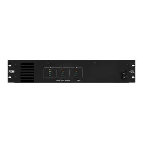
ARMTEL TDA-500 User manual

ENG
TDA-500
Digital Power Amplifier
ARMT.665230.139UM
User Manual
Document version 2 26.40.43.110
2020

armtel.com
© Armtel info@armtel.com

TDA-500 DIGITAL POWER AMPLIFIER
User Manual
armtel.com page 1/28
info@armtel.com © Armtel
ENG
INTRODUCTION
This User Manual is intended for introducing TDA-500 Digital Power Amplifier
manufactured by Armtel LLC, Russia to the User.
TDA-500 Digital Power Amplifier is the equipment of a wired public address (PA)
communication system subscriber and it is intended for work as part of a digital dispatcher
communication system built on the basis of DCN and IPN type centers manufactured by
Armtel, Russia.
Short name of the product – TDA-500.
Operating personnel for TDA-500 shall be appointed by the management at the
installation site.
Duties of the operating personnel shall include maintenance of TDA-500 in accordance
with this User Manual.
The manufacturer reserves the right to make circuit and design changes to the product
that do not affect its parameters.
Example of TDA-500 designation during ordering and in the design documentation of
other products: «TDA-500 Digital Power Amplifier» ARMT.665230.139.
Example of a shortened entry: TDA-500 ARMT.665230.139.

TDA-500 DIGITAL POWER AMPLIFIER
User Manual
page 2/28 armtel.com
ENG
SAFETY PROVISIONS
During installation and operation of TDA-500, observe safety precautions laid out in
local regulations on electrical safety.
ATTENTION:NEVER OPERATE THE PRODUCT WITH A DAMAGED COMMUNICATION
CABLE!
To avoid electric shock, do not:
−turn on the product with a damaged power and communication cables;
−connect and disconnect communication cables only when the power cable is
disconnected.
ATTENTION: DISASSEMBLY OF ARTICLE CONNECTED TO POWER SUPPLY IS
PROHIBITED!
In order to ensure fire safety, follow the following rules:
−before connecting the product to the power supply, make sure the power cable
are properly insulated;
−protect power and communication cables from damage.
The safety provisions for specific operations described in this manual are marked with:

TDA-500 DIGITAL POWER AMPLIFIER
User Manual
armtel.com page 3/28
info@armtel.com © Armtel
ENG
CONTENTS
INTRODUCTION.................................................................................................................................................................... 1
SAFETY PROVISIONS........................................................................................................................................................... 2
CONTENTS .............................................................................................................................................................................. 3
1 DESCRIPTION AND OPERATION................................................................................................................................. 4
1.1 Features....................................................................................................................................................................... 4
1.2 Main specifications ................................................................................................................................................. 5
1.3 Operations conditions ........................................................................................................................................... 7
1.4 Scope of supply........................................................................................................................................................ 8
1.5 Design.......................................................................................................................................................................... 9
1.6 Marking .....................................................................................................................................................................12
1.7 Package.....................................................................................................................................................................13
2 INTENDED USE ................................................................................................................................................................14
2.1 Operating limits .....................................................................................................................................................14
2.2 Preparation for use ...............................................................................................................................................14
2.3 Safety precautions.................................................................................................................................................15
2.4 Installation, connection and dismantling .....................................................................................................15
2.5 Operation .................................................................................................................................................................17
2.5.1 Activity description......................................................................................................................................17
2.5.2 General requirements.................................................................................................................................17
2.5.3 Using TDA-500..............................................................................................................................................18
2.6 Troubleshooting ....................................................................................................................................................19
3 MAINTENANCE................................................................................................................................................................20
3.1 General guidelines ................................................................................................................................................20
3.2 Safety precautions.................................................................................................................................................20
3.3 Maintenance procedure......................................................................................................................................20
3.4 Checking operability ............................................................................................................................................21
4 SHELF AND SERVICE LIFE, DISPOSAL......................................................................................................................22
5 STORAGE......................................................................................................................................................................23
6 TRANSPORTATION...................................................................................................................................................24
7 DISPOSAL.....................................................................................................................................................................24
APPENDIX А(reference) Connection......................................................................................................................25

TDA-500 DIGITAL POWER AMPLIFIER
User Manual
page 4/28 armtel.com
ENG
1 DESCRIPTION AND OPERATION
1.1 Features
TDA-500 Digital Power Amplifier is the equipment of a wired public address (PA)
communication system subscriber and it is intended for amplifying audio frequency signals
and transmitting them over a two-wire communication line, for working with acoustic
systems in sound amplification and notification complexes. TDA-500 is designed for
operation as a part of equipment of Public Address and General Alarm system completed
with DCN / IPN central exchange manufactured by Armtel, Russia. The TDA-500 can also be
used in other communication and notification systems of various types to perform similar
functions.
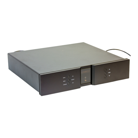
External appearance of TDA-500 is shown at Figure 1.
Figure 1 – External appearance of TDA-500
TDA-500 can be used in metal, chemical, mining, wood-processing, gas and oil
industries, including rescue services, transport facilities etc.
The TDA-500 is installed in telecommunications cabinets or racks located in hardware,
control rooms, or offices.

TDA-500 DIGITAL POWER AMPLIFIER
User Manual
armtel.com page 5/28
info@armtel.com © Armtel
ENG
1.2 Main specifications
Main specifications for TDA-500 are given in Table 1.
Table 1 – Main specifications of TDA-500
Name of parameters Measuring conditions
Value
Two-channel
mode
Single-channel
mode
The nominal value of the output
power, W
40 Ohm/100 V
230 V AC
2х250 -
200 Ohm/100 V
230 V AC
- 1х500
Output power, W
48 V DC
2х240
1х480
The coefficient of nonlinear
distortions + noise, %
1 kHz 200 W
0,29
Frequency range, Hz
-3 dB
90 - 20000
Input sensitivity, V eff
70 Hz - 20 kHz
1
Input impedance, kOhm
1 kHz
10
Signal–to-noise ratio, dB
1 kHz, 250 W; loudness 0,5
85
Electronically balanced inputs
One input per each channel;
If necessary, you can connect both inputs
Current consumption, A
Standby 48 V DC
0,1
0,1
Standby 230 V AC
0,058
0,058
Without signal 48 V DC
0,25
0,25
Without signal 230 V AC
0,14
0,14
Full load 48 V DC sine
signal
12,5 12,5
Full load 48 V DC sine
signal 100 V, 40 Ohm
3,1 3,1
Power loss 100 % full load, W
-
320
Power loss 500 % full load, W
-
171
Power loss in standby mode, W
-
12

TDA-500 DIGITAL POWER AMPLIFIER
User Manual
page 6/28 armtel.com
ENG
Table 1 – Main specifications of TDA-500 (end)
Name of parameters Measuring conditions
Value
Two-channel
mode
Single-channel
mode
Design parameter
Dimensions, mm
-
19ʺ2HE (482x88x256)
Weight, kg
16,5

TDA-500 DIGITAL POWER AMPLIFIER
User Manual
armtel.com page 7/28
info@armtel.com © Armtel
ENG
1.3 Operations conditions
TDA-500 operations conditions: ambient operating temperature range from
minus 5 °C to plus 40 °C, ambient atmospheric pressure from 84,0 to 106,7 kPa (from 630 to
800 mmHg).
TDA-500 withstands without mechanical damage exposed to sinusoidal vibration
25 Hz frequency with peak acceleration amplitude up 19,6 m/s2.
TDA-500 in packed form withstands without mechanical damage the effect of
mechanical impacts of multiple action with peak acceleration up to 147 m/s2with a total
number of up to 15000 impacts.
TDA-500 is meet the requirements of Technical regulations of the Customs Union
TR CU 004/2011 «On safety of low-voltage equipment», provides safety for service personnel
and meets the electrical safety requirements set out in GOST IEC 60065-2013.
TDA-500 is meet the requirements of Technical regulations of the Customs Union
TR CU 020/2011 «Electromagnetic compatibility of technical means» and meets the
requirements of electromagnetic compatibility set out in GOST 32136-2013 and
GOST EN 55103-1-2013.

TDA-500 DIGITAL POWER AMPLIFIER
User Manual
page 8/28 armtel.com
ENG
1.4 Scope of supply
The scope of supply for TDA-500 is provided in Table 3.
Table 3 – Scope of supply
Identification Name
Quantity,
pcs.
Note
ARMT.665230.139
TDA-500 Digital Power Amplifier
1
Power connector «48 V DC» 1
Response connector for
the connector «DC IN»
Output connector «OUT» 2
Response connector for
the connector «OUT A»
/ «OUT B»
Input connector «Channel» 2
Response connector for
the terminal block
«Chennel A» /
«Chennel B»
Power supply cable
1
Packaging
Package 1
Operational documentation
ARMT.665230.139PP
Product Passport
1
ARMT.665230.139UM
User Manual
1

TDA-500 DIGITAL POWER AMPLIFIER
User Manual
armtel.com page 9/28
info@armtel.com © Armtel
ENG
1.5 Design
The TDA-500 is installed in standardized 19 "racks in accordance with DIN 41494.
The TDA-500 has two independent amplification channels with a power of 250 W each
(when operating in two-channel mode) or one independent amplifying channel with a power
of 500 W (when operating in a single-channel mode).
The TDA-500 is powered from a 230 V AC power supply. Additionally, it is possible to
connect a backup power supply in the form of a 48 V DC power supply. In the event of a
power failure, the TDA-500 automatically switches to a backup power supply.
The TDA-500 design provides:
–availability of controls and indication TDA-500. TDA-500 control and indication
bodies are located on the front panel;
–availability of protection against overvoltage, short circuit, no-load and
overheating;
–availability of mounting holes for installation in a 19 "rack;
–convenient access to the elements involved in the operation;
–the presence of potentiometers to adjust the volume of sound, high and low
frequencies for each channel;
–presence on the front panel of the TDA-500 case with LED indication for each
channel.
Front panel view of ТDA-500 is illustrated at Figure 2.
1 – indicator «BATTERY»; 2 – indicator «MAINS»; 3 – indicator «FAULT»;
4 – indicator «OK»; 5 – indicator «CLIP»; 6 – potentiometer «BASS»;
7 – potentiometer «TREBLE»; 8 – potentiometer «VOLUME»;
9 – indicator «SIGNAL»
Figure 2 – Front panel view of ТDA-500

TDA-500 DIGITAL POWER AMPLIFIER
User Manual
page 10/28 armtel.com
ENG
The front panel of the TDA-500 contains:
1 –indicator «BATTERY» (red) – indication of operation mode from a 48 V DC power
source or battery operation;
2 – indicator «MAINS» (green) – indication of the mode of operation from the
alternating current with a voltage of 230 V;
3 – indicator «FAULT» (red) – indication of faults in the amplifier operation: overheating,
short circuit on the line or exceeding the permissible load of Channel A;
4 –indicator «OK» (green) – indication of work in the active mode of Channel A;
5 – indicator «CLIP» (red) – indication of Сhannel A overload;
6 – potentiometer «BASS» – adjustment of low frequencies of Channel A;
7 – potentiometer «TREBLE» – adjustment of high frequencies of Channel A;
8 – potentiometer «VOLUME» – volume control of Channel A;
9 – indicator «SIGNAL» (yellow) – indication of the input signal on Channel A.
For Channel B, the front panel has similar indicators and potentiometers.
The rear panel view of TDA-500 is illustrated at Figure 3.
1 – connector «AC IN»; 2 – connector «DC IN»; 3 – connector «OUT B»; 4 – connector «OUT A»;
5 – terminal block «Channel А»; 6 – terminal block «Channel В»;
7 – marking of contacts of terminal blocks «Channel А» and «Channel В»
Figure 3 – The rear panel view of TDA-500
The rear panel contains:
1 – connector «AC IN» – AC power plug for connecting the power cable. In the
connector housing there is a fuse 6 A, designed to protect the circuits of the electric network
from short-circuit currents in case of failure TDA-500;
2 – connector «DC IN» – two-pin plug, input 48 V DC;
3 – connector «OUT B» – three-pin plug, output Сhannel B;

TDA-500 DIGITAL POWER AMPLIFIER
User Manual
armtel.com page 11/28
info@armtel.com © Armtel
ENG
4 – connector «OUT A» – three-pin plug, output Сhannel A;
5 – terminal block «Channel A» – inputs of signal and special signals for controlling the
amplifier of Сhannel A;
6 – terminal block «Channel B» – inputs of signal and special signals for controlling the
amplifier of Сhannel B;
7 – marking of contacts of terminal blocks «Channel A» and «Channel B».
A power cable is connected to the connector «AC IN», which is designed to connect
the TDA-500 to the power supply.
The delivery set includes terminal connectors "48V DC", "OUT" and a terminal block
"Channel" intended for connecting external devices to the TDA-500. The pin assignment of
connectors is detailed in Appendix A.

TDA-500 DIGITAL POWER AMPLIFIER
User Manual
page 12/28 armtel.com
ENG
1.6 Marking
On the top cover of the TDA-500 a bilingual nameplate (in the Russian and English
languages) is fixed in accordance with Figure 4, containing the following data:
−name and trademark of the manufacturer;
−product name;
−sign of product circulation on the market of the CU member states;
−permissible operating temperature range;
−special waste disposal mark;
−product serial number;
−date of manufacture;
−mark «Made in Germany».
The serial number is unique for each product.
Figure 4 – Nameplate

TDA-500 DIGITAL POWER AMPLIFIER
User Manual
armtel.com page 13/28
info@armtel.com © Armtel
ENG
1.7 Package
The TDA-500 with the documents, which come with the supply package, is packed in
consumer package (cardboard box).
A label in Russian language and English language is glued onto the consumer package,
said label containing the following inscriptions and symbols:
–product name and description;
–name, trademark and reference information of the manufacturer;
–commercialization mark for products on the market of Customs Union member
states;
–serial number and date of manufacture;
–handling symbols according to GOST 14192-96 and TR CU 005/2011.
The package is made according to the drawings of the product manufacturer and
enables storage of the TDA-500, provided requirements set in Section 5 are met.
For shipment of the TDA-500 from the manufacturer, consumer package contents are
placed in the package place, which ensures protection from mechanical damage, direct
ingress of atmospheric precipitation, dust and solar radiation during transportation

TDA-500 DIGITAL POWER AMPLIFIER
User Manual
page 14/28 armtel.com
ENG
2 INTENDED USE
2.1 Operating limits
2.1.1 The TDA-500 shall be used under exposure factors and ambient parameters which
do not exceed permissible values given in 1.3.
2.1.2 Do not use the product in rooms with high humidity (more than 80 %) or
conductive dust.
2.1.3 The requirements for operating conditions and the choice of the place of
installation given in this document take into account the most typical factors that affect the
operation of TDA-500.
Factors that cannot be predicted, estimated or verified, and which the manufacturer
was unable to factor in during development may exist or arise during operation at the
operating facility.
2.2 Preparation for use
2.2.1 Preparation of TDA-500 for use is carried out by representatives of the
manufacturer, or by personnel trained (instructed) in the operation of Armtel LLC products.
The main preparation of the product for use is carried out during installation and connection.
2.2.2 Preparing the TDA-500 for work includes a number of activities:
–remove the TDA-500 from the shipping container and / or consumer packaging;
–check the completeness of the TDA-500 in accordance with the attached
passport;
–conduct an external examination of the product for damage (cracks, dents,
chips, etc.). In the process of external inspection, it is necessary to pay attention
to the integrity of the product and the condition of the connection connector.
ATTENTION: IT IS NOT ALLOWED TO USE THE PRODUCT WITH THROUGH CASE
DAMAGE AND / OR DAMAGE TO THE CONNECTOR!
2.2.3 Install and connect the TDA-500 at the place of operation (see 2.4).

TDA-500 DIGITAL POWER AMPLIFIER
User Manual
armtel.com page 15/28
info@armtel.com © Armtel
ENG
2.3 Safety precautions
2.3.1 For operation of TDA-500 are allowed personnel who have been instructed
undergone appropriate training and become familiar with the requirements of this User
Manual.
2.3.2 When using the TDA-500 for its intended purpose, it is necessary to comply with
the safety requirements determined by the "Labor Protection Rules for the Operation of
Electrical Installations" when working with electrical receivers with voltages up to 1000 V.
2.3.3 To avoid electric shock, do not:
−turn on the product with a damaged power and communication cables;
−connect and disconnect communication cables only when the power cable is
disconnected.
ATTENTION: DISASSEMBLY OF ARTICLE CONNECTED TO POWER SUPPLY IS
PROHIBITED!
In order to ensure fire safety, follow the following rules:
−before connecting the product to the power supply, make sure the power cable
are properly insulated;
−protect power and communication cables from damage.
2.4 Installation, connection and dismantling
2.4.1 Install the TDA-500 at the place of operation in a 19 "cabinet (rack).
Note – The set of fasteners for installation TDA-500 in a 19" cabinet (rack) is not included in
the scope of supply and is selected by the user independently.
2.4.2 Install the connectors supplied in the delivery set in accordance with Appendix A
in the following order:
−install the connector «48V DC» on the cable coming from the auxiliary power
supply;
−install the connectors «OUT» on the cables of the output lines (loudspeakers);
−install the connectors «Channel» on the cables coming from the signal sources.
2.4.3 Figures 5 and 6 show a variants of the TDA-500 amplifier connection diagram.

TDA-500 DIGITAL POWER AMPLIFIER
User Manual
page 16/28 armtel.com
ENG
Figure 5 – Connecting TDA-500 to module ACM-IP2 in single-channel mode
Figure 6 – Connecting TDA-500 to module ACM-IP2 in two-channel mode
2.4.4 Connect the TDA-500 on the place of operation in accordance with Figures 4
or 5 in the following order:
−connect the connectors «OUT» of output lines cables (loudspeakers) to the
connectors «OUT A» and «OUT B» of the TDA-500;
−connect the “Channel” connectors of the cable coming from the signal sources
to the connectors «Channel A» and «Channel B»;
−connect the power cable connector from the supply of supply to the connector
«AC IN» TDA-500;

TDA-500 DIGITAL POWER AMPLIFIER
User Manual
armtel.com page 17/28
info@armtel.com © Armtel
ENG
−set the potentiometers "VOLUME" to the extreme left position corresponding to
the minimum volume level;
−connect the TDA-500 with the power cable to the 230 V AC power supply
through the socket containing the safety earthing terminal.
Note – In the event of a power failure from the 230 V power supply, the TDA-500 will
automatically switch to backup power supply.
2.4.5 TDA-500 is dismantling in the following order:
−disconnect power supply of TDA-500 and communication cables;
−dismantle TDA-500 from the cabinet (rack);
−pack the TDA-500 in consumer packaging.
2.5 Operation
2.5.1 Activity description
2.5.1.1 TDA-500 is intended for amplifying audio frequency signals and transmitting
them over a two-wire communication line, for working with acoustic systems in sound
amplification and notification complexes. TDA-500 is designed to amplify the power of low-
frequency signals in DCN and IPN systems manufactured by Armtel LLC and is connected to
them via ACM-IP or ACM-IP2.
2.5.1.2 TDA-500 generates output signals of 50 or 100 V.
2.5.1.3 TDA-500 is designed for continuous 24-hour a day operations.
2.5.1.4 The TDA-500 is powered from a 230 V AC power supply. Additionally, it is
possible to connect a backup power supply in the form of a 48 V DC power supply. In the
event of a power failure, the TDA-500 automatically switches to a backup power supply.
2.5.1.5 Each channel of the TDA-500 provides balanced line inputs for connecting audio
sources and balanced line outputs for cascading multiple amplifiers.
2.5.1.6 The TDA-500 operating modes are displayed on the front panel with LED
indication. Volume, treble and bass are controlled by potentiometers using a slotted
screwdriver with an insulated handle.
2.5.2 General requirements
2.5.2.1 For operation of TDA-500 are allowed personnel who have been instructed and
become familiar with the requirements of this User Manual.

TDA-500 DIGITAL POWER AMPLIFIER
User Manual
page 18/28 armtel.com
ENG
2.5.2.2 Before operation of TDA-500:
−check for damage of TDA-500;
−using a screwdriver, set the potentiometers «BASS», «TREBLE» and «VOLUME»
to the extreme left position corresponding to the minimum level;
−make sure the TDA-500 is connected to the mains and to an auxiliary 48 V DC
power supply;
−make sure indication «MAINS» is present when the TDA-500 is connected to a
230 V, 50 Hz power supply network, or indication «BATTERY» is present when
the TDA-500 is connected to a 48 V DC power supply.
Note - In the event of a 230 V power failure, the TDA-500 will automatically switch to
backup power from a 48 V DC power supply.
−make sure that there is no indication «FAULT».
2.5.3 Using TDA-500
2.5.3.1 Connect TDA-500 in accordance with 2.4.4.
2.5.3.2 Make sure that there is an indication «SIGNAL» on Channel A and Channel B.
2.5.3.3 Make sure there is an indication «OK» on Channel A and Channel B.
2.5.3.4 Turning the potentiometers «BASS» with a screwdriver, adjust the level of low
frequencies of Channel A and Channel B.
2.5.3.5 Turning the potentiometers «TREBLE» with a screwdriver, adjust the high
frequency levels of Channel A and Channel B.
2.5.3.6 Turning the potentiometers «VOLUME» with a screwdriver, set the sound
volume, thus adjusting the output signal level on the speaker connected to the terminal
block «Channel A».
2.5.3.7 Make sure that there is no continuous activation of the indication «CLIP».
Note –Only short-term activation of the indication «CLIP» is allowed at peak values of
the signal level.
This manual suits for next models
1
Table of contents
