User manual AMI –120/AMI –240 page 10
12. Advanced Functions
12.1 Noise Gate
A Noise Gate circuit has been inserted in order to minimize the background noise on the output when no signal is
applied at the input. The channel opening threshold could be adjusted through the controls (14) located on the front
panel of the equipment. Internally bypassable by jumper.
12.2 Pre Out Setting
Internal jumpers are provided to assign Pre or Post Master
Pre Out setting. Thanks this internal setting it is possible
to adjust the Pre Out level by the Master control or make it
independent, following the system requirements.
From the factory, Pre Master setting is assigned.
The figure shows the instructions to assign the Pre Out Setting.
13. System Setup
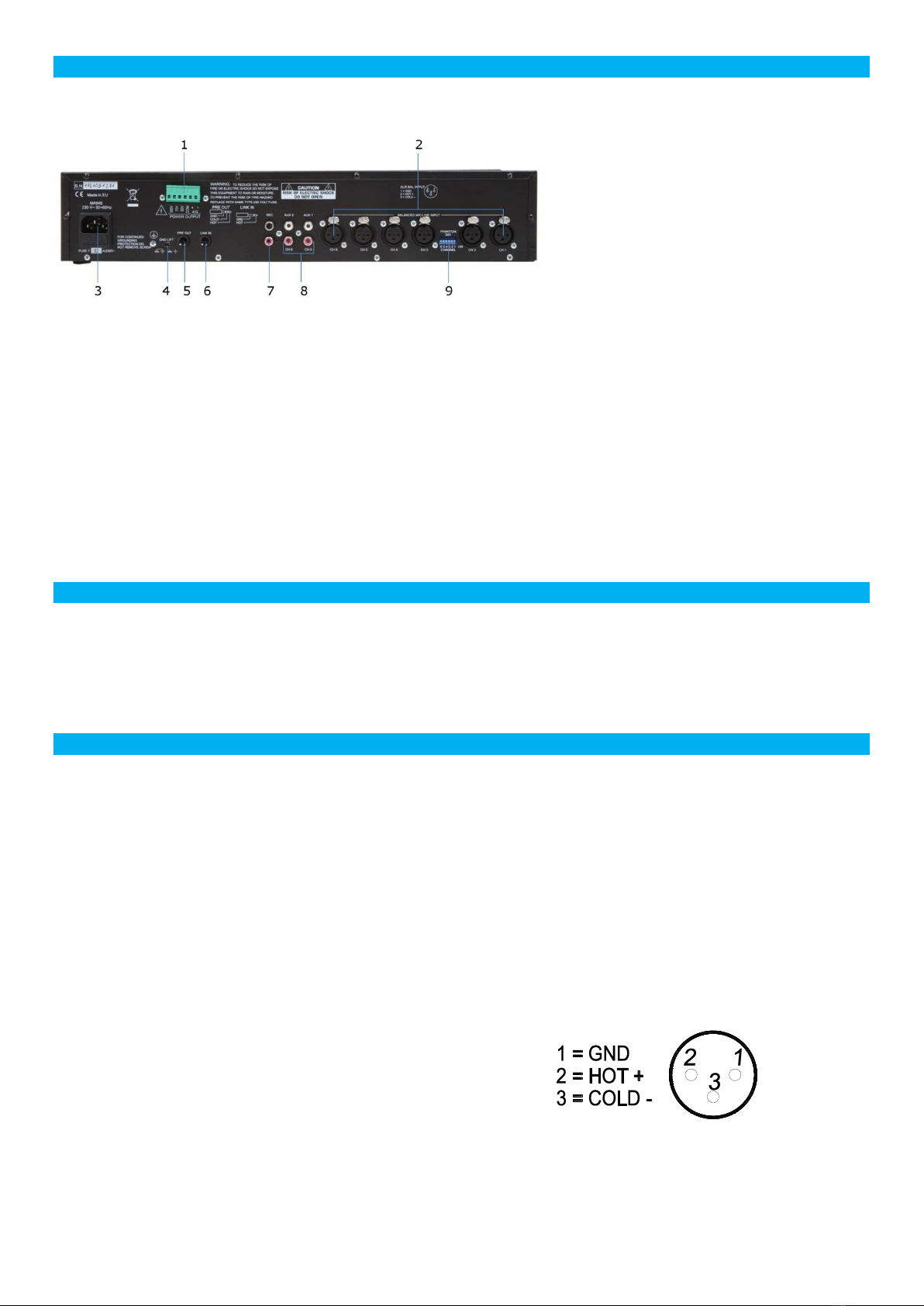
The inputs of the mixer can accommodate a wide range of sources including active paging stations, dynAMI seriesc
microphones, DVD,CD and Mp3 players and mixers.
The Preout outputs may be used to drive power amplifiers, mixers, or mixer amplifiers.
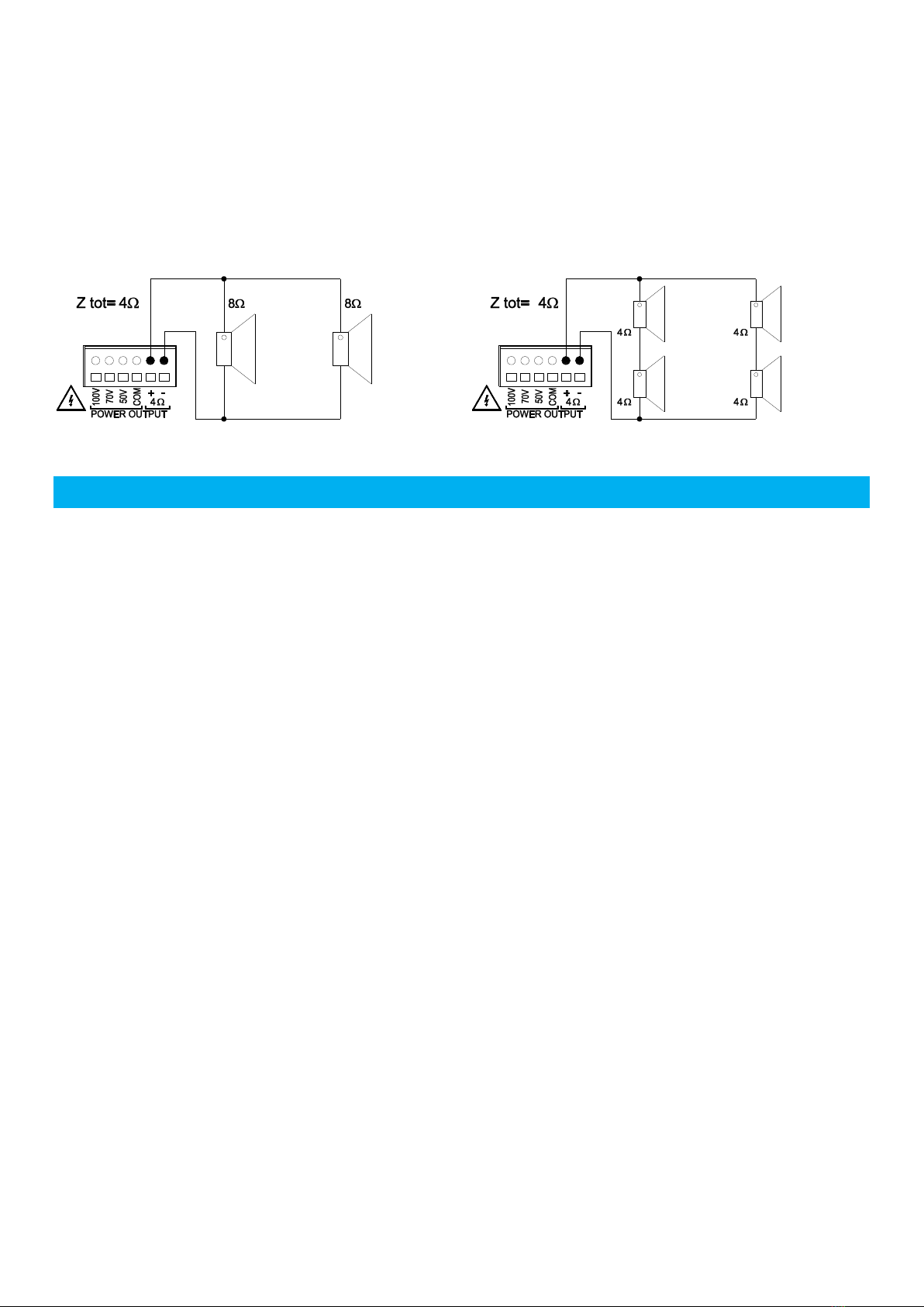
The Power output may be used to drive constant voltage or constant impedance speaker lines.
Each installation will require setting the appropriate relative mix of levels between paging,
program sources and mic/line inputs for each line or amplified outputs.
Because of the variation in levels between the possible sources, the mixer offers a number of gain stage adjustments
and parameter tools so you can set the correct levels for your application.
Setting up correct parameter structure through the whole system is important to achieve optimal results.
The following step by step procedure has been devised to assist during the setup process.
Connect the speaker lines to the correct power output socket.
Active the phantom supply by the dipswitch (9) located on the back panel if electrect microphones are used.
Ensure that all the Gains and Volume controls are at minimum, and that the Tone controls are flat.
Keep the master volume for each output channel at about 10%÷20%
Keep the input channels LEVEL (9) at about 5 (50%).
Adjust each input channel GAIN (2) in order that the Level Meter (10) green led lit continuously also with low input
signal and that the +3dB red led lit with strong input signal.
Adjust GATE (11) in order to avoid the noise gate activation cause background noise or undesired signal but by
the speaker voice or input signal only.
Adjust the master volume and the input channels LEVEL in order to obtain the required sound pressure.
Adjust the 3 band equalizer (1,3,4) for each channel in order to obtain the best result with each different input
source.