Dateq MusicAll DA-120 User manual

1 11 /
CLASS-D
1, 2 or 4 CHANNEL AMPLIFIER
DA-120 DA- 122 0 DA- 124 0
DA-24 0 DA- 24 2 0 DA- 24 4 0
DA-50 0 DA- 50 2 0 DA- 50 4 0
INSTALLATION AND O N MANUAL PERATIO

2
1. Rea d these instructions.
2. K e e p these instructions.
3. He ll warnings. ed a
4. F lo all instructions. ol w
5. Do not use th near water. is device
6. Clean only w t cloth. i h dry
7. Do not block any v ila i n openings. Install in a ccordance with th m nufacturer’s instructions. ent t o e a
8. D t t e he t ou s ad or h r c ud go no ins all n ar any a s rces uch as r iat s, eat egisters, stoves, or other (in l in amplifiers) that produce devices
he t.a
9. WARNI : To reduce the risk of fire or electric sho o not expose this apparatus to rain or .NG ck, d moisture
10. Connect the device to a mains outlet with a protective ar connection. e th
Important nformation Safety I
3
WARNING!
TO PR GEVENT FIRE OR SHOCK HAZARD, DO NOT USE THE PLU WITH
AN N ION CORD, RECEPTACLE OR OTHER OUTLET UNLES S THE DES EXTE S BLA
CAN BE FULLY INSERTED EVENT BLADE EXPOSURE. TO PR
TO REDUCE T E K OF FIRE OR ELECTRIC SHOCK, DO NO T EXPOH RIS SE
THIS APPLIANCE TO RAIN OR MOISTURE.
TO PREVENT ELECTRICAL SHOCK
MAT .CH WIDE BLADE PLUG TO WIDE SLOT, FULLY INSERT
Saf t rning e y Wa

4
Introduction
- -- -------------------------------------------- -- ------------------------------------------ -- ------------------- -- -- ------- -- --- ----- --- ----- ----------------------------------------------------------------------------------------------------------- - -
1
Impor t Safety Information 2tan ----------------------- ------------------------------------------------- --------------------- ------------------------------------------ --
Safety Warni ng 3
------------------------------------ ---------------------------------- ----------------- -------------------------------------- --------------------------------
Conte s 4 nt ------------------------------------------- ---------------------------------------------- ----- ---------------------------------- --------------------------------------- -
Introd i n 5 uct o ------------------------------------------------------------------------ --------------------------------- ------------------ ---------------------------------------
Front Pane 6 l -------------------------------------------------------------------------- --------------------------------------------------- ------- --------------------------------
Rear P el 7 an --------------------------------------------------------------------------- --------------------------------------------------- --------- ------------------------------
Spe Connection 8 aker --------------------------------- ---------------------------------------- ----------- --------------------------------------------------------------------
Block Diagr 9 am-------------------------------------- --------------------------------------------- ------ -----------------------------------------------------------------------
Speci i i n 10 f cat o -------------------------------------- --------------------------------------------------- -------------------- ----------------------------------------------------
Contents

5
Features:
Switching power technology po e plifier w r am
Clas ti ns-D PA power amplifier of minimum power consump o
Less rack space and less h eneration eat g
Single channel power amplif e ” rack , double and quadruple 1HE housingi r in 19
Rated power output at 120W, 2 500W 4 or0W
Separat pea er outputs 8 /100V e s k Ω
Balanced XLR input by phoenix connector
Each input w t eparate gain control. i h s
Each channe w high-cut filter l ith
Buil -t in auto standby feature energy saving
Separat hannel indicators for protection, clip, put a put e c nd outin
Complete short circ overload, high temp, clip nd DC protect onuit, i a
Wide AC input from to 2 0V input 110V 4
Description:
Th D r e class-D power amplifier s i ching power e A ang w trange uses
te hn o ti n ac ol gy, which minimum power consump o nd results in
much hi er efficiency up to 85%, it helps a e gh to s v and
installat on a ace, generate less heat so as o ex nd its i r ck sp tet
per of rmance life span as a result.
The class-D amplifiers rated power utput 0W, 12 have a o of
2 0W ub4 or 500W, so it could be used as digital p lic address
syst m ute at minimum cost. The versatile loudspeaker puts of both o
high impedance & low impedance 8 ohms 100V . It can be used in
P n a l ti obA fixed i st llation Hi-fi stereo sound instal a on j s. or
Th r e e is one balanced input by phoenix connector each channel for
w ti h gain control. individual
The bu lt- n i h-pass filters c be enabled i i h g and auto-standby an
(or disabled through the dip switch pre-setting. )
Au al tomatic standby input for one is activated when there is no sign
minute, wake up at sight of any input. Visual workand s ing
status indica include protection, clip, input nd output r easy tors fo a
supervis o ith complete short circuit, overload, h gh te , clip i n. W i mp
and DC prot c n e tio .
Wide AC po e uppl from 1 V to 2 0V, thus t pport w r s y i su10 4 s
world ide s und system installation.w o
In o troducti n
6
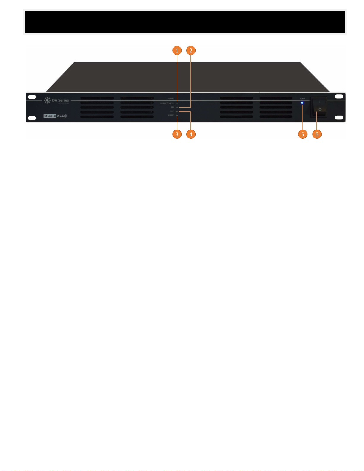
1. PROT
Protection indicator will ght on in orange once he amplifier protection status. The ection ma result speaker li t is in prot y be of a
li ne short circuit, speaker line open circuit, overload and inner working temperature amplifier too high, this ind c o give visual i at r s
guidance k for repair There are protect on indicators for each , . separate channel.as i
WHEN THE AMP IS IN STANDBY MODE, PROTECTION LED WILL TURN ON. When audio signal is back the amplifier will turn on again.
2. C IPL
Cli nd or o indp i icator will light in red once the input utput is too high. There are separate CLIP icators for each channel.
3. I T NPU
Input c tor will light in green once there s input signal detected. There sepa te input indicators for e channel. indi a rai are very
4. O UT U PT
O p t is arut u indicator will light in green once there output signal There are ate output indicators for each channell. sep .
5. PO WER
P e in icator will be light in blue once the n t h been powered by AC or DC . ow r d i as u 24V
6. PO SWITCH WER
P e witch used to power on and power off ow r s .the device
Front Panel

7
1. AC P OWER CORD
AC power cord for input from 1 0V to 2 0V, 0 4 auto-switching power supply.
2. LI PUT NE IN
The line input supp both balanced or inputs from audio s u ces or mixer, these phoe i connectors. ort o r n x s unbalanced inputs are equipped with
3. GAIN CONTROL
The ga n control is used to adjust various inputsi from the input .
4. 24 DV C Input
The 24V DC input is used to con c with battery fo r backup power supply in s AC fails. ne t ca e of
5. 100V SP K OUTPUT EA ER
The speaker ou ts shall be connected to 100V line loudspeak the negative end to the speaker tive end and e positive end tpu ers, thnega
to se d the speaker positive end. There are parate 100V speaker outputs which could be respectively. These speaker manage
output are phoenix connector . s equipped with s
Never mix the negative end a e positive one, which may cause the short circui rotection. nd th t p
Never connect low impedance loudspeaker to he 100V . a t connection
6. 8 SPEAKER OUTPUT Ω
Use the 8 Ω and COM connections when using impedance Ω COM connection low 8 loudspeakers, the negative end to and the
positive end to the . 8 Ω connection Th s tor .e e speaker output are phoenix connec s equipped with s
Never mix the negative end a e positive one, which may cause the short circui rotection. nd th t p
Never con e 100V loudspeaker to these n ct a 8Ω connections.
7. HIGH PASS ER FILT
The high pass filter function w l be enabled or sabled by . There il di setting the HPF dipswitch are hig ss filters .h pa for every channel
8. AUTO-STANDBY
The Auto sta function will be enabled he enabled auto-standby function ndby or disabled by setting the Standby dipswitch. T
will automatically standby no input has been detected with minute. set the amp in when 1 The protect LED will light up. in
The fier will imm di el wake up there is detection of input signal. There are separate auto-standby dipswitchampli when es for e at y
Rear l Pane
every channel.

8
Before conne ting speakers, disconnect the AC power cab Note the proper connecting terminals as sho wn belo Make sure that the total c le. w.
impeda e is not less than the rated impedance indi catnc ed.
- Connecting 4-16 Sp Systems Ω eaker
When conn ting conventional 4-16 speaker systems, con the speaker’s positive (+) side to the ter minal l beled . Connect the ec nect aΩ 8Ω
speak negative (-) side to the terminal labeled C M. er’s O
- Connecting Distributed S er ms 100V Syste peak
When connecting a -impedance (100V) speaker in parallel, con c the speaker’s positive (+) side to the term l labeled 100V . high system +ne t ina
Conne he speaker’s negative (-) side to the term inal labe . ct t led 100V -
FOR 4 LOW IMPEDANCE SPEAKER CONNECTION FOR 8 LOW IMPEDANCE SPEAKER CONNECTIONΩ Ω
FOR 100V SPEAKER WITH TR O MER CONNECTIONANSF R WRONG SPEAKER CONNECTION
Speaker Con nection
9
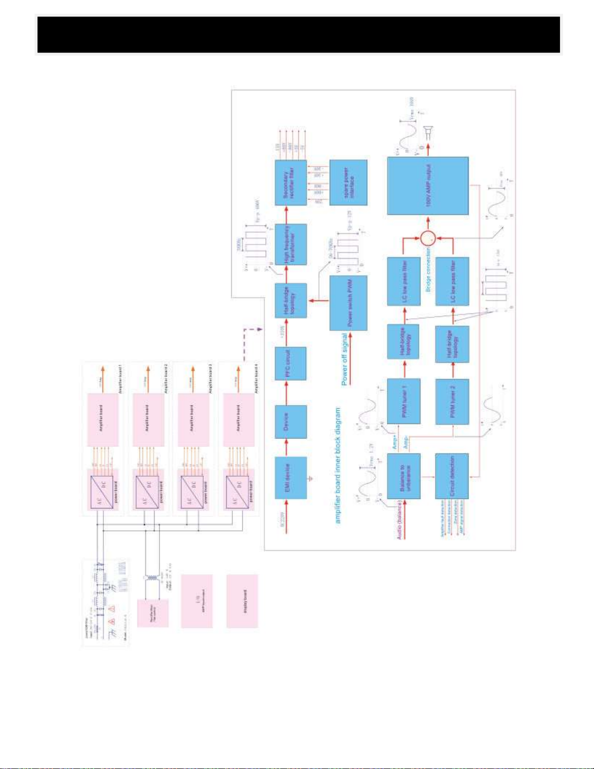
Bloc m k Diagra

10
Spe Output aker 8 & 100V Ω
Frequency Response HPF OFF 20Hz-2 (+1/-2dB) 0KHz
HPF 2 ON 70Hz- 0KH +1/-3dB) z (
I pun t 0.775V, 0dBu, balanced phoenix conn ector
I pu In t mpedance 10KΩ
THD <0.1% (1KHz/-3dBv W) , 100
S/N R atio > B 80d
C osr stalk >60dB, 1KH ax output z, M
Pow r S ply e up Wi -60Hzde AC input from 110V & 2 0V, 50 4
Di nsi n me o 482(W)x420(D)x44(H) mm
Warranty 3 years warranty and free spare parts
Spec o s ificati n
Model 20 DA-240 DA-500 DA-1
Model 20 DA- 240 DA- 12 2
DA- 500 2
Model 20 DA- 240 DA- 500 DA- 14 4 4
Description
Description
Description
Single Channel Clas D o Amplifiers- P wer
Dual Channel Clas D o Amplifiers- P wer
Quadruple Channel Clas D o Amplifiers- P wer
Rated Output Power
Weight (Kg)
Weight (Kg)
Weight (Kg)
Rated Output Power
Rated Output Power
1x W 1x 1x120 240W 500W
4.0 4.2 5.0
6.5 7.5 8.5
8.3 8.8 9.8
2x500W
4x W 4x 4x120 240W 500W
2x240W 2x120W

11

12
This manual suits for next models
8
Table of contents
Other Dateq Amplifier manuals


