ARMTEL DWEx-IP2 Series User manual
Explosion-proof Call Station
DWEx-IP2
RMLT.465311.007UM
User Manual
Версия 5
26.30.11.190
2020
Document version 7
26.30.11.190
2020
ENG

armtel.com
© Armtel info@armtel.com

EXPLOSION-PROOF CALL STATION DWEX-IP2
User Manual
armtel.com page 1/60
info@armtel.com © Armtel
ENG
INTRODUCTION
This User Manual applies to various versions of the Explosion-proof Call Station
DWEx-IP2 RMLT.465311.007 manufactured by Armtel LLC, and is intended to familiarize
the User with the device and the procedure for its operation at the installation site.
Explosion-proof Call Station DWEx-IP2 is designed for use in distributed loudspeaking
operational communication and paging systems, in communication systems equipped with
the RMLT.465275.012 ARMTELICS Hardware and Software Package and IPN systems
(manufactured by Armtel LLC, Russia)
Short name of product – DWEx-IP2.
DWEx-IP2 is designed for employment in an explosion proof zones of the premises
and external installations in accordance with certain explosion proof marking, requirements
Technical Regulation of the Customs Union "On safety of equipment intended for use in
explosive atmospheres" (TR CU 012/2011), GOST IEC 60079-14-2013, chapter 7.3
«Regulations for Electrical Installation» (PUE), ATEX 2014/34/EU and other normative
documents, regulating usage of electrical equipment in highly explosive zone.
DWEx-IP2 has explosion-proof categories «explosion-proof equipment»», provides
protection type of «flameproof enclosure (d)» according GOST IEC 60079-1-2011 and
EN 60079-1:2014, provides protection «increased safety (е)» according GOST R IEC 60079-
7-2012 and EN 60079-7:2015, provides protection «intrinsically-safe circuit «i» type «ib»
according GOST 31610.11-2014 (IEC 60079-11:2011) and EN 60079-11:2012, provides
protection type of «dust ignition protection type «tD» according GOST R IEC 60079-31-
2010 and EN 60079-31:2014, designed according GOST 31610.0-2014 (IEC 60079-0:2011)
and EN 60079-0:2012.
Note – Normative documents whose name begins with the letter combination EN are
related to the ATEX Directive 2014/34 / EU.
Explosion-proof marking as per GOST 31610.0-2014 (IEC 60079-0:2011):
«1Ex d e ib IIC T4 Gb» and «Ex tb IIIC T 135°C Db».
Explosion-proof marking as per EN 60079-0:2012:
«II 2 G Ex db eb Ib IIC T4 Gb» and «II 2 D Ex tb IIIC T135°C Db IP66».
Maintenance personnel for the DWEx-IP2 shall be appointed by the management at
the installation site.
The maintenance personnel shall be required to know the operating procedure of
the DWEx-IP2 to the extent provided for by the User Manual.

EXPLOSION-PROOF CALL STATION DWEX-IP2
User Manual
page 2/60 armtel.com
ENG
Duties of the maintenance personnel shall include maintenance of the DWEx-IP2 in
accordance with this User Manual.
ATTENTION! In connection with systematic work to improve the design and
manufacturing technology, it is possible some discrepancy between the description and
the supplied product, which does not affect its operation or maintenance.

EXPLOSION-PROOF CALL STATION DWEX-IP2
User Manual
armtel.com page 3/60
info@armtel.com © Armtel
ENG
SAFETY PROVISIONS
During installation and operation of DWEx-IP2, observe safety precautions laid out in
local regulations on electrical safety.
Never operate the product with a damaged power, communication or earthing
cables.
To avoid electric shock, do not:
−turning on the device with damaged power, interface or earthing cables;
−the interface cable can be connected and disconnected if the power cable is
disconnected.
The sign “X”, which placed after marking and ATEX certificate number, is indicates
that this equipment of protection system is subject to special conditions for save use:
−ambient temperature from -40 °Сto +55 °С.
WARNING: DO NOT OPEN WHEN ENERGIZED
ATTENTION! NEVER DISMANTLE THE PRODUCT CONNECTED TO MAINS
In order to ensure fire safety, follow the following rules:
−before connecting the product to the power supply, make sure the power and
communication cables are properly insulated;
−protect power and communication cables from damage.
The safety provisions for specific operations described in this manual are marked
with:

EXPLOSION-PROOF CALL STATION DWEX-IP2
User Manual
page 4/60 armtel.com
ENG
CONTENTS
INTRODUCTION.................................................................................................................................................................... 1
SAFETY PROVISIONS........................................................................................................................................................... 3
CONTENTS .............................................................................................................................................................................. 4
1 DESCRIPTION AND OPERATION................................................................................................................................. 6
1.1 Basic parameters and characteristics (properties) ...................................................................................... 6
1.1.1 Features ............................................................................................................................................................. 6
1.1.2 Specifications (properties) ........................................................................................................................14
1.1.3 Operations conditions................................................................................................................................16
1.1.4 Structure and operation ............................................................................................................................17
1.1.5 DWEx-IP2 design..........................................................................................................................................19
1.1.6 Scope of supply ............................................................................................................................................25
1.1.7 Labeling ...........................................................................................................................................................26
1.1.8 Package............................................................................................................................................................27
1.1.9 Explosion protection...................................................................................................................................28
1.2 Description and operation of product components................................................................................30
1.2.1 General information....................................................................................................................................30
1.2.2 Integrated amplifiers ..................................................................................................................................30
1.2.3 ADSL module.................................................................................................................................................31
1.2.4 Dial pad (keypad module) ........................................................................................................................31
1.2.5 Pushbuttons (direct call buttons)...........................................................................................................31
1.2.6 Handset............................................................................................................................................................32
1.2.7 Intrinsic protection boards .......................................................................................................................32
1.2.8 Electrical mechanical relay........................................................................................................................32
1.2.9 DW-MB01-IP2 main board.......................................................................................................................33
1.2.10 DART-6UL processor module ...............................................................................................................33
1.2.11 DW-BC board..............................................................................................................................................34
2 INTENDED USE ................................................................................................................................................................35
2.1 Operating limits .....................................................................................................................................................35
2.2 Ensuring explosion protection during operation ......................................................................................36
2.3 Safety precautions.................................................................................................................................................36
2.4 Preparation for use ...............................................................................................................................................37
2.5 Installation, connection and dismantling .....................................................................................................38
2.5.1 Ensuring explosion protection during mounting.............................................................................38

EXPLOSION-PROOF CALL STATION DWEX-IP2
User Manual
armtel.com page 5/60
info@armtel.com © Armtel
ENG
2.5.2 Installation ......................................................................................................................................................40
2.5.3 Connection .....................................................................................................................................................42
2.5.4 Dismantling ....................................................................................................................................................43
2.6 Operation .................................................................................................................................................................44
2.6.1 Configuration.................................................................................................................................................44
2.6.2 Product operating modes.........................................................................................................................44
2.6.3 Troubleshooting...........................................................................................................................................46
3 MAINTENANCE................................................................................................................................................................47
3.1 General guidelines ................................................................................................................................................47
3.2 Safety precautions.................................................................................................................................................47
3.3 Maintenance procedure......................................................................................................................................47
3.4 Checking operability ............................................................................................................................................48
3.4.1 Checking the audio path...........................................................................................................................48
3.4.2 Functional check for keys/buttons and indicators ..........................................................................48
4 PEPAIR ..............................................................................................................................................................................49
5 STORAGE............................................................................................................................................................................49
6 TRANSPORTATION.........................................................................................................................................................49
7 DISPOSAL...........................................................................................................................................................................49
APPENDIX A (reference) External appearance of DWEx-IP2 versions........................................................50
APPENDIX B (reference) PoE function in DWEx-IP2..........................................................................................53
APPENDIX C (reference) Connection......................................................................................................................55
EXPLOSION-PROOF CALL STATION DWEX-IP2
User Manual
page 6/60 armtel.com
ENG
1 DESCRIPTION AND OPERATION
1.1 Basic parameters and characteristics (properties)
1.1.1 Features
DWEx-IP2 is the subscriber equipment of a wired public address system and is
designed for use in distributed and centralized (based on the dedicated SIP server
manufactured by Armtel LLC) public address systems in industrial facilities and on
transportation.
According to explosion protection labelling «1Ex d e ib IIC T4 Gb» and
«Ex tb IIIC T 135°C Db» [GOST 31610.0-2014 (IEC 60079-0:2011), PUE) and «II 2 G Ex db eb
Ib IIC T4 Gb» и«II 2 D Ex tb IIIC T135°C Db IP66» (EN 60079-0:2012) DWEx-IP2 is designed
for operation in explosion hazardous dusty and gaseous environments excluding mines
and their superstructures with hazards related to mine gas.
DWEx-IP2 equipment can be used at sites of steel, chemical, oil and gas processing
industries, including metal and woodworking areas, other similar sites where standard
PA/GA equipment is not applicable.
DWEx-IP2 has a modular design, and its versions vary depending on the installed
modules. All possible versions are listed in Table 1.
Table 1 – Versions of DWEx-IP2 (beginning)
Identification Name
Max
weight,
kg
Max. overall
dimensions
mm
RMLT.465311.007
2 connections
8,00
see
RMLT.465311.007-00.01
2 connections with amplifier 25 W
8,60
Figure
RMLT.465311.007-00.02
2 connections with ADSL module
8,20
3a)
RMLT.465311.007-00.03
2 connections with ADSL module and
amplifier 25 W
8,80
RMLT.465311.007-00.04
2 connections with additional Ethernet port
8,05
RMLT.465311.007-00.05
2 connections with additional Ethernet port and
amplifier 25 W
8,65
RMLT.465311.007-01
4 connections
8,10
RMLT.465311.007-01.01
4 connections with amplifier 25 W 8,70
RMLT.465311.007-01.02
4 connections with ADSL module
8,30

EXPLOSION-PROOF CALL STATION DWEX-IP2
User Manual
armtel.com page 7/60
info@armtel.com © Armtel
ENG
Table 1 – Versions of DWEx-IP2 (continuation)
Identification Name
Max
weight,
kg
Max. overall
dimensions
mm
RMLT.465311.007-01.03
4 connections with ADSL module and
amplifier 25 W
8,90 see
RMLT.465311.007-01.04
4 connections with additional Ethernet port
8,15
Figure
RMLT.465311.007-01.05
4 connections with additional Ethernet port and
amplifier 25 W
8,75
3a)
RMLT.465311.007-02
6 connections
8,20
RMLT.465311.007-02.01
6 connections with amplifier 25 W 8,80
RMLT.465311.007-02.02
6 connections with ADSL module
8,40
RMLT.465311.007-02.03
6 connections with ADSL module and
amplifier 25 W
9,00
RMLT.465311.007-02.04
6 connections with additional Ethernet port
8,25
RMLT.465311.007-02.05
6 connections with additional Ethernet port and
amplifier 25 W
8,85
RMLT.465311.007-03
8 connections
8,00
RMLT.465311.007-03.01
8 connections with amplifier 25 W
8,60
RMLT.465311.007-03.02
8 connections with ADSL module
8,20
RMLT.465311.007-03.03
8 connections with ADSL module and
amplifier 25 W
8,80
RMLT.465311.007-03.04
8 connections with additional Ethernet port
8,05
RMLT.465311.007-03.05
8 connections with additional Ethernet port and
amplifier 25 W
8,65
RMLT.465311.007-04
16 connections
8,10
RMLT.465311.007-04.01
16 connections with amplifier 25 W
8,70
RMLT.465311.007-04.02
16 connections with ADSL module
8,30
RMLT.465311.007-04.03
16 connections with ADSL module and
amplifier 25 W
8,90
RMLT.465311.007-04.04
16 connections with additional Ethernet port
8,15
RMLT.465311.007-04.05
16 connections with additional Ethernet port and
amplifier 25 W
8,75
RMLT.465311.007-05
24 connections
8,75
RMLT.465311.007-05.01
24 connections with amplifier 25 W
9,35
RMLT.465311.007-05.02
24 connections with ADSL module
8,95
RMLT.465311.007-05.03
24 connections with ADSL module and
amplifier 25 W
9,40
RMLT.465311.007-05.04
24 connections with additional Ethernet port
8,80
RMLT.465311.007-05.05
24 connections with additional Ethernet port and
amplifier 25 W
9,40
EXPLOSION-PROOF CALL STATION DWEX-IP2
User Manual
page 8/60 armtel.com
ENG
Table 1 – Versions of DWEx-IP2 (continuation)
Identification Name
Max
weight,
kg
Max. overall
dimensions
mm
RMLT.465311.007-06
2 connections with dial pad and with handset
8,75
see
RMLT.465311.007-06.01
2 connections with dial pad, handset and with
amplifier 25 W
9,35
Figure 3b)
RMLT.465311.007-06.02
2 connections with dial pad, handset and with
ADSL module
8,95
RMLT.465311.007-06.03
2 connections with dial pad, handset, ADSL
module and with amplifier 25 W
9,55
RMLT.465311.007-06.04
2 connections with dial pad , handset and with
additional Ethernet port
8,80
RMLT.465311.007-06.05
2 connections with dial pad, handset and with
additional Ethernet port and amplifier 25 W
9,40
RMLT.465311.007-07
8 connections with dial pad and handset
8,75
RMLT.465311.007-07.01
8 connections with dial pad, handset and with
amplifier 25 W
9,35
RMLT.465311.007-07.02
8 connections with dial pad and handset and
with ADSL module
8,95
RMLT.465311.007-07.03
8 connections with dial pad, handset, ADSL
module and with amplifier 25 W
9,55
RMLT.465311.007-07.04
8 connections with dial pad, handset and with
additional Ethernet port
8,80
RMLT.465311.007-07.05
8 connections with dial pad, handset, additional
Ethernet port and with amplifier 25 W
9,40
RMLT.465311.007-08
With dial pad and handset
8,10
RMLT.465311.007-08.01
With dial pad, handset and with amplifier 25 W
8,70
RMLT.465311.007-08.02
With dial pad, handset and with ADSL module
8,30
RMLT.465311.007-08.03
With dial pad, handset, ADSL module and with
amplifier 25 W
8,90
RMLT.465311.007-08.04
With dial pad, handset and with additional
Ethernet port
8,15
RMLT.465311.007-08.05
With dial pad, handset, with additional Ethernet
port and with amplifier 25 W
8,75
EXPLOSION-PROOF CALL STATION DWEX-IP2
User Manual
armtel.com page 9/60
info@armtel.com © Armtel
ENG
Table 1 – Versions of DWEx-IP2 (continuation)
Identification Name
Max
weight,
kg
Max. overall
dimensions
mm
RMLT.465311.007-09
10 connections
8,10
see
RMLT.465311.007-09.01
10 connections with amplifier 25 W
8,70
Figure
RMLT.465311.007-09.02
10 connections with ADSL module
8,30
3a)
RMLT.465311.007-09.03
10 connections with ADSL module and
amplifier 25 W
8,90
RMLT.465311.007-09.04
10 connections with additional Ethernet port
8,15
RMLT.465311.007-09.05
10 connections with additional Ethernet port and
amplifier 25 W
8,75
RMLT.465311.007-10
18 connections
8,20
RMLT.465311.007-10.01
18 connections with amplifier 25 W
8,80
RMLT.465311.007-10.02
18 connections with ADSL module
8,40
RMLT.465311.007-10.03
18 connections with ADSL module and amplifier
25 W
9,00
RMLT.465311.007-10.04
18 connections with additional Ethernet port
8,25
RMLT.465311.007-10.05
18 connections with additional Ethernet port and
amplifier 25 W
8,85
RMLT.465311.007-11
12 connections
8,20
RMLT.465311.007-11.01
12 connections with amplifier 25 W
8,80
RMLT.465311.007-11.02
12 connections with ADSL module
8,40
RMLT.465311.007-11.03
12 connections with ADSL module and
amplifier 25 W
9,00
RMLT.465311.007-11.04
12 connections with additional Ethernet port
8,25
RMLT.465311.007-11.05
12 connections with additional Ethernet port and
amplifier 25 W
8,85
RMLT.465311.007-12 2 connections with dial pad 8,10
RMLT.465311.007-12.01
2 connections with dial pad and amplifier 25 W
8,70
RMLT.465311.007-12.02
2 connections with dial pad and ADSL module
8,30
RMLT.465311.007-12.03
2 connections with dial pad, ADSL module and
amplifier 25 W
8,90
RMLT.465311.007-12.04
2 connections with dial pad and additional
Ethernet port
8,15
RMLT.465311.007-12.05
2 connections with dial pad, additional Ethernet
port and amplifier 25 W
8,75

EXPLOSION-PROOF CALL STATION DWEX-IP2
User Manual
page 10/60 armtel.com
ENG
Table 1 – Versions of DWEx-IP2 (continuation)
Identification Name
Max
weight,
kg
Max. overall
dimensions
mm
RMLT.465311.007-13
4 connections with dial pad
8,20
see
RMLT.465311.007-13.01
4 connections with dial pad and with
amplifier 25 W
8,80
Figure 3a)
RMLT.465311.007-13.02
4 connections with dial pad and with
ADSL module
8,40
RMLT.465311.007-13.03
4 connections with dial pad and with
ADSL module and amplifier 25 W
9,00
RMLT.465311.007-13.04
4 connections with dial pad and with additional
Ethernet port
8,25
RMLT.465311.007-13.05
4 connections with dial pad, additional Ethernet
port and with amplifier 25 W
8,85
RMLT.465311.007-14
8 connections with dial pad
8,10
RMLT.465311.007-14.01
8 connections with dial pad and with
amplifier 25 W
8,70
RMLT.465311.007-14.02
8 connections with dial pad and with
ADSL module
8,30
RMLT.465311.007-14.03
8 connections with dial pad and with
ADSL module and amplifier 25 W
8,90
RMLT.465311.007-14.04
8 connections with dial pad and with additional
Ethernet port
8,15
RMLT.465311.007-14.05
8 connections with dial pad, additional Ethernet
port and with amplifier 25 W
8,75
RMLT.465311.007-15
10 connections with dial pad
8,20
RMLT.465311.007-15.01
10 connections with dial pad and with
amplifier 25 W
8,80
RMLT.465311.007-15.02
10 connections with dial pad and with
ADSL module
8,40
RMLT.465311.007-15.03
10 connections with dial pad and with
ADSL module and amplifier 25 W
9,00
RMLT.465311.007-15.04
10 connections with dial pad and with additional
Ethernet port
8,25
RMLT.465311.007-15.05
10 connections with dial pad, additional Ethernet
port and with amplifier 25 W
8,85
RMLT.465311.007-16
16 connections with dial pad
8,20
RMLT.465311.007-16.01
10 connections with dial pad and with
amplifier 25 W
8,80
EXPLOSION-PROOF CALL STATION DWEX-IP2
User Manual
armtel.com page 11/60
info@armtel.com © Armtel
ENG
Table 1 – Versions of DWEx-IP2 (end)
Identification Name
Max
weight,
kg
Max. overall
dimensions
mm
RMLT.465311.007-16.02
10 connections with dial pad and with
ADSL module
8,40
see
Figure
RMLT.465311.007-16.03
10 connections with dial pad and with
ADSL module and amplifier 25 W
9,00
3a)
RMLT.465311.007-16.04
16 connections with dial pad and with additional
Ethernet port
8,25
RMLT.465311.007-16.05
16 connections with dial pad, additional Ethernet
port and with amplifier 25 W
8,85
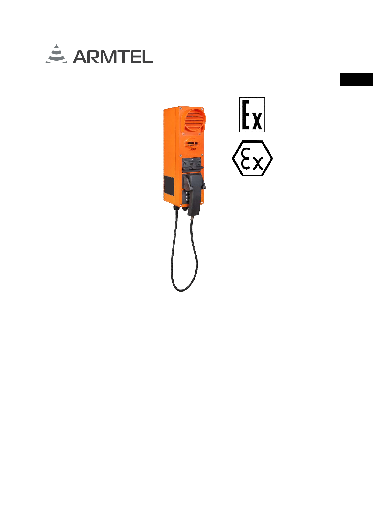
The external appearance of the DWEx-IP2 for two connection with dial pad and
handset is shown in Figure 1. The external appearance of all DWEx-IP2 is shown in
Appendix А.
Figure 1 – External appearance of DWEx-IP2
(versions from RMLT.465311.007-06 to RMLT.465311.007-06.05)
DWEx-IP2 housing structure and material ensure its shock resistance and antistatic
properties. DWEx-IP2 housing and handset (in corresponding versions) are made of
special-purpose fiber-glass reinforced polyester resin. This UF-resistant and highly
conductive material ensure antistatic properties of the components which are
recommended for use in explosion-proof equipment

EXPLOSION-PROOF CALL STATION DWEX-IP2
User Manual
page 12/60 armtel.com
ENG
Rubber gasket seals under the cover, integrated loudspeaker, and microphone, as
well as in Ex type cables of DWEx-IP2 ensure its IP66 ingress protection rating as per
GOST 14254-2015 (IEC 60529:2013). The use of contactless (optical) pairs as sensitive
elements of toggle switches prevents sparks and bad contact due to corrosion. To this end,
keypad and button modules are sealed with rubber gasket. A porous silicone cord with a
diameter of 3 mm is placed in the groove around the cover.
All of the above-mentioned enables to operate the product regardless of its version
in administrative facilities, in open space and (or) in facilities with high levels of humidity,
noise, dust and temperature, as well as presence of smoke, corrosive gases and chemical
vapors in the air.
DWEx-IP2 contains embedded software and configuration data stored in RОM, which
allows it to communicate with other digital communication system users directly, handle
priority connections and manage communication and indication modes. An IP-network
built using standard network equipment is used to facilitate communication.
Within the digital intercom system, the DWEx-IP2 provides the following functions:
−Armtel-IP and SIP protocol support;
−individual simplex communication via SIP and Armtel-IP protocols;
−half-duplex (manual control) communication via SIP protocol;
−indication of busy call, incoming and outgoing calls, unanswered call
notification on direct buttons;
−free programming of the direct buttons (up to 24 pcs.);
−voice message recording via the programmed key with the local function of
fragment recording and playback of voice messages on end-user devices;
−control of the ACM-IP2 analogue subsystem module with “Relay” function;
−free addressing of subscribers for versions with the dial pad;
−connection to the IP network via ADSL or Ethernet 100BaseT;
−enabling organization of a group simplex call;
−local volume adjustment for the integrated loudspeaker and the handset
speaker;
−call implementation on a priority basis (up to 255 priority levels);
−setting up unilateral control and “End” function modes;

EXPLOSION-PROOF CALL STATION DWEX-IP2
User Manual
armtel.com page 13/60
info@armtel.com © Armtel
ENG
−control (commutation) of external actuating devices using an integrated
electro-mechanical relay (lamp-type signaling device).
Configuration of the DWEx-IP2 shall be carried out using the personal computer of
the IPN network administrator on which IPN2 RU.RMLT.00041-01 IPN Config Tool software
configuration application is installed.
EXPLOSION-PROOF CALL STATION DWEX-IP2
User Manual
page 14/60 armtel.com
ENG
1.1.2 Specifications (properties)
Main specification of the DWEx-IP2 are given Table 2.
Table 2 – Main specifications of the DWEx-IP2 (beginning)
Parameters Value
Rated power supply voltage, V
48*
Permissible supply voltage range **, V
from 37 to 57*
Conformity with the PoE class
IEEE 802.3af Class 0
Reverse polarity protection
available
Maximum current consumption, A
0,35*
Maximum power consumption, W
12,95*
Rated power supply voltage of amplifier 25 W, V
48*
Maximum current consumption of amplifier 25 W from the
external source, A
1,3*
Maximum electric power of amplifier 25 W, no less than, W
25*
Maximum switching power the integrated relay (in DWEx-IP2
supply voltage range), W
60*
Bandwidth of LF signal (-3 dB) of the transmit and receive
assembly, Hz
from 400 to 6000***
Sound pressure level at maximum volume, SPL at a distance of
1,0/0,5/0,3 m, at least, dB
96/104/109
Maximum electric power of the integrated loudspeaker amplifier,
no less than, W
0,75
Number of programmed direct connections/functions
up to 24
Communication interfaces
ADSL, ADSL2, ADSL2+
ITU-T G.992.1...992.5
IEEE 802.3u (100BaseT), IEEE
802.3i (10BaseT)
Communication protocols
SIP, Armtel-IP, SNMP
EXPLOSION-PROOF CALL STATION DWEX-IP2
User Manual
armtel.com page 15/60
info@armtel.com © Armtel
ENG
Table 2 – Main specifications of the DWEx-IP2 (end)
Parameters Value
Audio data format (coder/decoder):
−over SIP protocol
G.711A (A-Law)
G.711U (µ-Law)
G.722.1
−over Artmel-IP protocol
Armtel-IP
* Voltage − DC. Versions with amplifier 25 W are powered via a separate 48 V line for
amplifier 25 W.
** Starting VDC: 41 V.
*** Only when using SIP codec G.722.1 or Armtel-IP.
ATTENTION! WHEN CONNECTED TO POWER AND COMMUNICATIONS THE
NECESSARY STRICTLY FOLLOW THE INSTRUCTIONS OF THE OPERATION
DOCUMENTATIONS FOR THE DEVICE! NON-COMPLIANCE WITH THESE
REQUIREMENTS MAY RESULT IN DAMAGE TO THE DEVICE!

EXPLOSION-PROOF CALL STATION DWEX-IP2
User Manual
page 16/60 armtel.com
ENG
1.1.3 Operations conditions
DWEx-IP2 climatic category is NF2 (locations without temperature control. Under
protector visors or tents. Temperature fluctuation for 8 hours not more than 40 °С) as per
GOST 15150-69 with the following ranges of environmental parameters:
−ambient operating temperature range from -40 °Сto +55 °С;
−max. relative air humidity is 100 % at temperature of +25 °C (with moisture
condensation);
−vibration frequency: 0.5 to 55 Hz with the acceleration range of up to 10 m/s2.
DWEx-IP2 ingress protection is IP66 as per GOST 14254-2015 (IEC 60529:2013).
The DWEx-IP2 satisfies requirements for electromagnetic interference resistance
according to GOST 30804.6.2-2013 (IEC 61000-6-2:2005) with performance criteria not
lower than B. Electromagnetic interference from DWEx-IP2 does not exceed standards set
by GOST 30804.6.4-2013 (IEC 61000-6-4:2006).
Note – To ensure the DWEx-IP2 is protected against electromagnetic interference,
the Ethernet connection must be made by a shielded Ethernet cable.
Electric protection class as per GOST IEC 61140-2012: II.
The sign “X”, which in ATEX certificate number, is indicates that this equipment
of protection system is subject to special conditions for save use:
−ambient temperature from -40 °Сto +55 °С

EXPLOSION-PROOF CALL STATION DWEX-IP2
User Manual
armtel.com page 17/60
info@armtel.com © Armtel
ENG
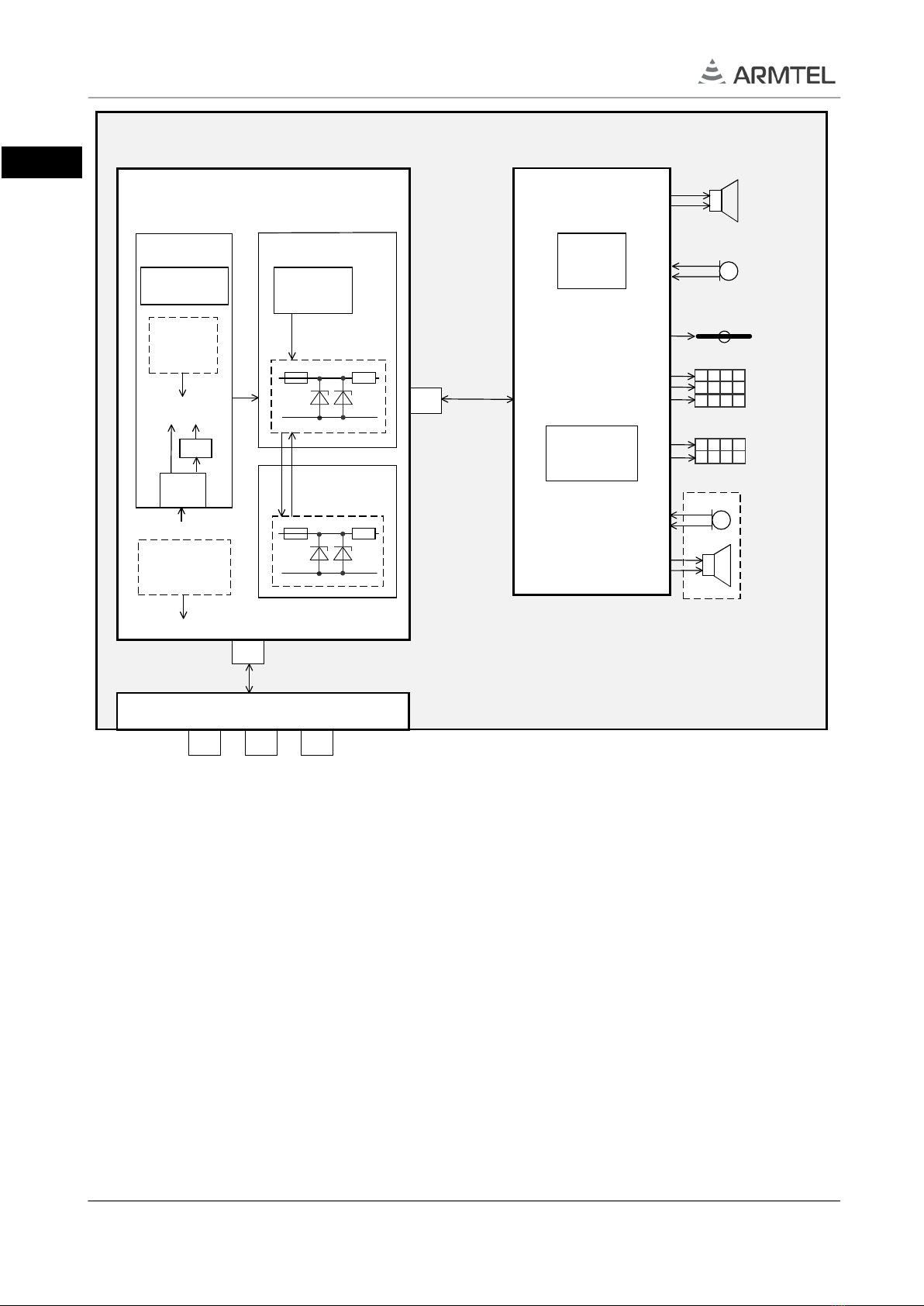
1.1.4 Structure and operation
1.1.4.1 The structural layout of DWEx-IP2 intercom station with explosion protection
components is shown in Figure 2.
Depending on the version, DWEx-IP2 may include the following electronic boards and
modules:
−ADSL IB02 module (for versions with ADSL module, listed in Table 1);
−DART-6UL processor module;
−set of boards, composed of:
a) DW-MB01-IP2 main board and MB01-uSD and MB01-PWR technological
boards;
b) DWEx-IP intrinsic protection board and R-Ex BRD additional intrinsic
protection board;
c) ADSL-EXT board (for versions with ADSL module, see Table 1);
−DW-BC board;
−Kpad board (for versions with dial pad and/or pushbuttons, listed in Table 1);
−amplifier 25 W (for versions with an amplifier 25 W, listed in Table 1).
Note – MB01-uSD, MB01-PWR, ADSL-EXT and Kpad boards are not shown
at Figure 2.
1.1.4.2 Both DW-MB01-IP2 and DW-BC boards are interconnected through DWEx-IP
intrinsic protection board with electric cables that ensure their interaction and functioning
in the communication system. Depending on DWEx-IP2 version, it can be equipped with
ADSL module, amplifier 25 W, and additional Ethernet port. External connection cables are
routed into DWEx-IP2 via explosion-proof cable glands.
1.1.4.3 DW-MB01-IP2 main board receives and processes notification signals and
voice messages, amplifies and transmits them to DW-BC board.
The DW-MB01-IP2 main board connected with technological boards MB01-uSD and
MB01-PWR (not shown on Figure 2), which are only used in the production of and does
not participate in the normal operation DWEx-IP2
1.1.4.4 The DW-BC board ensures processing of signals from key switch modules,
button or keypad modules, controls algorithms for lighting up keys/buttons, amplifies
voice signals from the integrated microphone and the handset microphone, and transmits
the signals to DWEx-IP board for further processing thereof and transmission to the IPN
system.
EXPLOSION-PROOF CALL STATION DWEX-IP2
User Manual
page 18/60 armtel.com
ENG
Figure 2 – DWEx-IP2 structural layout
The following lines can be connected to DWEx-IP2 via the external explosion-proof
cable glands:
−Ethernet interface line with РоЕ;
−additional Ethernet interface line;
−48 V external power supply;
−ADSL interface line;
−external loudspeaker (to the port of amplifier 25 W);
−handset in versions RMLT.465311.007-06…-08.05;
−external actuating device of lamp type (to contacts of the integrated relay).
11
111
11
1
2 3
56 7 8
4
11
1 1 1
11
1
2 3
1 1 1 1
45 6 0
7 8 9 #
*
Handset
Pushbuttons (direct call
buttons)
Dial pad (keypad module)
Two-way toggle
Integrated
microphone
Integrated
loudspeaker
DW-BC board
Flameproof enclosure (d)
Ех-cable glands
Microphone
amplifier
Increased safety (е)
Microprocessor
Ех-cable glands
Ex-terminal block
Ех-cable glands
Intrinsic safe circuits “ib”
Amplifier 25 W
Intrinsic
protection unit “ib”
DWEx-IP Intrinsic
protection board
DW-MB01-IP2
main board
48 V
Secondary
power
supply
DC/DC
5 V 3,3 V
ADSL module
DART-6UL
processor module
Explosion-proof box Ex-d
R-Ex-BRO intrinsic
protection board
Amplifier
0,5 W
5 V
Intrinsic
protection unit “ib”
This manual suits for next models
1
Table of contents
Other ARMTEL Cordless Telephone manuals


