ARMTEL DW-IP2 User manual
Document version 12
26.30.23.000
2022
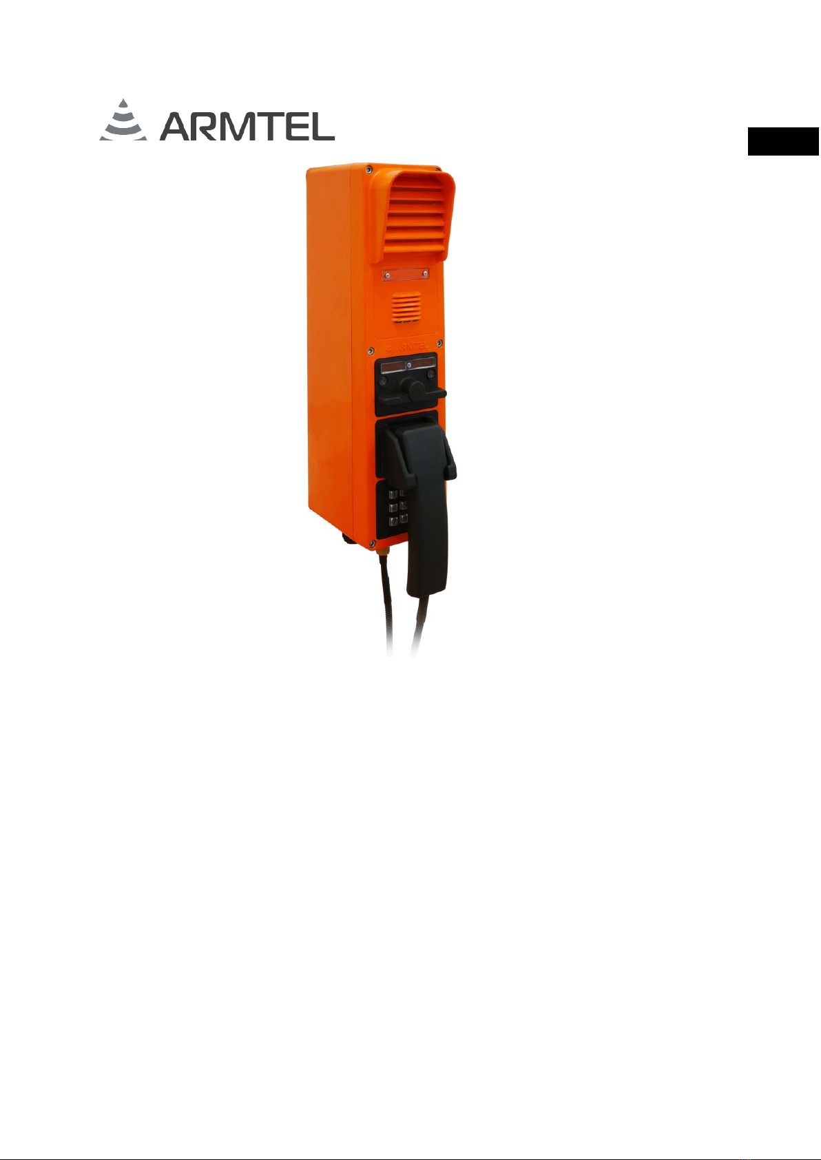
DW-IP2
Weatherproof call station
RMLT.465311.006UM1
User Manual
ENG

armtel.com
© Armtel info@armtel.com
DW-IP2 WEATHERPROOF CALL STATION
User Manual
armtel.com page 1/48
info@armtel.com © Armtel
ENG
INTRODUCTION
This User Manual is intended for introducing «DW-IP2 Weatherproof call station»
including versions of RMLT.465311.006-100...RMLT.465311.006-207 (Table 1), manufactured
by Armtel LLC and is intended to familiarize the User with the device and the procedure for
its operation at the installation site.
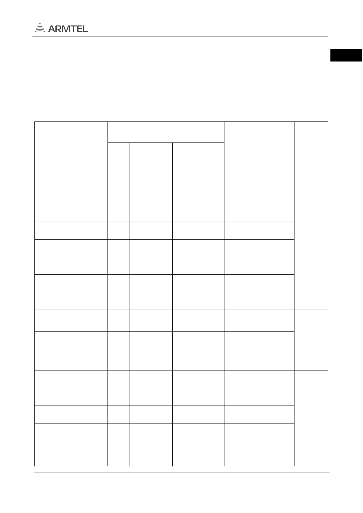
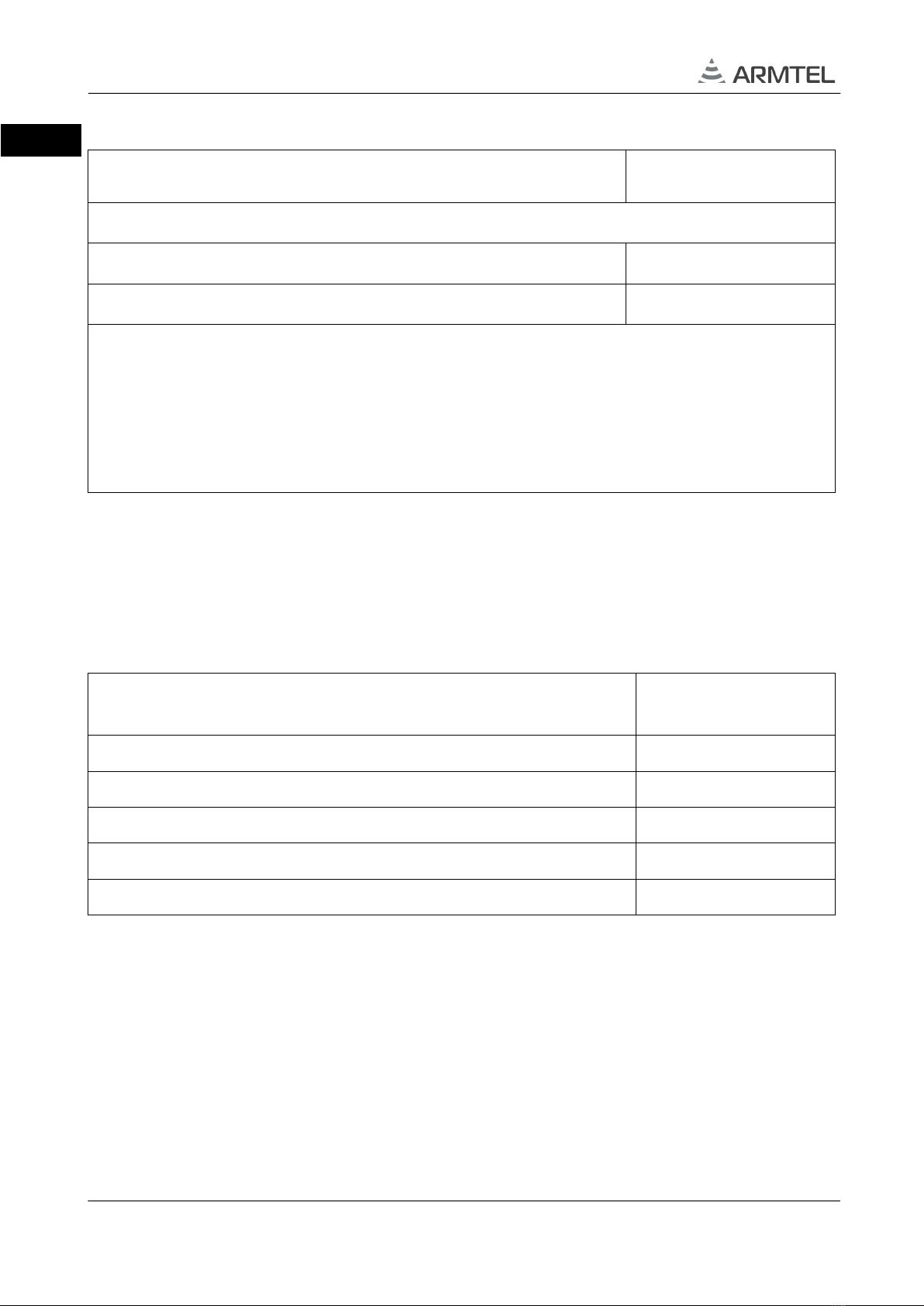
Table 1 – Versions of the DW-IP2 (beginning)
Version identification
(without optional
equipment)
Version identification
with optional equipment
Version
specification
(without optional
equipment)
Overall dimensions,
max, mm
Amplifier
25 W
ADSL
module
Amplifier 25 W,
ADSL module
Additional
Ethernet port
Additional
Ethernet port,
amplifier 25 W
RMLT.465311.006-100 -118 -136 -154 -172 -190 2 connections
see
Figure
2a)
-101 -119 -137 -155 -173 -191 4 connections
-102 -120 -138 -156 -174 -192 6 connections
-103 -121 -139 -157 -175 -193 8 connections
-104 -122 -140 -158 -176 -194 16 connections
-105 -123 -141 -159 -177 -195 24 connections
-106 -124 -142 -160 -178 -196
2 connections,
handset, dial pad
see
Figure
2b)
-107 -125 -143 -161 -179 -197
8 connection,
handset, dial pad
-108 -126 -144 -162 -180 -198 handset, dial pad
-109 -127 -145 -163 -181 -199 10 connections
see
Figure
2a)
-110 -128 -146 -164 -182 -200 18 connections
-111 -129 -147 -165 -183 -201 12 connections
-112 -130 -148 -166 -184 -202
2 connections,
dial pad
-113 -131 -149 -167 -185 -203
4 connections,
dial pad
DW-IP2 WEATHERPROOF CALL STATION
User Manual
page 2/48 armtel.com
ENG
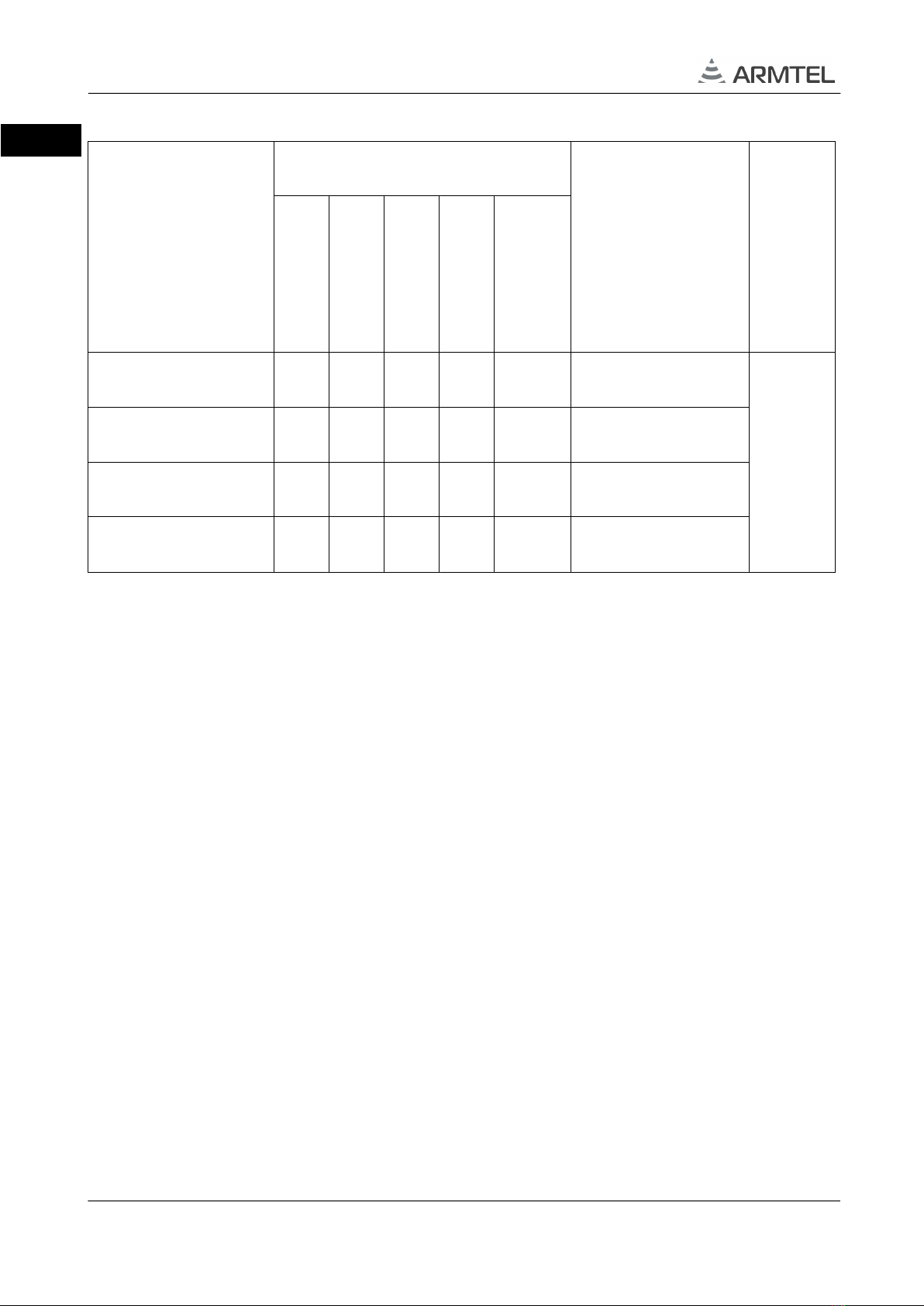
Table 2 – Versions of the DW-IP2 (end)
Version identification
(without optional
equipment)
Version identification
with optional equipment
Version
specification
(without optional
equipment)
Overall dimensions,
max, mm
Amplifier
25 W
ADSL
module
Amplifier 25 W,
ADSL module
Additional
Ethernet port
Additional
Ethernet port,
amplifier 25 W
-114 -132 -150 -168 -186 -204
8 connections,
dial pad
see
Figure
2a)
-115 -133 -151 -169 -187 -205
10 connections,
dial pad
-116 -134 -152 -170 -188 -206
16 connections,
dial pad
-117 -135 -153 -171 -189 -207
With keys SOS and
INFO, info module
DW-IP2 Weatherproof call station is the subscriber equipment to use at industrial and
transportation enterprises within digital Intercom and Public Address / General Alarm
(PA/GA) communication system IPN manufactured by Armtel LLC.
Short name of the product – DW-IP2.
DW-IP2 can be used in chemical, mining, oil and gas, metal processing and wood
processing industries, and other.
Maintenance personnel for DW-IP2 shall be appointed by the management at
the installation site.
The maintenance personnel shall be required to know the operating procedure of
DW-IP2 to the extent provided for by the User Manual.
Duties of the maintenance personnel shall include maintenance of DW-IP2 in
accordance with this User Manual
ATTENTION! In connection with systematic work to improve the design and
manufacturing technology, it is possible some discrepancy between the description and the
supplied product, which does not affect its operation or maintenance.

DW-IP2 WEATHERPROOF CALL STATION
User Manual
armtel.com page 3/48
info@armtel.com © Armtel
ENG
SAFETY PROVISIONS
During installation and operation, observe safety precautions laid out in “Occupational
safety rules when operating electrical installations” when working with electrical receivers
with voltage of up to 1000 V.
In order to ensure fire safety, follow the following rules:
−before connecting the product to the power supply, make sure the power and
communication cables are properly insulated;
−protect power and communication cables from damage.
To avoid electric shock, do not:
−turning on the device with damaged power and interface cables.
ATTENTION! NEVER DISMANTLE THE PRODUCT CONNECTED TO MAINS.
The safety provisions for specific operations described in this manual are marked with:

DW-IP2 WEATHERPROOF CALL STATION
User Manual
page 4/48 armtel.com
ENG
CONTENTS
INTRODUCTION.................................................................................................................................................................... 1
SAFETY PROVISIONS........................................................................................................................................................... 3
CONTENTS .............................................................................................................................................................................. 4
1 DESCRIPTION AND OPERATION................................................................................................................................. 6
1.1 Basic parameters and characteristics (properties) ...................................................................................... 6
1.1.1 Features ............................................................................................................................................................. 6
1.1.2 Main spetifications ........................................................................................................................................ 8
1.1.3 Operations conditions................................................................................................................................11
1.1.4 DW-IP2 design ..............................................................................................................................................12
1.1.5 Marking............................................................................................................................................................17
1.1.6 Package............................................................................................................................................................18
1.2 Description and operation of product components................................................................................19
1.2.1 General information....................................................................................................................................19
1.2.2 Integrated amplifiers ..................................................................................................................................19
1.2.3 ADSL module.................................................................................................................................................20
1.2.4 Dial pad (keypad module) ........................................................................................................................20
1.2.5 Pushbuttons (direct call buttons)...........................................................................................................20
1.2.6 «SOS» and «INFO» modules....................................................................................................................21
1.2.7 Handset............................................................................................................................................................21
1.2.8 Electrical mechanical relay........................................................................................................................21
1.2.9 CCS-DW-IP2 main board ..........................................................................................................................22
1.2.10 DART-6UL processor module ...............................................................................................................22
1.2.11 DW-BC board..............................................................................................................................................23
2 INTENDED USE ................................................................................................................................................................24
2.1 Operating limits .....................................................................................................................................................24
2.2 Safety precautions.................................................................................................................................................24
2.3 Preparation for use ...............................................................................................................................................25
2.4 Installation, connection and dismantling .....................................................................................................26
2.4.1 Installation ......................................................................................................................................................26
2.4.2 Connection .....................................................................................................................................................27
2.4.3 Dismantling ....................................................................................................................................................28

DW-IP2 WEATHERPROOF CALL STATION
User Manual
armtel.com page 5/48
info@armtel.com © Armtel
ENG
2.5 Operation .................................................................................................................................................................30
2.5.1 Configuration.................................................................................................................................................30
2.5.2 Product operating modes.........................................................................................................................31
2.5.3 Procedure for monitoring the operability of the product............................................................33
2.5.4 Troubleshooting...........................................................................................................................................34
3 MAINTENANCE................................................................................................................................................................35
3.1 General guidelines ................................................................................................................................................35
3.2 Safety precautions.................................................................................................................................................35
3.3 Maintenance procedure......................................................................................................................................35
3.4 Checking operability ............................................................................................................................................36
3.4.1 Checking the audio path...........................................................................................................................36
3.4.2 Functional check for keys/buttons and indicators ..........................................................................36
4 PEPAIR…………………………………………………………………………………………………………………………………………...37
5 STORAGE............................................................................................................................................................................37
6 TRANSPORTATION.........................................................................................................................................................38
7 DISPOSAL...........................................................................................................................................................................38
APPENDIX A (reference) External appearance of DW-IP2 versions.................................................................39
APPENDIX B (reference) PoE function in DW-IP2...................................................................................................42
APPENDIX C (reference) Connection...........................................................................................................................44
APPENDIX D (reference) Light indication..................................................................................................................48

DW-IP2 WEATHERPROOF CALL STATION
User Manual
page 6/48 armtel.com
ENG
1 DESCRIPTION AND OPERATION
1.1 Basic parameters and characteristics (properties)
1.1.1 Features
DW-IP2 Weatherproof call station is the subscriber equipment of a wired public
address system and is designed for use in distributed and centralized (based on the
dedicated SIP server manufactured by Armtel LLC) public address systems in industrial
facilities and on transportation.
DW-IP2 has a modular design, and depending on the modules installed. The version
may vary in accordance with Table 1.
The external appearance of all DW-IP2 versions is shown in Appendix А.
Characteristics of DW-IP2 enable to the operation of the product regardless of its
version in administrative facilities, in open spaces and (or) in facilities with high levels of
humidity, noise, dust and temperature, as well as presence of smoke, corrosive gases and
chemical vapors in the air.
DW-IP2 contains embedded software and configuration data stored in RОM, which
allows it to communicate with other digital communication system users directly, handle
priority connections and manage communication and indication modes. An IP-network built
using standard network equipment is used to facilitate communication.
Within the digital intercom system IPN, DW-IP2 provides the following functions:
−Armtel-IP, SIP, SNTP and SNMP protocol support;
−individual simplex communication via SIP and Armtel-IP protocols;
−half-duplex (manual control) communication via SIP protocol;
−indication of busy call, incoming and outgoing calls, unanswered call notification
on direct buttons;
−free programming of the direct buttons (up to 24 pcs.);
−automatic playback of the message on the side of the called subscriber, when
pressing the direct call button of the outgoing subscriber, the "parrot" function;
−selector: a frequent case of a conference for simplex devices, with the
following features, all participants in the selector always hear only one of the
participants, the organizer of the selector can give and take away the right to
answer from the participant, when the participant of the selector answers, his
answer is heard by all participants of the selector;

DW-IP2 WEATHERPROOF CALL STATION
User Manual
armtel.com page 7/48
info@armtel.com © Armtel
ENG
−circular: a special case of a conference for simplex devices, with the following
features: all participants in the circular hear only the organizer of the circular,
the organizer can give and take away the right to answer from the participant
of the circular, when the participant answers, his answer is heard only to the
organizer, each subscriber can independently leave the circular;
−implementation of duplex communication between several subscribers, in which
all conference participants simultaneously hear all participants, and also have
the ability to speak;
−duplication of incoming / outgoing traffic to the IP address specified in the
parameters of the "call registration" function;
−- SNMP support provides the ability to notify the server about any events on the
device using broadcast packets that are sent by the device to the specified IP-
address;
−voice message recording via the programmed key with the local function of
fragment recording and playback of voice messages on end-user devices;
−control of the ACM-IP2 analogue subsystem module with “Relay” function;
−free addressing of subscribers for versions with dial pad;
−connection to the IP network via ADSL or Ethernet 100BaseT;
−enabling organization of a group simplex call;
−call implementation on a priority basis (up to 255 priority levels);
−setting up unilateral control and “End” function modes;
−control (commutation) of external actuating devices using an integrated electro-
mechanical relay (lamp-type signaling device).
Configuration of the DW-IP2 shall be carried out using the personal computer of
the IPN network administrator on which RU.RMLT.00041-01 IPN Config Tool software is
installed.
DW-IP2 WEATHERPROOF CALL STATION
User Manual
page 8/48 armtel.com
ENG
1.1.2 Main spetifications
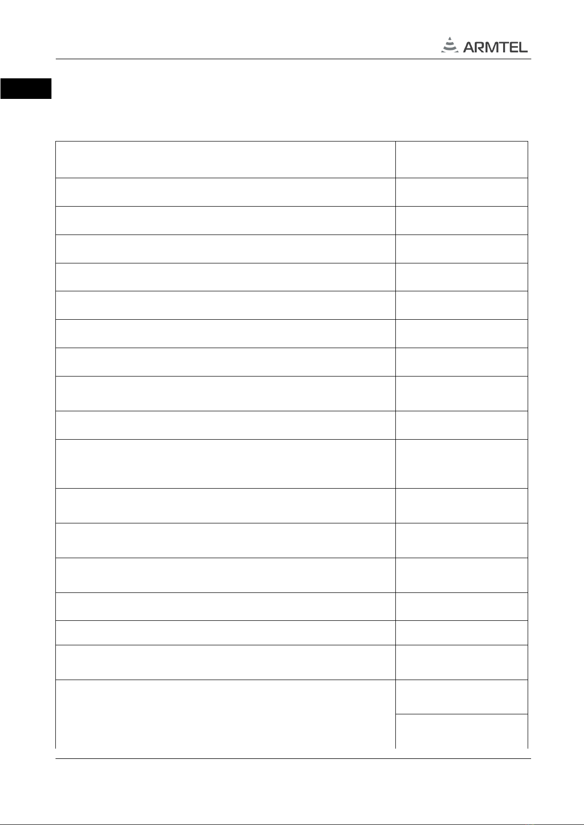
Main specifications are provided in Table 2.
Table 2 – Main specifications and performance characteristics (beginning)
Parameter Value
Rated voltage*, V 48
Supply voltage range*, V from 37 to 57
Conformity with the PoE class IEEE 802.3af Class 0
Revers polarity protection available
Maximum current consumption*, max, А0,28
Maximum power consumption*, max, W 12
Rated voltage of the external power supply of the amplifier 25 W*, V 48
Maximum current consumed by the amplifier is 25 W from an
external power source*, max, A
1
Maximum electrical power of the amplifier is 25 W*, not less than, W 25
Maximum power of integral relay when external execution units
(devices) are connected (in supply voltage range of DW-IP2)*,
max, W,
60
Bandwidth of LF signal (-3 dB) of the transmit and receive assembly
(excluding integrated loudspeaker and microphone), Hz
from 300 to 14000
Sound pressure level of the integrated loudspeaker at maximum
volume, SPL at a distance of 1,0/0,5/0,3 m, at least, dB
103/110/114
Maximum electrical power of the built-in speaker amplifier, not less
than, W
2
Number of programmed direct connections/functions up to 24
Resistance of the power supply line when connected via ADSL, max, Ohm
49
Total duration of sound fragments stored in the device memory,
no less than, min
1500
Communication interfaces
ADSL, ADSL2, ADSL2+
ITU-T G.992.1...992.5
IEEE 802.3u (100BaseT),
IEEE 802.3i (10BaseT)

DW-IP2 WEATHERPROOF CALL STATION
User Manual
armtel.com page 9/48
info@armtel.com © Armtel
ENG
Table 2 – Main specifications and performance characteristics (continuation)
Parameter Value
Communication protocols
SIP, Armtel-IP, SNMP,
SNTP
Audio data format (coder/decoder)):
- over SIP protocol
G.711A (A-Law)
G.711U (µ-Law)
G.722.1
- over Armtel-IP protocol Armtel-IP
Weight***, kg, max:
- RMLT.465311.006-100, -103, -117, -172, -175,-189
5,25
- RMLT.465311.006-101, -102, -104, -105, from РМТ.465311.006-109
to RMLT.465311.006-116, -135, -136, -137, -139, -140, -145, -148,
-153, -173, -176, -181, -184
5,50
- RMLT.465311.006-118, -119, -121, -122, -127, -130, -138, -141, -146,
-147, -149, from RMLT.465311.006-150 to RMLT. RMLT.465311.006-
154, -157 -171, -174, -177, -182, -183, from RMLT.465311.006-185 to
RMLT.465311.006-188, -190, -193, -207
5,75
- RMLT.465311.006-108, -120, -123, -129, -128,
from RMLT.465311.006-131 to RMLT.465311.006-134, -155, -
158,
-163, -166, -180, -191, -192, -194, -195, -199, from RMLT.465311.006-
200 to RMLT.465311.006-206
6,00
- RMLT.465311.006-106, -107, from RMLT.465311.006-142 to
RMLT.465311.006-144, -156, -159, -164, -165,
from RMLT.465311.006-167 to RMLT.465311.006-170, -178, -179
6,25
- from RMLT.465311.006-124 to RMLT.465311.006-126, -162, -198
6,50
- RMLT.465311.006-160, -161,-196, -197
6,70
Electrical specifications of the amplifier 25 W (beginning)
Rated voltage*, V
from 37 to 57
Supply voltage range*, V
48
Maximum current consumption*, max, А
1
Rated-power output, W
25
DW-IP2 WEATHERPROOF CALL STATION
User Manual
page 10/48 armtel.com
ENG
Table 2 – Main specifications and performance characteristics (end)
Parameter Value
Electrical specifications of the amplifier 25 W (beginning)
Nominal output voltage, VAC
100
Load resistance, no less than, Ohm
400
* Voltage - DC. Versions with amplifier 25 W are powered via a separate 48 V line for
amplifier 25 W.
** Only for direct calls without using sound files (except for local sound files with a sampling
rate of 32 kHz (located in the local memory of the device) via SIP protocol and when using the SIP
codec G.722.1C.
When using the Armtel-IP protocol, the bandwidth is from 300 to 6800 Hz.
*** Without package and mounting kit.
The design and material of the DW-IP2 housing provide protection from external
influences. The design and material of the DW-IP2 housing provide impact resistance, have
good conductivity, absence of static electricity, and chemical resistance. The material has
resistance to ultraviolet radiation, oil and gas resistance, resistance to chemical environment,
as indicated in Table 3.
Table 3 –Chemical resistance of the material
Chemical environment Stability
Diluted mineral acids, 3% solution stable
Diluted acetic acid, 3% solution stable
Alkalis, 50% solution stable
Ammonia, 10% aqueous solution stable
Alcohols stable

DW-IP2 WEATHERPROOF CALL STATION
User Manual
armtel.com page 11/48
info@armtel.com © Armtel
ENG
1.1.3 Operations conditions
The climatic category according to GOST 15150-69 is NF2 (locations without
temperature control. Under protector visors or tents. Temperature fluctuation for 8 hour not
more 40 °C) with the following ranges of environmental parameters:
−operating temperature range: from −55 °Сto +55 °С;
−upper value of amber air humidity up to 100 % (at + 25 °C with moisture
condensation);
−vibration frequency from 0,5 to 55 Hz with peak acceleration amplitude of
10 m/s2.
DW-IP2 ingress protection is IP66 as per GOST 14254-2015 (IEC 60529:2013).
The DW-IP2 satisfies requirements for electromagnetic interference resistance
according to GOST 30804.6.2-2013 (IEC 61000-6-2:2005) with performance criteria not lower
than B.
Note – Performance criteria when DW-IP2 powered via PoE injector is not lower then
A, via terminal block is not lower then B. Under the influence of electrostatic discharges on
the product enclosure from 2 kV to 6 kV, when connected to the PoE injector, it is necessary
to connect by shielded cable to an earthed PoE injector.
Electromagnetic interference from DW-IP2 does not exceed standards set by
GOST 30804.6.4-2013 (IEC 61000-6-4:2006).
Electric protection class as per GOST IEC 60065-2013 – II.
DW-IP2 WEATHERPROOF CALL STATION
User Manual
page 12/48 armtel.com
ENG
1.1.4 DW-IP2 design
1.1.4.1 DW-IP2 overall dimensions
Figure 1 shows the appearance of DW-IP2 versions -100, -136, -154, -172, -190
(Figure 1a) and -106,-124,-142,-160,-178 (Figure 1b).
The appearance of the DW-IP2 of all versions is given in Appendix A.
The overall dimensions shown in Figure 1a) refer to DW-IP2 versions -100, -136,
-154, -172, -190. The overall dimensions shown in Figure 1b) also apply to the DW-IP2
versions of the RML.465311.006-106...-108, -124...-126, -142...-144, -160...-162, -178...-180,
-196...-198.
a) excluding versions
RMLT.465311.007-106-…-108, -124…-126,
-142…-144, -160…-162, -178…-180,
-196…-198
b) versions
RMLT.465311.007-106-…-108,
-124…-126, -142…-144, -160…-162,
-178…-180, -196…-198
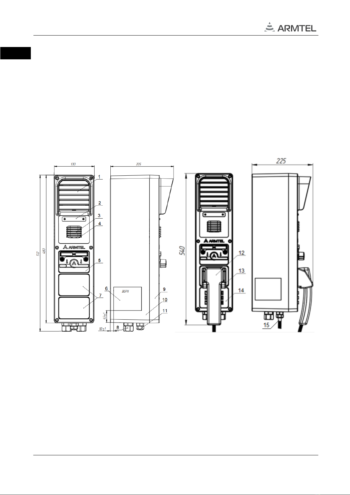
1 – loudspeaker; 2 - marking panel; 3 – microphone; 4 – LEDs for indication DW-IP2 ;
5 – two-way toggle; 6 – nameplate; 7 – plugs; 8 – cable glands for cables 8 - 17 mm dia (2 pcs.);
9 – cover; 10 – enclosure; 11 –cable gland for cable 6 - 13 mm dia; 12 – handset; 13 – bracket with reed
relay; 14 – dial pad (keypad module); 15 – metal jacket fixing kit
Figure 1 – External appearance and overall dimensions of DW-IP2
1.1.4.2 The rear side of DW-IP2 enclosure is equipped with M6 thread bushings for
fastening to the workstation with the brackets from the supply package (see Section 2.4
“Installation, connection, and dismantling”). Cables for DW-IP2 connection with the external
DW-IP2 WEATHERPROOF CALL STATION
User Manual
armtel.com page 13/48
info@armtel.com © Armtel
ENG
diameter from 8 to 17 mm (8) and/or from 6 to 13 mm (11) are routed through cable glands.
In versions with the handset (see Figure 2 b), see Table 1), one of cable gland (8) is used to
kit for the flexible metal tubing of the handset.
Cover (9) is mounted onto the enclosure (10) from the front side. The cover is fastened
to of DW-IP2 enclosure with six anti-loosening screws М6. Integrated loudspeaker (1) is
placed at the top of the cover with marking panel (2) below for inserting a label with
the subscriber on-line identification.
Microphone (3) is located below the marking panel, below are the indicators (4). The
speaker and the microphone are protected from mechanical damage and direct ingress of
small particles and water with shaped grills of the cover. Depending on DW-IP2 version, one
to three modules with two-way toggle (5) or dial pad (14)/pushbuttons (direct call
buttons)/buttons/handset with bracket with reed relay (12) can be mounted in the lower part
of the cover.
LED indicators of operating modes are located above the switches with marking
nameplate for inserting replaceable labels with identification of programmed functions
performed by DW-IP2 in the corresponding positions of the two-way toggle. Plugs (7) are
inserted into empty module seats.
Nameplate (6) with labeling information is fastened to the lateral surface of
the enclosure (see 1.1.5).
1.1.4.3 DW-BC board is fixed by supports on inside of the cover.
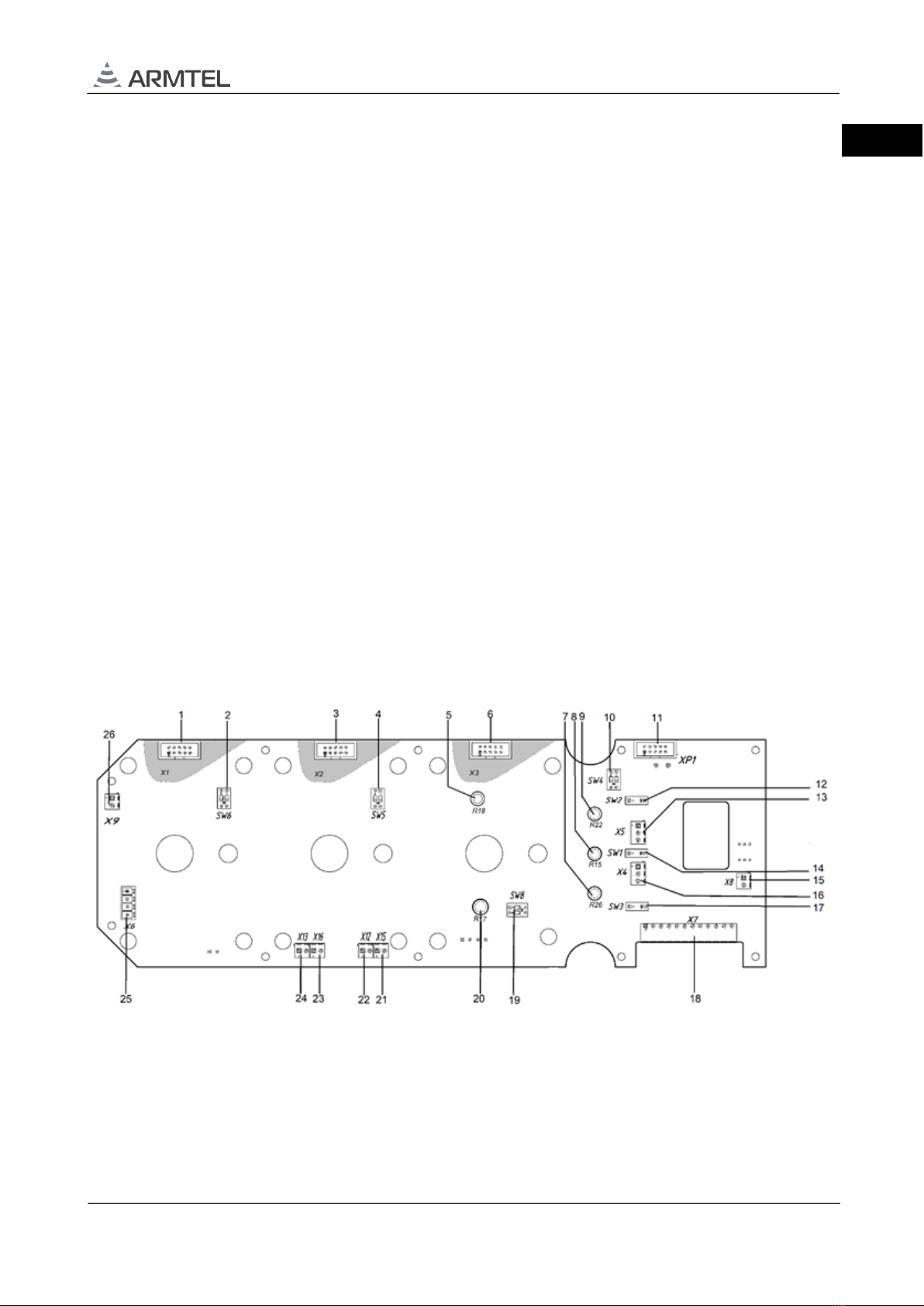
Figure 2 – External appearance of DW-BC board
The board comprises the following components:
1, 3, 6 – sockets «X1», «X2» and «X3» for two-way toggle, pushbuttons and dial pad
(see back side of the board);

DW-IP2 WEATHERPROOF CALL STATION
User Manual
page 14/48 armtel.com
ENG
2, 4, 10 – («SW6», «SW5», «SW4») - two-positions DIP-switches for the type of installed
modules in the corresponding cover compartments. The correspondence of the switch
positions and the installed modules is shown in Table 4, where "x" is the DIP-switch number.
Table 4 – DIP-switch positions
SWx.1 SWx.2 Type of installed module
OFF OFF
Plug or dial pad (keypad
module)
ON OFF
Two-way toggles (for two
connections)
OFF ON
Pushbuttons (8 direct keys
module)
ON ON
Handset and a cradle
hermetic sensor
5 – «R18» – volume control of the main amplifier (VOLUME INT) – not used;
7 – «R26» microphone handset sensitivity control (MIC HS);
8 – «R15» built-in microphone sensitivity control (MIC INT);
9 – «R22» external microphone sensitivity control (MIC EXT);
11 – technological socket «XP1» for programming the board;
12 – switch «SW2» to select the type of microphone caps used in the remote
microphone:
1) in the ON position – electret microphone (remote with tangent);
2) in the OFF position, there is no dynamic microphone or microphone.
13 – socket «X5» for external microphone with tangent;
14 – switch «SW1» to select the type of microphone caps used in the front panel:
1) in the ON position – electret microphone (built-in);
2) in the OFF position, there is no dynamic microphone or microphone.
15 – socket «X8» for built-in speaker;
16 – socket «X4» for built-in microphone;
17 – switch «SW3» to select the type of microphone caps used in the handset:
1) in the ON position – electret microphone (tube);
2) in the OFF position, there is no dynamic microphone or microphone.

DW-IP2 WEATHERPROOF CALL STATION
User Manual
armtel.com page 15/48
info@armtel.com © Armtel
ENG
18 – socket «X7» for connect to main board;
19 – «SW8» – a two-position switch for setting the sensitivity of a microphone amplifier
with AGC, common to all microphones. The correspondence of the position of the switches
and the sensitivity of the AGC is shown in Table 5.
Table 5 – Microphone sensitivity selection
SW8.1 SW8.2 Microphone sensitivity
OFF OFF Max
ON
OFF
Medium
OFF
ON
Low
ON
ON
Min
20 – «R17» volume control of an external loudspeaker (VOLUME EXT) – not used;
21, 22 – socket «X12» (X12 = X12 (button) + X15 (indication)) for button module
«INFO» – not used;
23, 24 – socket «X13» (X13 = X13 (button) + X16 (indication)) for button module
«SOS» – not used
25 – socket «X6» for handset;
26 – socket «X9» for bracket with reed relay.
1.1.4.4 Inside DW-IP2 enclosure (see Figure 3) is mounted the chassis (5), made of sheet
metal not less than 1 mm thick. On the chassis are installed threaded columns for fasten
CCS-DW-IP2 main board (3), threaded bushings for fasten a cooling radiator (is fastened
under the СCS-DW-IP2 board, not shown on Figure 5) иadditional amplifier 25 W (2).
NE01 board (4) or ADSL module (installed instead the NE01 board, not shown on
Figure 5) are mounted on the CCS-DW-IP2 main board by М2 threaded bushings. Also,
the cooling radiator is installed above the ADSL module through the M2 threaded bushings.
The standard 35 mm DIN rail (1) is fasten in the DW-IP2 enclosure by M4 screws
through the threaded bushings.
For easy connection DW-IP2, 10 pcs. terminal blocks (7) are fixed to DIN rail.
The terminal blocks are designed for connection of 28 to 12 AWG conductors (with the
external diameter of 0.321 to 2.053 mm and the cross-section area of 0.081 to 3.31 mm2).
Input and output electrical lines from DW-IP2 are connected via cable glands (6) −
1 pcs. for cable 6-13 mm dia and 2 pcs. for cable 6-13 mm dia.
DW-IP2 WEATHERPROOF CALL STATION
User Manual
page 16/48 armtel.com
ENG
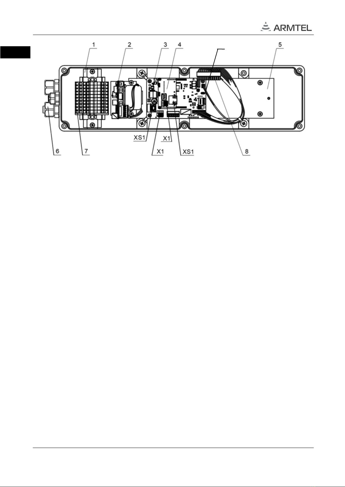
1 – DIN rail, 2 – amplifier 25W, 3 – CCS-DW-IP2 main board, 4 – NE01 board, 5 – chassis,
6 – cable glands, 7 – terminal blocks, 8 – cable for DW-BC board connection, 9 – “BTN” button
XS1 (CCS-DW-IP2 main board) – socket RJ45 type with PoE, XS1 (NE01 board) – socket RJ45 type
without PoE, Х1 (CCS-DW-IP2 main board) – alternative socket for Ethernet line connection,
Х1 (NE01 board) – socket for Ethernet line connection
Note – The connection interfaces are described in Appendix C
Figure 3 – External appearance of the DW-IP2 enclosure (example)
(versions without handset, with additional Ethernet port and amplifier 25 W)
Via the cable glands can be connected to the DW-IP2:
−Ethernet line with PoE function;
−additional Ethernet line;
−external power supply 48 VDC;
−ADSL line;
−an external loudspeaker (to the out of the amplifier 25 W);
−an external actuating devices (using pins of the integrated electro-mechanical
relay).
The handset in the appropriate versions (see Table 1) is connected via the kit for the
flexible metal tubing of the handset, which is installed instead of the cable gland for cable
8-17 mm dia.
The connection of the mainboard with the DW-BC board is made by a special cable.
Spare cable glands are blanked with plugs (now shown in Figure 2).
9

DW-IP2 WEATHERPROOF CALL STATION
User Manual
armtel.com page 17/48
info@armtel.com © Armtel
ENG
In DW-IP2 versions without amplifier 25 W (see Table 1) the CCS-DW-IP2 main
board can be connected to the PoE power supply source (injector) as a device
complying with the standard PoE IEEE 802.3af. In versions with amplifier 25 W
the CCS-DW-IP2 main board can be connected with the amplifier to one 48V power supply
source with proper power rating. If the CCS-DW-IP2 main board is powered from PoE
injector, amplifier 25 W shall be powered from a separate source.
Rubber gasket seals under the cover, integrated loudspeaker, and microphone, two-
way toggle, as well as in cables glands of DW-IP2 ensure its IP66 ingress protection rating
as per GOST 14254-2015 (IEC 60529:2013).
Integrated loudspeaker has a diaphragm that is resistant to moisture and vapors of
aggressive chemicals. The use of contactless (optical) pairs as sensitive elements of toggle
switches prevents sparks and bad contact due to corrosion. To this end, pushbuttons and
dial pad are sealed with rubber gasket. A porous silicone gasket with a diameter of 3 mm is
placed in the groove around the cover.
1.1.5 Marking
On the DW-IP2 enclosure is placed bilingual nameplate
The nameplate contains the following information:
−name, trademark and reference information of the manufacturer;
−product name and description;
−rated supply voltage value;
−electric protection class marking according to GOST IEC 60065-2013;
−commercialization mark for products on the market of Customs Union member
states;
−permissible operating temperature range;
−degree of protection provided by enclosures (IP code);
−special waste disposal mark;
−product serial number;
−MAC addresses;
−date of manufacture;
−marking «Made in Russia».
−other information if necessary.
The serial number and MAC addresses are unique for each product.

DW-IP2 WEATHERPROOF CALL STATION
User Manual
page 18/48 armtel.com
ENG
1.1.6 Package
The DW-IP2 with the assembly kit and documents, which come with the supply
package, is packed in consumer package (cardboard box) according to GOST 23088-80.
A label in Russian language and English language is glued onto the consumer package,
said label containing the following inscriptions and symbols:
−product name and description;
−name, trademark and reference information of the manufacturer;
−handling symbols according to GOST 14192-96 and CU TR 005/2011;
−commercialization mark for products on the market of Customs Union member
states;
−serial number and date of manufacture.
The package is made according to the drawings of the product manufacturer and
enables storage of the DW-IP2, provided requirements set in Section 5 are met.
For shipment of the DW-IP2 from the manufacturer, consumer package contents are
placed in the package place, which ensures protection from mechanical damage, direct
ingress of atmospheric precipitation, dust and solar radiation during transportation.
Other manuals for DW-IP2
1
Table of contents
Other ARMTEL Telephone manuals


