ARMTEL DTS-TOP User manual

DTS-TOP Multifunctional
Telephone
RMLT.465484.002UM
User Manual
Document version 10 26.30.23.000
2022
ENG

armtel.com
© Armtel info@armtel.com

DTS-ТОР MULTIFUNCTIONAL TELEPHONE
User Manual
armtel.com page 1/51
info@armtel.com © Armtel
INTRODUCTION
This User Manual applies to «DTS-ТОР multifunction digital phone» RMLT.465484.002
manufactured by Armtel LLC, and is intended to familiarize the User with the device and the
procedure for its operation at the installation site.
Is the subscriber equipment for operation within digital intercom communication
system controlled by DCN-2 central exchange. system manufactured by Armtel LLC.
Short name of product – DTS-TOP.
Maintenance personnel for DTS-TOP shall be appointed by the management at
the installation site.
The maintenance personnel shall be required to know the operating procedure of
DTS-TOP to the extent provided for by the User manual.
The maintenance personnel shall be required to know the operating procedure of
DTS-TOP to the extent provided for by the User manual.
Example of DTS-TOP designation during ordering and in documentation:
«DTS-ТОР multifunction digital phone» RMLT.465311.004 or RMLT.465311.004-01
depending of product version (see 1.1.1).
ATTENTION! In connection with systematic work to improve the design and
manufacturing technology, it is possible some discrepancy between the description and
the supplied product, which does not affect its operation or maintenance.
ENG

DTS-ТОР MULTIFUNCTIONAL TELEPHONE
User Manual
page 2/51 armtel.com
SAFETY PROVISIONS
During installation and operation observe the safety measures specified by local codes
and regulations on electrical safety.
During installation and operation, observe safety precautions laid out in “Occupational
safety rules when operating electrical installations” when working with electrical receivers
with voltage of up to 1000 V.
To avoid electric shock, do not:
−turning on the device with damaged power and interface cables or connectors.
−operate the product with damaged power supply and communication cables, or
using RJ-45 socket.
−connect and disconnect the sockets and plugs for connecting the headset and
EC-TOP units only when the power and communication cables are disconnected.
−never disassemble the product connected to the power and interface bus. Install
and connect the product only when the assembly is de-energized.
ATTENTION! NEVER DISMANTLE THE PRODUCT CONNECTED TO MAINS.
Installation and connection of the product only in a de-energized state.
Do not use the product in rooms with high humidity (more than 80 %) or conductive
dust.
ВIn order to ensure fire safety, follow the following rules:
−before connecting the product to the power supply, make sure the power and
communication cables are properly insulated;
−protect power and communication cables from damage.
The safety provisions for specific operations described in this manual are marked with:
ENG

DTS-ТОР MULTIFUNCTIONAL TELEPHONE
User Manual
armtel.com page 3/51
info@armtel.com © Armtel
CONTENTS
INTRODUCTION.................................................................................................................................................................... 1
SAFETY PROVISIONS........................................................................................................................................................... 2
CONTENTS .............................................................................................................................................................................. 3
1 DESCRIPTION AND OPERATION................................................................................................................................. 5
1.1 Product description and operation .................................................................................................................. 5
1.1.1 Features ............................................................................................................................................................. 5
1.1.2 Main specifications........................................................................................................................................ 7
1.1.3 Operations conditions.................................................................................................................................. 8
1.1.4 Scope of supply............................................................................................................................................... 9
1.1.5 Design...............................................................................................................................................................10
1.1.6 Labeling ...........................................................................................................................................................13
1.1.7 PACKAGE.........................................................................................................................................................14
1.2 Description and operation of the product components ........................................................................15
1.2.1 General information....................................................................................................................................15
1.2.2 Main board.....................................................................................................................................................15
1.2.3 Keys ...................................................................................................................................................................16
1.2.4 Hadset ..............................................................................................................................................................18
1.2.5 Speaker ............................................................................................................................................................18
2 INTENDED USE ................................................................................................................................................................19
2.1 Operating limits .....................................................................................................................................................19
2.2 Preparation for use ...............................................................................................................................................19
2.3 Safety precautions.................................................................................................................................................20
2.4 Installation, connection and dismantling .....................................................................................................21
2.5 Operation .................................................................................................................................................................23
2.5.1 Turning on ......................................................................................................................................................23
2.5.2 Algorithm of functional keys and setting of operation mode....................................................24
2.5.3 Types of LED indications ...........................................................................................................................30
2.5.4 Troubleshooting...........................................................................................................................................31
3 MAINTENANCE................................................................................................................................................................32
3.1 General guidelines ................................................................................................................................................32
3.2 Safety precautions.................................................................................................................................................32
3.3 Maintenance procedure......................................................................................................................................32
3.4 Checking operability ............................................................................................................................................33
ENG

DTS-ТОР MULTIFUNCTIONAL TELEPHONE
User Manual
page 4/51 armtel.com
3.4.1 Initialization test ...........................................................................................................................................33
3.4.2 Checking acoustic path..............................................................................................................................33
3.4.3 Function keys test ........................................................................................................................................33
4 PEPAIR 34
5 STORAGE............................................................................................................................................................................35
6 TRANSPORTATION.........................................................................................................................................................36
7 DISPOSAL...........................................................................................................................................................................37
APPENDIX A (reference) Connection ..........................................................................................................................38
APPENDIX B (reference) Wall-mounting..............................................................................................................42
APPENDIX C (reference) FASTENING OF EC-TOP EXPANSION UNIT FOR DESKTOP MOUNTING45
APPENDIX D (reference) RECOMMENDATIONS for mortise installation DTS-TOP .............................46
APPENDIX F (reference) Template for printing function keys assignment ..............................................49
ENG

DTS-ТОР MULTIFUNCTIONAL TELEPHONE
User Manual
armtel.com page 5/51
info@armtel.com © Armtel
1 DESCRIPTION AND OPERATION
1.1 PRODUCT DESCRIPTION AND OPERATION
1.1.1 FEATURES
DTS-ТОР is designed for use is a subscriber device operating as part of a digital
dispatch communication system controlled by a DCN-2 switch. DTS-TOP, connected to the
switch, provides any types of telephone connections and supports automatic connections
with terminal subscriber devices.
DTS-ТОР сan be applied in distributed and centralized digital intercom and Public
Address /General Alarm communication at metal, chemical, oil-processing, oil and gas,
energy and transport industries or at facilities of the same type. DTS-ТОР is designed for
installation in control, office rooms and premises.
The external appearance of DTS-ТОР is illustrated at Figure 1.
Figure 1 – External appearance of DTS-ТОР
DTS-ТОР has two versions:
−RMLT.465311.004 − (the basic version);
−RMLT.465311.004-01.
DTS-ТОР should be connected to DCN-2 Central exchange to perform the functions.
DCN-2 performs the functions for control of data flow routing, configuration of DTS-TOP
controls, assignment of subscriber numbers on target keys (CC), assignment of priority to
ENG

DTS-ТОР MULTIFUNCTIONAL TELEPHONE
User Manual
page 6/51 armtel.com
them and links and its support - all this is performed by the DCN-2 switch. The only
exceptions are local functions, for example, increase or decrease the volume of the built-in
speaker, handset speaker and headset or ringer, which are also assigned to the DTS-TOP
keys from the DCN-2 switch, but the execution of which takes place without the participation
of the switch.
Under the control of DCN-2, DTS-ТОР provides:
−simplex and duplex communication of subscribers using a handset or headset;
−simplex and duplex communication with loud-speaking function for subscribers
through built-in loudspeaker, microphone installed at flexible goose-neck using
direct keys;
−phone setup using backlit function keys and using the display;
−establishing communication with subscribers by pre-programmed direct keys,
memorizing and call repeating of the last call;
−display on the display of the DTS-TOP number in the network, current date and
time, system functions, functions performed by pressing the keys, types of
communication established for incoming and outgoing calls, numbers of the
called and calling subscribers;
−indication of incoming and outgoing calls, type of communication, busy
subscribers, unanswered and last calls; four-color backlighting of direct keys,
additional LED indication on the front panel;
−control of the conversation with the help of special buttons “*” and “#*;
−volume control of the built-in speaker, handset speakers, headset and ringer
using the programmed "+" and "-" keys, as well as the CC locally allocated for
these functions in the range from -36 dB (sound is still audible) to +12 dB in
steps of 1,5 dB;
−increase in the total number of CCs up to 136 pcs. when connecting up to three
expansion units EC-TOR RMLT.468366.001 (only with external power supply
minus 48 V).
Configuration of DTS-TOP is executed from Administrator’s PC based on DCN-2
where the specific software “software applications for DCN-2 RMLT.00008-01” being
installed. DTS-TOP functions being performed under the control of DCN-2 are considered
as analogue functions of DTS call station. The functions description is provided in detail in
“DCN communication system. User manual. Part 2. Administrator manual” RMLT.465275.002.
ENG

DTS-ТОР MULTIFUNCTIONAL TELEPHONE
User Manual
armtel.com page 7/51
info@armtel.com © Armtel
1.1.2 MAIN SPECIFICATIONS
Main specifications of DTS-TOP are given in Table 1.
Table 1 – Main specifications (beginning)
Parameters Value
Rated voltage, V
48
Supply voltage range PoE, V
From 36 to 60
Reverse polarity protection
available
Supply voltage over phantom circuit, V
48
Maximum current consumption in standby mode, mА
100
Maximum operating current, mА
280
Speech bandwidth, Hz
from 300 to 6800
Communication protocol
«Armtel»
Integrated amplifier, power at rated signal level, W
(1,0 ± 0,1)
Communication interface
Ukо
Electrical safety class under GOST IEC 61140-2012
III
Weight, kg
(1,31 ± 0,05)
Note – The values are specified without regard to connection of Expansion units
ЕС-ТОР RMLT.468366.001
ENG

DTS-ТОР MULTIFUNCTIONAL TELEPHONE
User Manual
page 8/51 armtel.com
1.1.3 OPERATIONS CONDITIONS
Environmental requirements for DTS-TOP in operating mode:
−ambient temperature range from minus 20 °Сto plus 50 °C;
−relative humidity up to 80 % at 25 °C, at lower temperatures, without
condensing;
−vibration within the frequency range from 1to 25 Hz with the amplitude of
vibration acceleration up to 19,6 m/s2.
Ingress protection of DTS-TOP complies with IP42.
ENG

DTS-ТОР MULTIFUNCTIONAL TELEPHONE
User Manual
armtel.com page 9/51
info@armtel.com © Armtel
1.1.4 SCOPE OF SUPPLY
Scope of supply of DTS-ТОР is given in Table 2.
Table 2 – Scope of supply
Identification Name
Quanty-
ty, pcs.
Note
RMLT.465484.002*
DTS-ТОР Ultifunctional telephone
1
Product сomponents
RMLT.754854.001
Stand
1
RMLT.469363.001
DTS-TOP handset
1
Patch Cord shielded F/UTP,
Cat.5еLSZH blue
1
Scope of supply additional information
(To be ordered additional)
RMLT.465921.002 Coupling kit 1
Accessories to be
ordered completed
with the product
RMLT.465921.003 Wall installation kit 1
Accessories to be
ordered
completed with
the product
Operational documentation
RMLT.465484.002PP
Product Passport
1
RMLT.465484.002UM
User Manual
1
*
Version according to the scope of supply
ENG

DTS-ТОР MULTIFUNCTIONAL TELEPHONE
User Manual
page 10/51 armtel.com
1.1.5 DESIGN
1.1.5.1 The external appearance and overall dimensions of DTS-ТОР in desktop version
at Figure 2.
1 – handset; 2 – display; 3 – integrated speaker; 4 – cover with manufacturer nameplate 5 –
keys; 6 – integrated microphone; 7 – stand; 8 – enclosure base; 9 – nameplate with sockets
identification; 10 – socket for connection with the exchange; 11 – legs; 12 – socket for
handset connection; 13 – sockets to connect ЕС-ТОР expansion units; 14 – socket for
headset connection; 15 – nameplate; 16 – LED on the front panel.
Figure 2 – External appearance and overall dimensions for DTS-TOP
DTS-TOP has two versions with regard to the color of the enclosure cover: basic
version is of black RAL8022, version 01 is of dark grey RAL7046. DTS-TOP is available in
horizontal desktop design and upright wall-mounted design. It can be installed in a work
surface, made of wood, metal or plastic origin. The installation methods are provided in
detail, Section “Installation, connection and dismantling”.
ENG
DTS-ТОР MULTIFUNCTIONAL TELEPHONE
User Manual
armtel.com page 11/51
info@armtel.com © Armtel
1.1.5.2 DTS-TOP is manufactured in plastic flat enclosure complete with detachable
stand that allows the desk enclosure to be inclined for better visibility of a keypad and a
display.
Two-colored LED indication is equipped with the upper part of the front panel
(located over the display). Which indicates the absence of communication and the type of
icoming or outgoing communication with a constant glow or flashing (Appendix D).
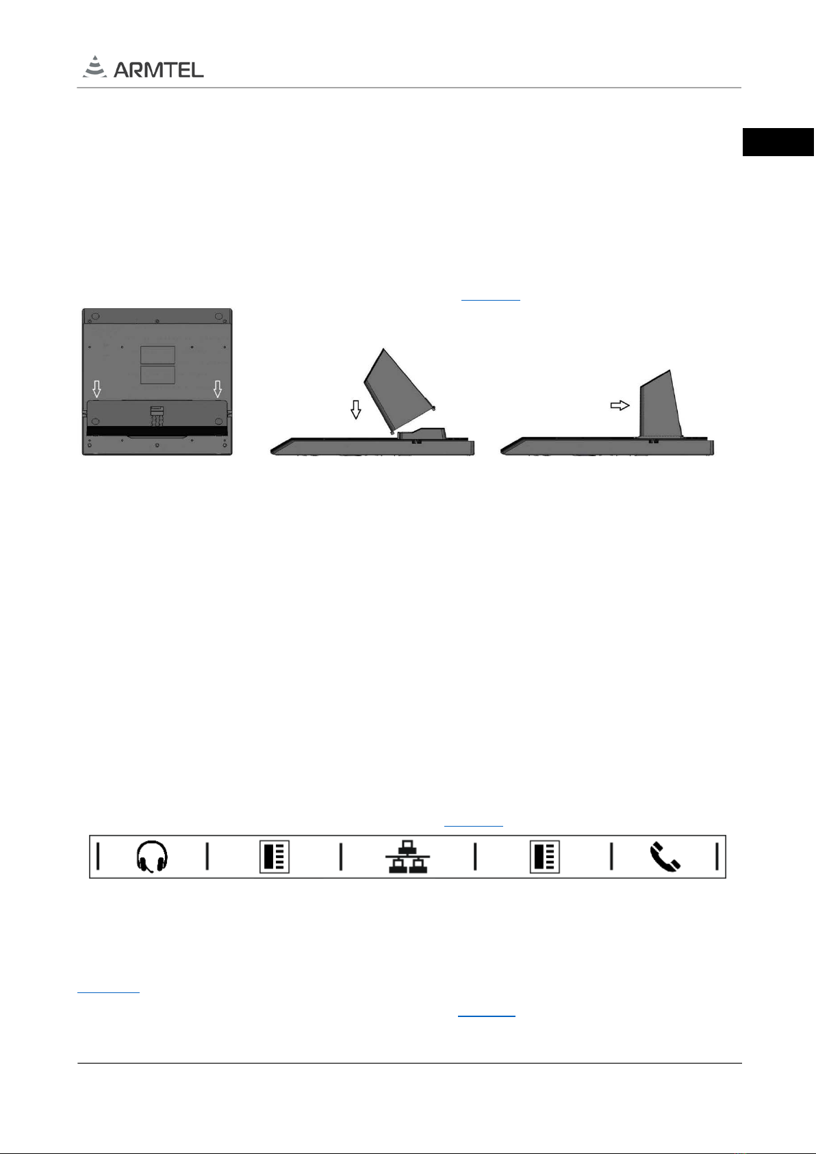
To impart stability, the stand is equipped with rubber protruding legs. When desk-
mounted, to adjust the stand in desktop version, see Figure 3:
a)
b)
c)
Figure 3 – Adjustment of the stand for Desktop
To adjust the stand:
a) turn the unit upside down disconnecting it from the power supply and
interfaces, pull out four plugs from the grooves to install the stand and
simultaneously press the two latches at the base of the stand;
b) insert the stand stoppers in the far-end grooves in the bottom of the enclosure;
c) push the stand into the near-end grooves.
Remove the stand in the reverse order.
1.1.5.3 A plate with the designation of sockets for external connections located on
the base of the enclosure is shown in illustrated at Figure 4.
Figure 4 – The plate with the designation of sockets for external connections
1.1.5.4 To ensure a reliable connection of DTS-TOP cables, they can be placed in special
grooves in the base of the enclosure (4 pcs.) and in the stand (2 pcs.) in accordance with
Figure 5. When DTS-TOP is supplied to the customer, the grooves in the base of the
enclosure are closed with special plugs (not shown in Figure 5), which must be removed from
the grooves before the cables are laid.
ENG

DTS-ТОР MULTIFUNCTIONAL TELEPHONE
User Manual
page 12/51 armtel.com
1 – grooves in the stand; 2 – grooves in the base of the enclosure.
Figure 5 – Grooves for laying of communication cables
As a headset (not included into the scope of supply) of any model and manufacturer
with the following parameters can be used:
– microphone type – electret;
– microphone sensitivity – at least 30 db;
– speaker impedance – in the range of from 32 to 300 Ohm;
– frequency range of headphones – at least 100-16000 Hz;
– connection: RJ-11 4P4C.
1
2
ENG

DTS-ТОР MULTIFUNCTIONAL TELEPHONE
User Manual
armtel.com page 13/51
info@armtel.com © Armtel
1.1.6 LABELING
On the bottom side of DTS-TOP casing is placed bilingual nameplate.
The nameplate contains the following information:
−name, trademark and reference information of the manufacturer;
−product name and description;
−permissible operating temperature range;
−degree of protection provided by enclosures (IP code);
−rated supply voltage value;
−electrical class III mark according GOST IEC 61140-2012;
−commercialization mark for products on the market of Customs Union member
states;
−special waste disposal mark;
−product serial number;
−date of manufacture.
The serial number and MAC address are unique for each product.
ENG

DTS-ТОР MULTIFUNCTIONAL TELEPHONE
User Manual
page 14/51 armtel.com
1.1.7 PACKAGE
The DTS-TOP with the assembly kit and documents, which come with the supply
package, is packed in consumer package (cardboard box).
Before packing in consumer package (cardboard box), DTS-TOP with the assembly kit
and operational documentations are placed in plastic film covers that have the
corresponding marking. DTS-TOP is additionally exposed to temporary anticorrosion
protection with technical silica gel.
A label in Russian language and English language is glued onto the consumer package,
said label containing the following inscriptions and symbols:
−product name and description;
−name, trademark and reference information of the manufacturer;
−handling symbols according to GOST 14192-96 and CU TR 005/2011;
−commercialization mark for products on the market of Customs Union member
states;
−serial number and date of manufacture.
The package is made according to the drawings of the product manufacturer and
enables storage of the DTS-TOP, provided requirements set in Section 5 are met.
For shipment of the DTS-TOP from the manufacturer, consumer package contents are
placed in the package place, which ensures protection from mechanical damage, direct
ingress of atmospheric precipitation, dust and solar radiation during transportation.
ENG
DTS-ТОР MULTIFUNCTIONAL TELEPHONE
User Manual
armtel.com page 15/51
info@armtel.com © Armtel
1.2 DESCRIPTION AND OPERATION OF THE PRODUCT COMPONENTS
1.2.1 GENERAL INFORMATION
The main components of DTS-TOP are as follows:
−DTS-TOP main board;
−functional keys;
−microphone;
−speaker;
−Display.
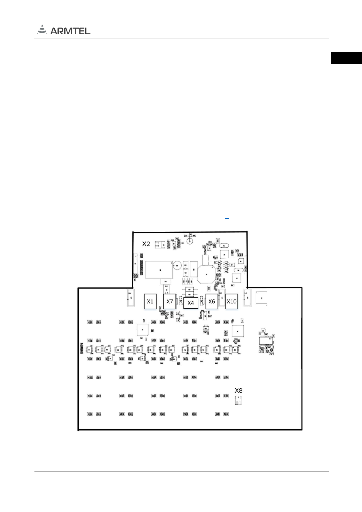
1.2.2 MAIN BOARD
DTS-TOP main board is a printed board with installed electronic elements required for
functioning of the DTS-TOP.
External appearance of main board is given on Figure 6.
Figure 6 – DTS-TOP main board
ENG

DTS-ТОР MULTIFUNCTIONAL TELEPHONE
User Manual
page 16/51 armtel.com
The main controller of the board is comprised of two ATMEGA128A-AU
microcontrollers with a 10-bit ADC and 128 Kbytes of programmable memory. When the
power and interface are connected, the main board ensures DTS-TOP functioning with
respect to the algorithm allotted by DCN-2 central exchange. The main board of DTS-TOP
has sockets; some of them are lead out to the base of the enclosure for connection with Uko
network interface, headset and handset and with EC-TOP (see Figure 6):
-Х1 – socket for connection of a headset;
-Х2 – socket for connection of integrated speaker;
-Х8 – socket for connection of integrated microphone;
-Х6, Х7 – sockets for connection of EC-TOP expansion units;
-Х4 – socket for connection of power supply and Uko interface cables;
-Х10 – socket for connection of a handset.
On the board there are LEDs backlighting for the desktop keys including contact
pads for each key, the closing of which, when you press the keys, leads to the execution of
a specific function assigned to DTS-TOP key.
1.2.3 KEYS
The keys with LED illumination are arranged in five pieces in a row, the number of
rows is six. The keys are equipped with a silicone membrane to ensure DTS-TOP protection
degree. Each key consists of a transparent cap, pusher and a base. When the key is pressed,
the conductive base closes the contact pads on the main board.
Conditionally, the keys can be divided into three functional blocks: the keys of the
keypad, function keys and direct call keys.
Location of DTS-ТОР keys is illustrated at Figure 7.
ENG

DTS-ТОР MULTIFUNCTIONAL TELEPHONE
User Manual
armtel.com page 17/51
info@armtel.com © Armtel
«1», «2», «3», «4», «5», «6», «7», «8», «9», «*», «0», «#» – keypad;
«+», «-» – volume control of integrated speaker, handset and
headset speakers; – call replay; – turn on
speakerphone mode; «F1…F4» – function keys; «DK1…DK10» –
direct call keys.
Figure 7 – Location of DTS-TOP keys
Using keypad keys, you can dial the phone number of the called party. The function
keys are used to increase or decrease the volume of the phone integrated speaker, handset
and headset speakers, ringer, display brightness, call repeat, hands-free mode and menu
navigation. At the time of pressing, each key of the keypad and the function key is highlighted
by green LED.
For any direct call key «DK1…DK10» the functions of establishing connection with
subscribers or local functions can be fixed from the DCN-2 exchange (for example, the
"Headset" that switches the "Handsfree" and "Headset" modes or functions of volume
control of the integrated speaker and the handset and headset speakers).
There are two ways of processing keystrokes programmatically. In one case, pressing
is treated as closing the contact, releasing the key - as an opening. Otherwise, the closure of
the circuit is remembered after the key is released, and the second pressing of the key is
treated as an opening. The methods for processing keystrokes are set from the DCN-2
exchanger.
The transparent cap of each key is backlighted by LEDs located below the keys on
the main board. Depending on the programmed function of a particular key, different
backlight colors are available – red, green, blue and orange.
Types of LED indication of the phone when implementing various programmed
functions are given in 4.3.
Keys have increased mechanical strength and durability.
In DTS-TOP, the keypad keys and function keys are equipped with the necessary labels
at the manufacturer assembly.
The direct call keys have no labels, and the transparent film included in scope of supply
for DTS-TOP can be used to indicate the functionality of the key. Functional inscriptions are printed
on a printer capable of printing on a material up to 100 microns thick and placed under
transparent caps of the key. It is allowed to print the inscriptions using an A4 paper sheet. Key
label template for printing the function of the target keys is given in Appendix D.
For convenience of placing functional labels, the slot on the key cap end is provided
(see Figure 8). To throw the cap open, then insert a cap film or paper element prepared in
accordance with the template (Appendix D) with the printed function label inside the cap, and
then latch the cap back.
ENG

DTS-ТОР MULTIFUNCTIONAL TELEPHONE
User Manual
page 18/51 armtel.com
a) a slot
b) to open the cap of the key upwards
Figure 8 – The way of opening of the key cap
1.2.4 HADSET
In DTS-TOP, a handset is used, consisting of a body, a dynamic telephone capsule and a
microphone. Inside the body there is permanent magnet, which, when the handset is removed, opens
the reed switch located under the cover, thereby turning-on the handset. The high-resistance
telephone capsule provides a range of reproducible frequencies from 300 to 3400 Hz. The handset
has a highly sensitive circular microphone with a range of perceived frequencies from 100 Hz to 10
kHz.
1.2.5 SPEAKER
DTS-TOP uses a wideband 2,5 Inch broadband speaker with plastic membrane, main
specifications are as follows: rated resistance 8 Ohm, frequency range from 200 to 15kHz is used
in DTS-TOP.
1.2.6 DISPLAY
To display additional information and for user convenience, DTS-TOP uses TFT
graphic display with LED backlights, with 4.3” diagonal, the resolution of 480*272 pixels that
ensures clear visibility of displayed data. The anti-reflective coating improves perceiving of
information displayed, it is applicable for bright lighting conditions as well.
Display indicates DTS-TOP number in the network, current date and time, functions
performed when keypress, types of established communication during incoming and
outgoing calls, numbers of called and calling subscribers.
ENG
This manual suits for next models
1
Table of contents
Other ARMTEL Telephone manuals


 user manual")


