ARMTEL ARMT.665230.006UM User manual

DWEx Digital Loud-Speaking
Explosion Proof Call Station
ARMT.665230.006UM
User Manual
Document version 19
26.30.23.000
2022

armtel.com
© Armtel info@armtel.com

DWEX DIGITAL LOUD-SPEAKING EXPLOSION PROOF CALL STATION
User Manual
armtel.com page 1/40
info@armtel.com © Armtel
INTRODUCTION
This User Manual is intended for introducing «DWEx Digital Loud-Speaking Explosion
Proof Call Station» ARMT.665230.006, including versions ARMT.665230.006-01…
ARMT.665230.006-33 (Table 1), manufactured by Armtel LLC, Russia to the User.
Table 1 – Variants of DW (beginning)
Identification Name
ARMT.665230.006 DWEx for 2 connections with 25W Amplifier
ARMT.665230.006-01 DWEx for 4 connections with 25W Amplifier
ARMT.665230.006-02 DWEx for 6 connections with 25W Amplifier
ARMT.665230.006-03 DWEx for 8 connections with 25W Amplifier
ARMT.665230.006-04 DWEx for 16 connections with 25W Amplifier
ARMT.665230.006-05 DWEx for 24 connections with 25W Amplifier
ARMT.665230.006-06
DWEx for 2 connections with handset, dial pad and
25W Amplifier
ARMT.665230.006-07
DWEx for 8 connections with handset, dial pad and
25W Amplifier
ARMT.665230.006-08 DWEx with handset, dial pad and 25W Amplifier
ARMT.665230.006-09 DWEx for 10 connections with 25W Amplifier
ARMT.665230.006-10 DWEx for 18 connections with 25W Amplifier
ARMT.665230.006-11 DWEx for 12 connections with 25W Amplifier
ARMT.665230.006-12
DWEx for 2 connections with dial pad and 25W
Amplifier
ARMT.665230.006-13
DWEx for 4 connections with dial pad and 25W
Amplifier
ARMT.665230.006-14
DWEx for 8 connections with dial pad and 25W
Amplifier
ARMT.665230.006-15
DWEx for 10 connections with dial pad and
25W Amplifier
ARMT.665230.006-16
DWEx for 16 connections with dial pad and
25W Amplifier

DWEX DIGITAL LOUD-SPEAKING EXPLOSION PROOF CALL STATION
User Manual
page 2/40 armtel.com
Table 1 – Variants of DW (end)
Identification Name
ARMT.665230.006-17 DWEx for 2 connections
ARMT.665230.006-18 DWEx for 4 connections
ARMT.665230.006-19 DWEx for 6 connections
ARMT.665230.006-20 DWEx for 8 connections
ARMT.665230.006-21 DWEx for 16 connections
ARMT.665230.006-22 DWEx for 24 connections
ARMT.665230.006-23 DWEx for 2 connections with handset and dial pad
ARMT.665230.006-24 DWEx for 8 connections with handset and dial pad
ARMT.665230.006-25 DWEx with handset and dial pad
ARMT.665230.006-26 DWEx for 10 connections
ARMT.665230.006-27 DWEx for 18 connections
ARMT.665230.006-28 DWEx for 12 connections
ARMT.665230.006-29 DWEx for 2 connections and with dial pad
ARMT.665230.006-30 DWEx for 4 connections and with dial pad
ARMT.665230.006-31 DWEx for 8 connections and with dial pad
ARMT.665230.006-32 DWEx for 10 connections and with dial pad
ARMT.665230.006-33 DWEx for 16 connections and with dial pad
DWEx is the subscriber equipment to use at industrial and transportation enterprises
within digital Intercom and Public Address /General Alarm (PA/GA) communication systems
DCN and IPN manufactured by Armtel, Russia.
Short name of product – DWEx.

DWEX DIGITAL LOUD-SPEAKING EXPLOSION PROOF CALL STATION
User Manual
armtel.com page 3/40
info@armtel.com © Armtel
DWEx is designed for employment in explosion proof zones of the premisses and
external installations in accordance with certain explosion proof marking, requirements
GOST IEC 60079-14-2013, chapter 7.3 «Regulations for Electrical Installation» (PUE),
ATEX 2014/34/EU and other normative documents, regulating usage of electrical equipment
in highly explosive zone.
DWEx has explosion-proof categories: «explosion-proof equipment», provides
protection type of «flameproof enclosure» («d») according EN 60079-1:2014, provides
protection «increased safety «е» according EN 60079-7:2015, provides protection
«intrinsically-safe circuit «i» type «ib» according EN 60079-11:2012, provides protection type
of «dust ignition protection type «t» according EN 60079-31:2014 and designed according
EN 60079-0:2012.
Explosion-proof marking as per EN 60079-0:2012 – «II 2 G Ex db eb ib IIC T6 Gb» and
«II 2 D Ex tb IIIC T85°C Db IP66».
Maintenance personnel for DWEx shall be appointed by the management at the
installation site.
The maintenance personnel shall be required to know the operating procedure of
DWEx to the extent provided for by the User Manual.
Duties of the maintenance personnel shall include maintenance of DWEx in accordance
with this User Manual.
ATTENTION! In connection with systematic work to improve the design and
manufacturing technology, it is possible some discrepancy between the description and the
supplied product, which does not affect its operation or maintenance.
DWEX DIGITAL LOUD-SPEAKING EXPLOSION PROOF CALL STATION
User Manual
page 4/40 armtel.com
SAFETY PROVISIONS
During installation and operation of DWEx, observe safety precautions laid out in local
regulations on electrical safety.
To avoid electric shock, do not:
−operate the product with a damaged power or communication cable;
−the interface cable can be connected and disconnected if the power cable is
disconnected.
WARNING: DO NOT OPEN WHEN ENERGIZED.
ATTENTION!VARIANT OF DWEX WITH 25W AMPLIFIER IS NOT DESIGNED FOR
“PHANTOM” POWER SUPPLY
In order to ensure fire safety, follow the following rules:
−before connecting the product to the power supply, make sure the power and
communication cables are properly insulated;
−protect power and communication cables from damage.
The safety provisions for specific operations described in this manual are marked with:

DWEX DIGITAL LOUD-SPEAKING EXPLOSION PROOF CALL STATION
User Manual
armtel.com page 5/40
info@armtel.com © Armtel
CONTENTS
INTRODUCTION.................................................................................................................................................................... 1
SAFETY PROVISIONS........................................................................................................................................................... 4
CONTENTS .............................................................................................................................................................................. 5
1 DESCRIPTION AND OPERATION................................................................................................................................. 7
1.1 Features....................................................................................................................................................................... 7
1.2 Main specifications ...............................................................................................................................................10
1.3 Scope of supply......................................................................................................................................................12
1.4 Design........................................................................................................................................................................13
1.5 Explosion-proof......................................................................................................................................................18
2 INTENDED USE ................................................................................................................................................................20
2.1 Operating limits .....................................................................................................................................................20
2.2 Explosion-proof operation.................................................................................................................................20
2.3 Safety precautions.................................................................................................................................................21
2.4 Preparation for use ...............................................................................................................................................22
2.5 Installation, connection and dismantling .....................................................................................................23
2.5.1 Explosion protection during installation .............................................................................................23
2.5.2 Installation DWEx .........................................................................................................................................24
2.5.3 Connection of DWEx unit..........................................................................................................................26
2.5.4 Dismantling ....................................................................................................................................................27
2.6 Operation .................................................................................................................................................................28
2.6.1 Configuration.................................................................................................................................................28
2.6.2 Product operating modes.........................................................................................................................28
2.6.3 Procedure for monitoring the operability of the product............................................................30
2.6.4 Troubleshooting...........................................................................................................................................31
3 MAINTENANCE................................................................................................................................................................32
3.1 General guidelines ................................................................................................................................................32
3.2 Safety precautions.................................................................................................................................................32
3.3 Maintenance procedure......................................................................................................................................32
4 SHELF AND SERVICE LIFE, DISPOSAL......................................................................................................................33
4.1 Repair.........................................................................................................................................................................33

DWEX DIGITAL LOUD-SPEAKING EXPLOSION PROOF CALL STATION
User Manual
page 6/40 armtel.com
4.2 Storage......................................................................................................................................................................33
4.3 Transportation ........................................................................................................................................................33
4.4 Disposal.....................................................................................................................................................................33
APPENDIX А(reference) External appearance of DWEx ......................................................................................34
APPENDIX B (reference) Connection DWEx..............................................................................................................36

DWEX DIGITAL LOUD-SPEAKING EXPLOSION PROOF CALL STATION
User Manual
armtel.com page 7/40
info@armtel.com © Armtel
1 DESCRIPTION AND OPERATION
1.1 Features
DWEx digital explosion-proof call station is the subscriber equipment of Public Address
and General Alarm system completed with DCN/ IPN central exchange (manufactured by
Armtel, Russia).
DWEx according explosion-proof marking «II 2 G Ex db eb ib IIC T6 Gb» and
«II 2 D Ex tb IIIC T85°C Db IP66» (EN 60079-0:2012) can be used in potentially explosive gas
environments, except for mines and the relevant surface facilities exposed to firedamp explosive
atmospheres.
DWEx equipment can be used at sites of steel, chemical, oil and gas processing
industries, including metal and woodworking areas, other similar sites where standard
PA/GA equipment is not applicable.
DWEx has different versions with regard to the modules installed.
External appearance all versions of DWEx are given in Appendix A.
DWEx can operate only under control of the central exchange of the communication
systems DCN or subscriber module IPN-8U, and it is unable to perform any functions without
connection to the communication system via the digital Uk0-interface.
DWEx can only work under the control of the central switch of the DCN communication
system or the IPN-8U subscriber module, and cannot perform any functions without
connecting to the communication system via the digital Ukointerface.
As part of the DCN system built on the basis of the Ukₒ interface, DWEx can provide
the following functions:
–Loudspeaker simplex communication by means of the main or remote
microphones and the main or external loudspeaker;
–Simplex and duplex communication by means of a telephone handset;
–Outgoing communication with a group of subscribers;
–Incoming communication as part of a group of subscribers;
–Launch and broadcast of alarms, alerts and other pre-recorded messages for single
subscribers and a group of subscribers;
–Receiving alarms, alerts and other pre-recorded messages from other
subscribers, both individually and as part of a group;

DWEX DIGITAL LOUD-SPEAKING EXPLOSION PROOF CALL STATION
User Manual
page 8/40 armtel.com
–Indications of the direction of the call, the status of terminal devices on the call
buttons of these devices (incoming and outgoing communication,
unavailability);
–Maintaining a system of call priorities;
–Connecting an external speaker via an additional amplifier;
–Control of an external light signaling device (lamp) using a built-in relay;
–Adjust the volume level of the main speaker, the handset speaker and the
external speaker;
–Microphone sensitivity adjustments.
As part of the IPN system, when connected to IPN-8U, DWEx provides the following
functions:
−establishing a connection with other terminal subscriber IP devices of the IPN
system using target keys/buttons (CC) with indication of the status of
programmed functions, telephone keypad (keyboard) or external microphone
tangent;
−Loudspeaker simplex communication by means of the main or remote
microphones and the main or external loudspeaker;
−Simplex and duplex communication by means of a telephone handset;
−Outgoing communication with a group of subscribers;
−Incoming communication as part of a group of subscribers;
−Launch and broadcast of alarms, alerts and other pre-recorded messages for single
subscribers and a group of subscribers;
−Receiving alarms, alerts and other pre-recorded messages from other
subscribers, both individually and as part of a group;
−Indications of the direction of the call, the status of terminal devices on the call
buttons of these devices (incoming and outgoing communication,
unavailability);
−Maintaining a system of call priorities;
−Connecting an external speaker via an additional amplifier;
−Control of an external light signaling device (lamp) using a built-in relay;

DWEX DIGITAL LOUD-SPEAKING EXPLOSION PROOF CALL STATION
User Manual
armtel.com page 9/40
info@armtel.com © Armtel
−Adjust the volume level of the main speaker, the handset speaker and the
external speaker;
−Microphone sensitivity adjustments.
The complete structure of DWEx functions performed, their implementation and
configuration features may differ depending on the type of the communication system, its
configuration and software version. DWEx programming is executed using the DCN, IPN or
system administrator's software. Description of the features of DWEx application in the
systems IPN 1.1 and DCN, as well as programming techniques are given in the operational
documentation for these systems.
DWEX DIGITAL LOUD-SPEAKING EXPLOSION PROOF CALL STATION
User Manual
page 10/40 armtel.com
1.2 Main specifications
Main specifications are provided in Table 2.
Table 2 – Main specifications of DWEx (beginning)
Parameters Value
Rated voltage, V 48
Supply voltage range, В from 36 to 60
Quiescent current under rated voltage, maximum, mА25
Number of programmable direct connections/functions from 2 to 24
Maximum operating current without auxiliary amplifier, maximum, мА 95
Maximum operating current with auxiliary amplifier, maximum, А1,1
Maximum constant power (external (signal) device circuit), W 60
Maximum switching voltage (external (signal) device circuit), V 60
Maximum switching current DC (external (signal) device circuit ), A 2,0
Maximum power for main amplifier power, maximum W 1,0
Speech bandwidth, Hz
from 300 to
6800
Sound pressure level of built-in loudspeaker at the maximum volume, dB 95
Explosion-proof marking as per EN 60079-0:2012
«II 2 G Ex db eb ib
IIC T6 Gb»
«II 2 D Ex tb IIIC
T85°C Db IP66»

DWEX DIGITAL LOUD-SPEAKING EXPLOSION PROOF CALL STATION
User Manual
armtel.com page 11/40
info@armtel.com © Armtel
Table 2 – Main specifications of DWEx (end)
Parameters Value
Electric protection class as per GOST 12.2.007.0-75, IEC 61140 II
Protection degree provided by shells (under GOST 14254-2015
(IEC 60529:2013)) (IP-code)
IP66
Climatic category according GOST 15150-69
NF11)
Ambient temperature range, ºC
from -40 to +70
Air pressure range, kPa
from 84 to
106,7
Relative humidity, at the temperature of 25 °С, % Up to 100
Line interface Ua/Ub DWEx
Uk
0
-interface,
according CCITT
Transfer protocol «Armtel»
Overall dimensions, mm
refer Figure 1
Weight (depending on the version), kg
from 8,5 to 9,1
1) Outdoor use
The design and material of the DWEx housing have impact and chemical resistance,
resistant to solar ultraviolet radiation. The coating is resistant to ultraviolet radiation, oil and
gas resistance, and resistant to the effects of chemical environment specified in Table 3.

DWEX DIGITAL LOUD-SPEAKING EXPLOSION PROOF CALL STATION
User Manual
page 12/40 armtel.com
Table 3 – Resistance of the coating to chemical media
Сhemical environment Resistance
Dilute mineral acids, 3% solution resistant
Acetic acid, diluted, 3% solution resistant
Alkalis, 50% solution
resistant
Ammonia, 10% aqueous solution
resistant
Alcohols resistant
1.3 Scope of supply
Scope of supply of DWEx is given in Table 4.
Table 4 – Scope of supply
Identification Name
Quanty-
ty, pcs.
Note
ARMT.665230.006*
DWEx Digital Loud-Speaking Explosion
Proof Call Station
1
Installation kit
RMLT.734311.002
Bracket
2
Screw М6×16 DIN 933
4
Washer 6 DIN 127
4
Washer 6 DIN 9021
4
Operational documentation
ARMT.665230.006PP
Product Passport
1
ARMT.665230.006UM
User Manual
1
* Version according to the contract for the supply
DWEX DIGITAL LOUD-SPEAKING EXPLOSION PROOF CALL STATION
User Manual
armtel.com page 13/40
info@armtel.com © Armtel
1.4 Design
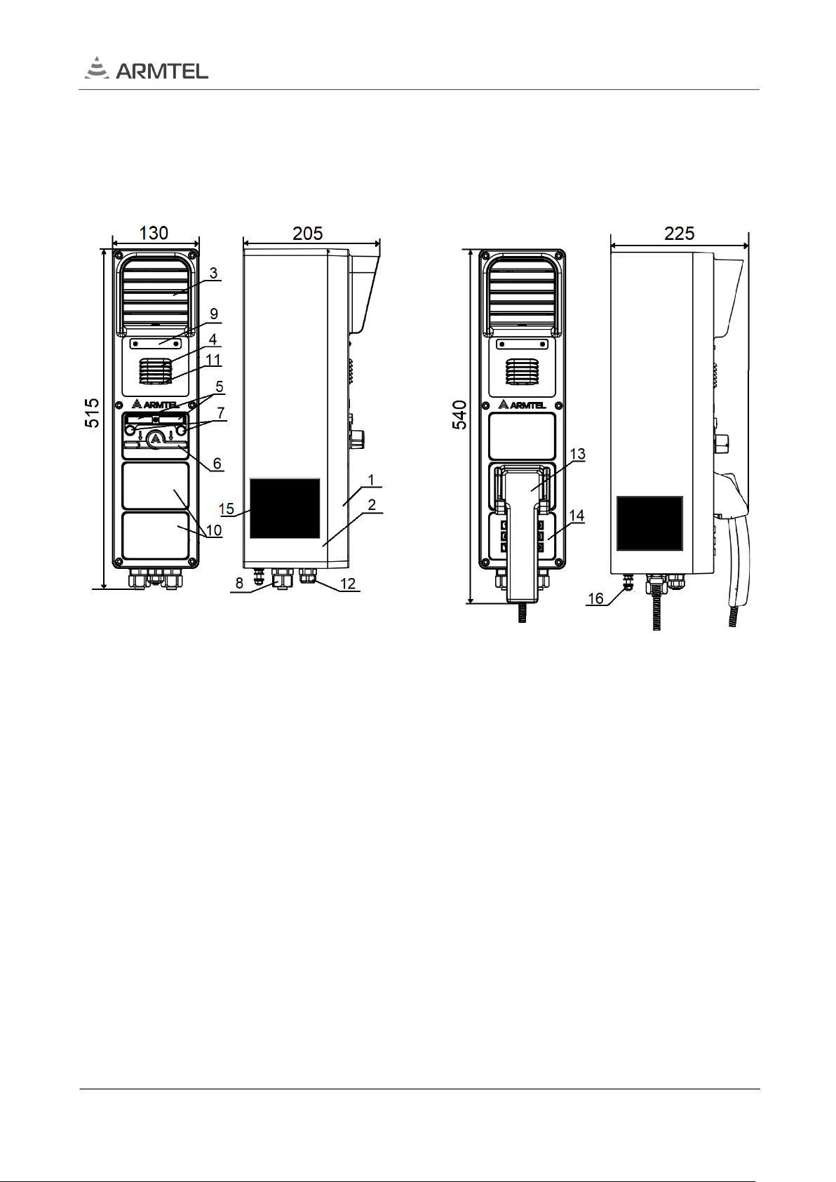
DWEx overall dimensions are shown on Figure 1.
The color of the case coating is orange, RAL2004.
a) excluding versions
ARMT.665230.006-06…-08 and-23…-25
b) versions
ARMT.665230.006-06…-08 and -23…-25
1 – cover; 2 – enclosure; 3 – speaker; 4 – microphone; 5 – marking nameplate for two-way
toggle; 6 – two-way toggle; 7 – LEDs for mode indication; 8 – cable glands for cables 9-17
mm dia; 9 – marking panel; 10 – plug; 11 – LEDs for DWEx indication; 12 – cable glands
for cables 7 - 13 mm dia; 13 – handset; 14 – dial pad; 15 – nameplate; 16 – functional
earthing clip
Figure 1 – Overall dimensions DWEx
In front, the cover (2) is fitted to the enclosure (1). The cover is fixed to DW enclosure
by six screws. At the top of the cover there is an integrated loudspeaker (3), under which
there is a nameplate (9) for placing a label with the designation of the subscriber in the
communication network. A microphone (4) is located under the nameplate. Speaker and the
microphone are protected from mechanical damage and direct contact with small particles
and water by the shaped grills of the enclosure cover. In lower part of the DWEx cover,
depending on the version, from one to three two-way toggle modules (6) are installed.

DWEX DIGITAL LOUD-SPEAKING EXPLOSION PROOF CALL STATION
User Manual
page 14/40 armtel.com
Above the two-way toggles there are LEDs (7) indicating the operation modes and
nameplates (5) for placing exchangeable labels, indicating the programmed functions
performed by DWEx in these positions of the two-way toggles. Instead of missing two-way
toggle modules / dial pad / button modules / handset, plugs (10) are installed.
Information on the manufacturer, marking, warning notes and main parameters of the
product are given in the nameplate (15).
Cables for connection of DWEx unit are input through the sealing cable glands type
8161/7 М25×1,5 (8) with outer cable diameter from 9 to 17 mm and 8161/7 М20×1,5 (12)
with outer cable diameter from 7 до 13 mm.
The DW-BC board is fixed by supports on inside of the cover The board has the
following components (see Figure 2):
Figure 2 – External appearance of DW-BC board
The board has the following components:
1, 3, 6 – sockets «X1», «X2» and «X3» for two-way toggle, pushbuttons and dial pad
(see back side of the board);
2, 4, 10 – («SW6», «SW5», «SW4») - two-positions DIP-switches for the type of installed
modules in the corresponding cover compartments. The correspondence of the switch
positions and the installed modules is shown in Table 5, where "x" is the DIP-switch number.

DWEX DIGITAL LOUD-SPEAKING EXPLOSION PROOF CALL STATION
User Manual
armtel.com page 15/40
info@armtel.com © Armtel
Table 5 – DIP-switch positions
SWx.1 SWx.2 Type of installed module
OFF OFF
Plug or dial pad (keypad
module)
ON OFF
Two-way toggles for two
connections (including
buttons «SOS», «INFO»)
OFF ON
Pushbuttons (8 direct keys
module)
ON ON
Handset and a cradle
hermetic sensor
5 – «R18» – volume control of the main amplifier (VOLUME INT) – not used;
7 – «R26» microphone handset sensitivity control (MIC HS);
8 – «R15» built-in microphone sensitivity control (MIC INT);
9 – «R22» external microphone sensitivity control (MIC EXT) – not used;
11 – technological socket «XP1» for programming the board;
12 – switch «SW2» to select the type of microphone caps used in the remote
microphone:
1) in the ON position – electret microphone (remote with tangent);
2) in the OFF position, there is no dynamic microphone or microphone.
13 – socket «X5» for external microphone with tangent;
14 – switch «SW1» to select the type of microphone caps used in the front panel:
1) in the ON position – electret microphone (built-in);
2) in the OFF position, there is no dynamic microphone or microphone.
15 – socket «X8» for built-in speaker;
16 – socket «X4» for built-in microphone;
17 – switch «SW3» to select the type of microphone caps used in the handset:
1) in the ON position – electret microphone (tube);
2) in the OFF position, there is no dynamic microphone or microphone.

DWEX DIGITAL LOUD-SPEAKING EXPLOSION PROOF CALL STATION
User Manual
page 16/40 armtel.com
18 – socket «X7» for connect to main board;
19 – «R17» volume control of an external loudspeaker (VOLUME EXT);
20 – «SW8» – a two-position switch for setting the sensitivity of a microphone amplifier
with AGC, common to all microphones. The correspondence of the position of the switches
and the sensitivity of the AGC is shown in Table 6.
Table 6 – Microphone sensitivity selection
SW8.1 SW8.2 Microphone sensitivity
OFF OFF Max
ON OFF Medium
OFF ON Low
ON
ON
Min
21, 22 – socket «X12» (X12 = X12 (button) + X15 (indication)) for button module
«INFO» – not used;
23, 24 – socket «X13» (X13 = X13 (button) + X16 (indication)) for button module
«SOS» – not used
25 – socket «X6» for handset;
26 – socket «X9» for bracket with reed relay.
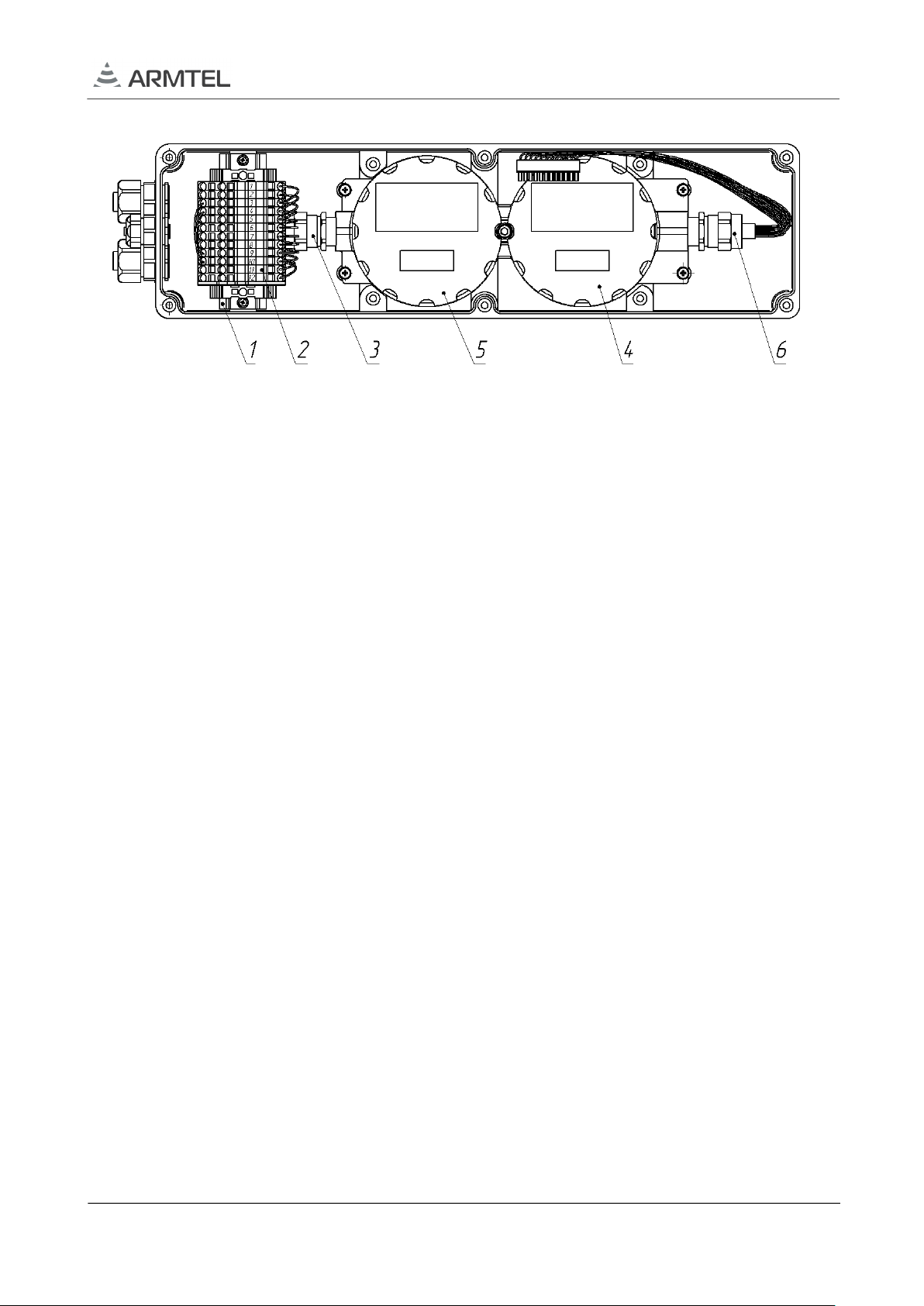
Inside the DWEx enclosure (see Figure 3), an explosion-proof box DKV-3.1
manufactured by "Armtel" LLC is fixed on the posts. In the lower part of the DKV-3.1 box
there is an additional amplifier (5), in the upper part of the box there is a block of main
boards (4). The explosion-proof DKV-3.1 box with the main boards block and the additional
amplifier is connected to the terminal box (2) and to the DW-BC board from the cover (using
the intrinsically safe cable).
DWEX DIGITAL LOUD-SPEAKING EXPLOSION PROOF CALL STATION
User Manual
armtel.com page 17/40
info@armtel.com © Armtel
1 – DIN rail; 2 – terminal block; 3 – Ex-cable gland for external connections;
4 – place of block of main boards; 5 – place of additional amplifier; 6 - Ex-cable gland
with intrinsically safe cable
Figure 3 – DWEx enclosure with an explosion proof box
The electromechanical relay installed in the main boards block of DWEx unit inside
the explosion proof box DKV-3.1 («d»-type shell), is designed for switching with incoming
calls to external devices, such as a light signal device (not included in the scope of supply).
The operating mode of the relay coincides with the operating mode of the auxiliary amplifier
and is determined by its configuration parameters. The following modes of the relay
operation are available:
–the relay is not activated during a call;
–the relay is always activated when an incoming call comes in (default mode);
–the relay is activated when the first call comes in, and is turned off after the
subscriber answers. Re-enable after the lock interval of 15 seconds.
he main boards block and the KIB board are connected between each other and
the terminal box by electric cables, which ensure their interaction and functioning in
the communication system.
Auxiliary amplifier 25 W is installed in versions DWEx (see Table 1). The auxiliary
amplifier is installed inside the explosion proof box DKB-3 with a «d»-type shell (see
Figure 4), which is connected to the terminal box and the KIB board
The following operation modes are available for the auxiliary amplifier:
–OFF;
–ON, messages are playbacked concurrently with the main amplifier;
–The auxiliary amplifier is used for the voice call.

DWEX DIGITAL LOUD-SPEAKING EXPLOSION PROOF CALL STATION
User Manual
page 18/40 armtel.com
In the latter case, the incoming message is broadcast simultaneously by the integrated
and auxiliary amplifiers, but only before pressing of DWEx key to respond the call. After
the response, the auxiliary amplifier is turned off, and the calls are only broadcast to the
integrated amplifier. It is turned on again after a predetermined interval after the end of the
communication session (usually 15 seconds).
The operating mode and the output delay value for the auxiliary amplifier are specified
in the unit configuration data using the communication system administration software. The
volume control of the auxiliary amplifier is on the KIB board (see Figure 3).
To ensure the protection degree IP66 DWEx unit in compliance with requirements of
standards GOST 14254-2015 (standards – DIN VED 0470 Pat1, EN60529:1991/А2:2013, IEC
529), sealing rubber and silicone gaskets are placed under the cover, speaker and
microphone, switch mechanisms and cable glands.
1.5 Explosion-proof
1.5.1 Compliance with the requirements of ATEX 2014/34/EU to meet the requirement
of interstate and national standards.
1.5.2 Explosion protection type "e" in DWEx is provided by:
–Compliance with the requirements of EN 60079-7:2015 for electrical installation
leakages and electrical gaps;
–Temperature limits on the surface of the enclosure, the cover and on electrical
contacts to a maximum level of not more than +85 °C according to group T6 to
EN 60079-0: 2012;
–Use of Ex-components in the equipment, such as explosion-proof cable glands
series 8161 manufactured by STAHL and explosion-proof terminal blocks
STS 2.5 TWIN manufactured by Phoenix Contact.
1.5.3 Explosion protection type "d" in DWEx is provided by putting its electrical
circuits in an explosion-proof shell made in accordance with EN 60079-1:2014.
Explosion-proof box DKV-3.1 made of aluminum alloy is used as the shell. The cable
outlet from the explosion-proof box is made through Ex-cable gland marked Ex d IIC
During the manufacturing process, the explosion-proof box DKV-3.1 is tested for
explosion resistance in accordance with EN 60079-1:2014 with the pressure 1.5 times higher
than the pressure of the explosion.
Wiring is carried out by a cable of 0.5 mm2cross-section for each core and with
reinforced insulation, which withstands the test voltage of 3000 V AC without breakdown.
The tightness of the connection and the compliance with the requirements of explosion
Table of contents
Other ARMTEL Telephone manuals


