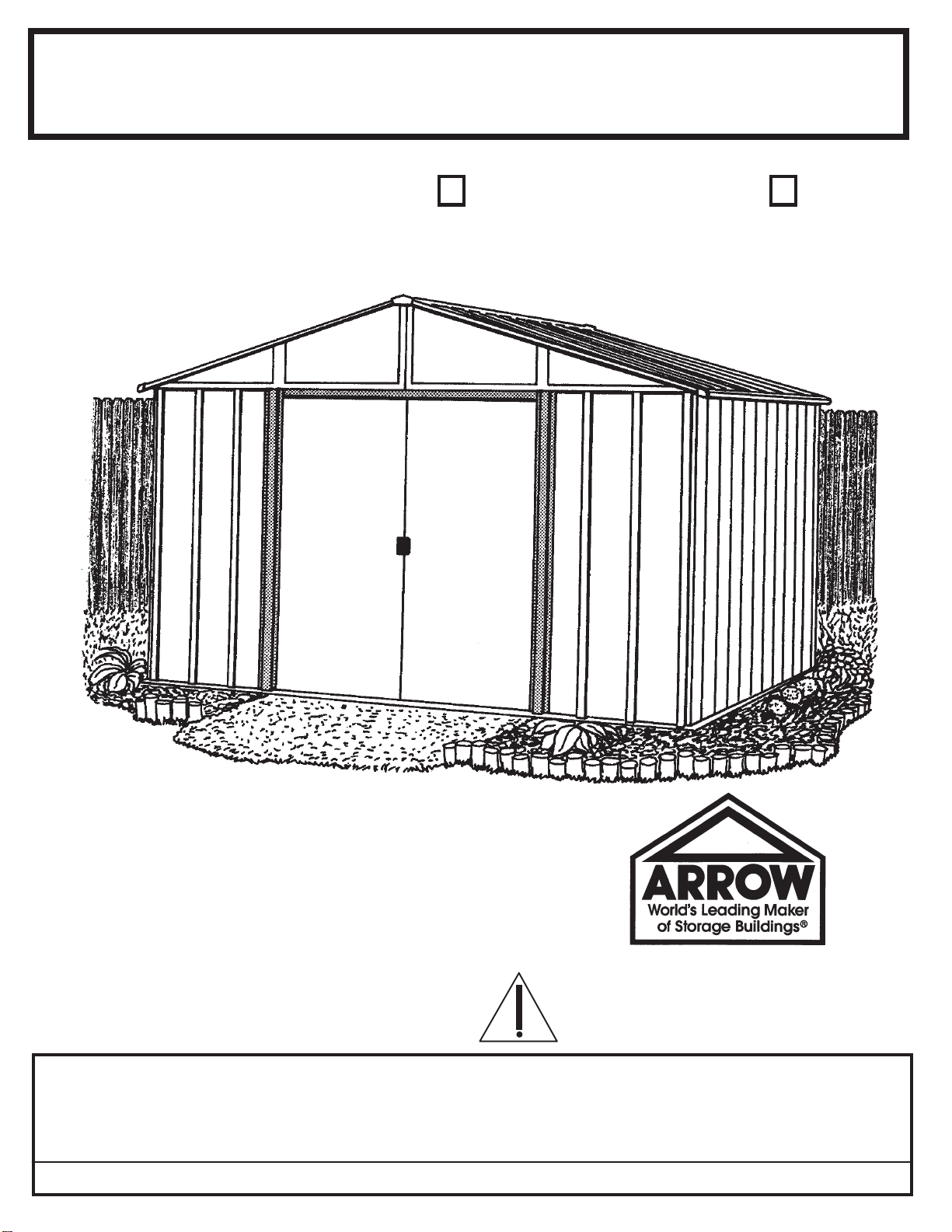
Arrow AR1012-B Use and care manual
Other Arrow Outdoor Storage manuals
Arrow
Arrow GS83C Use and care manual
Arrow
Arrow HM10867 Use and care manual
Arrow
Arrow HM101267-A1 Use and care manual
Arrow
Arrow RH1014-C1 Use and care manual
Arrow
Arrow CO1014-C1 Use and care manual
Arrow
Arrow ED1012-B1 Series Use and care manual
Arrow
Arrow CLG1012CC Instructions for use
Arrow
Arrow CL72-A Use and care manual
Arrow
Arrow YT108M Series Use and care manual
Arrow
Arrow VD86 Series Use and care manual
Arrow
Arrow NP10867 Instructions for use
Arrow
Arrow SG1014FB Series Use and care manual
Arrow
Arrow HM8667 Use and care manual
Arrow
Arrow FDN477 Use and care manual
Arrow
Arrow LW108LM Instructions for use
Arrow
Arrow ED1012 B1 Use and care manual
Arrow
Arrow CLG108CC Instructions for use
Arrow
Arrow EZEE SHED EZ10872HVCR Instructions for use
Arrow
Arrow EH86-A Use and care manual
Arrow
Arrow SBS64 Instructions for use
Popular Outdoor Storage manuals by other brands


Lifetime
Lifetime 6418 owner's manual

rollaway container
rollaway container ARPCA24 manual

Duratuf
Duratuf Havelock Assembly instructions

X-METAL
X-METAL 4065 owner's manual

Outdoor Life Products
Outdoor Life Products FP2030 F Assembly instructions

Royalcraft
Royalcraft Faro 295L Storage Box Assembly instructions