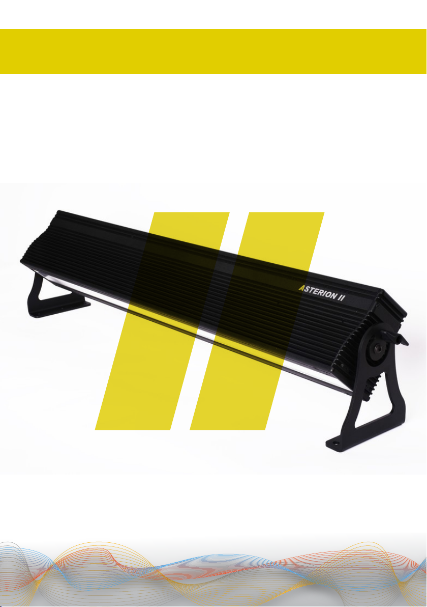
ASTERION II / USER MANUAL / ENGLISH
5
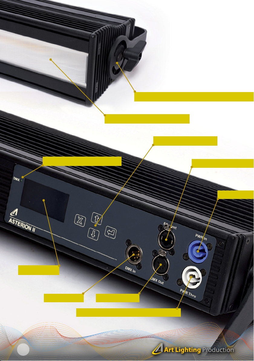
DESCRIPTION OF THE PRODUCT 01
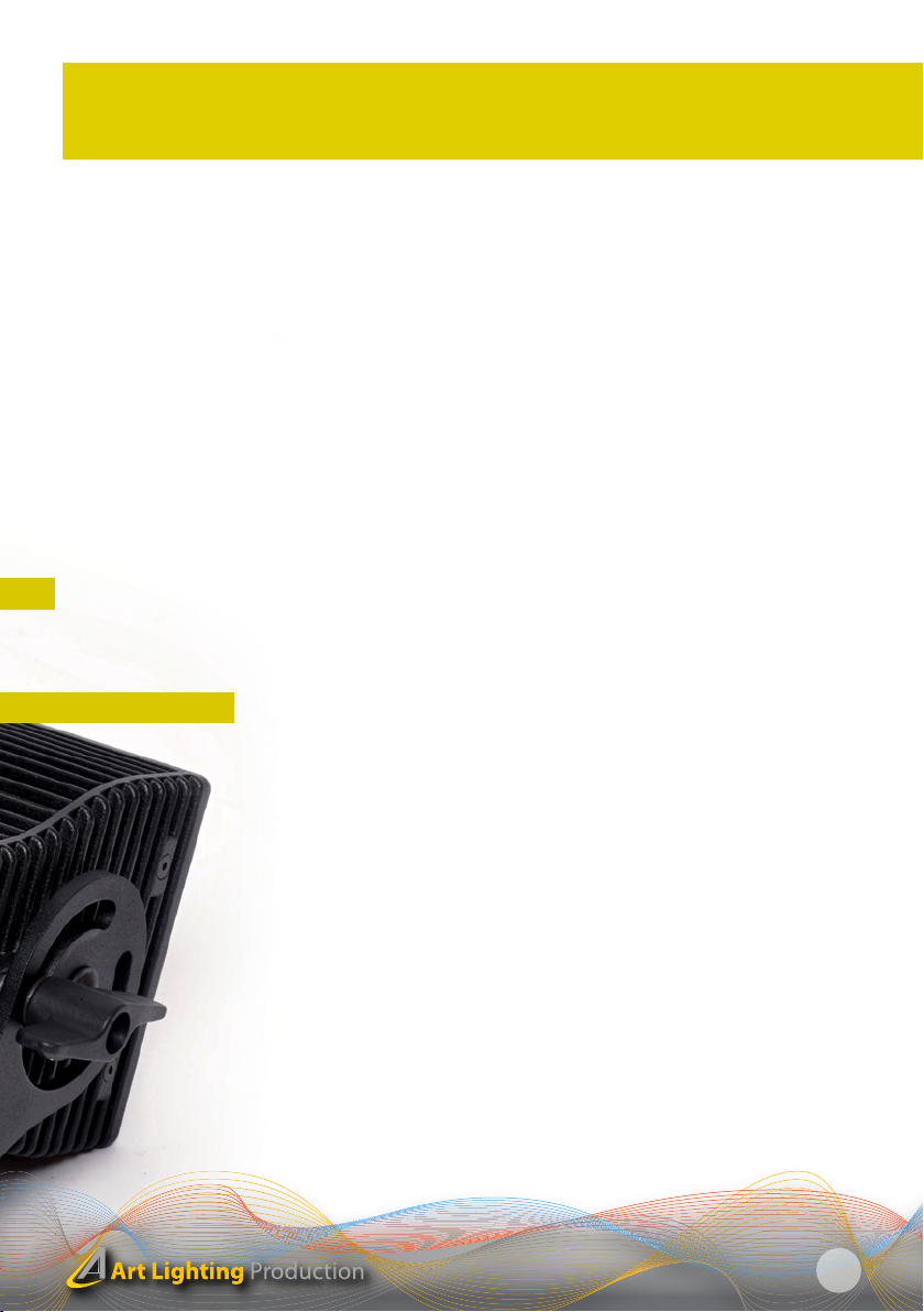
1. Disc / flange for installing fastening elements - the arresting disc
of the luminaire, which is always its part, is used for installing the fasten-
ing elements. The fastening elements can be selected by the customer
and are not part of the basic delivery. You may select the individual fas-
tening elements in the chapter II. Optional accessories. All elements for
assembly of the optional accessories are part of it.
2. Protecting light diffusion plate - The protecting light diffusion plate
is always part of the basic delivery!
3. Powercon input for power supply 230V - The power supply of the
luminaire is made with a special cable with Powercon terminal on one
side and Schuko plug connector on the other. The Powercon connector
must be, after inserting in the luminaire, turned around until its locking.
For disconnecting of the power supply cable the slider of the safety lock
must be moved away from the luminaire and then you can turn the con-
nector and pull it out.
4. Powercon output for power supply 230V - If you want to connect
several floodlight battens then you shall use Powercon interconnecting
cable The Powercon is designed for a load of 10A. You shall not connect
in series more than 8 ASTERION luminaires!
5. DMX INPUT / 6. DMX OUTPUT.
7. ETHERNET - Fixture control through the sACN and ArtNet*.
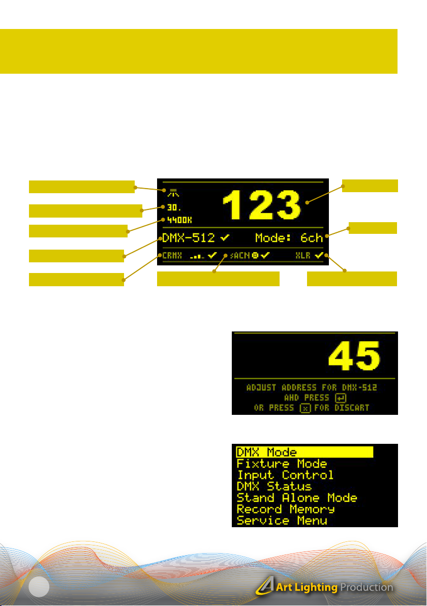
8. OLED display - Modern oLED display shows clearly all activated fea-
tures on the main screen. After a selectable time of inactivity when set-
ting up, the display turns itself off. This setting is used to ensure that the
illuminated display do not disturb the viewers. By pressing any button
the display lights up again. The automatic switching off function of the
display can be turned off.
9. - 12. Control buttons - 9. Button CANCELLATION - RETURN / 10. But-
ton UP / 11. Button DOWN / 12. Button for confirmation ENTER
13. DMX - LINK indicator light - If the indicator light is lit, the DMX signal
should be okay. If the indicator light is not lighting then the DMX signal is
not correct or the signal is interrupted.
* Only in the case of the model ASTERION II NET
1. Disc / flange for installing fastening elements
3. Powercon input for power supply 230V
7. ETHERNET (sACN, ArtNet)*