Art Project Series User manual
USBMIX6
SIX CHANNEL MIXER WITH
USB INTERFACE AND DSP EFFECTS
Project Series
User’s Manual

1
IMPORTANT SAFETY INSTRUCTIONS - READ FIRST
This symbol, wherever it appears, This symbol, wherever it appears, alerts you
alerts you to the presence of uninsulated to important operating and maintenance
dangerous voltages inside the enclosure that instructions in the accompanying literature.
may be sufficient to constitute a risk of shock. Please read the manual.
Read instructions
Retain these safety and operating instructions for future reference. Heed all warnings printed here and on the
equipment. Follow the operating instructions printed in this user guide.
Do not open
There are no user serviceable parts inside. Refer any service work to qualified technical personnel only.
Power sources
Only connect the unit to mains power of the type described in this user guide or marked on the rear panel. The
power source must provide a good ground connection.
Power supply
Use the external power supply for your local mains supply as provided with the equipment. If the provided
external supply does not fit into you outlet consult your service agent. Route the external power cord so that it
is not likely to be walked on, stretched or pinched by items placed upon or against.
Grounding
Do not defeat the grounding and polarization means of the power cord plug. Do not remove or tamper with the
ground connection on the power cord.
Moisture
To reduce the risk of fire or electrical shock, do not expose the unit to rain, moisture or use in damp or wet
conditions. Do not place container of liquid on it, which may spill into any openings
Heat
Do not locate the unit in a place close to excessive heat or direct sunlight, as this could be a fire hazard.
Locate the unit away from any equipment, which produces heat such as: power supplies, power amplifiers and
heaters.
Environment
Protect from excessive dirt, dust, heat, and vibration when operating and storing. Avoid tobacco ash, drink
spillage and smoke especially that associated with smoke machines.
Handling
Protect the controls from damage during transit. Use adequate padding if you need to ship the unit. To avoid
injury to yourself or damage to the equipment take care when lifting, moving or carrying the unit.
Servicing
Switch off the equipment and unplug the power cord immediately if it is exposed to moisture, spilled liquid or
the power cord or plug becomes damaged during a lightning storm or if smoke odor or noise is noted. Refer
servicing to qualified technical personnel only.
Installation
Install the unit in accordance with the instruction printed in the user manual.

2
INTRODUCTION
The ART USBMIX6 Microphone, Instrument, and Line Mixer / Computer Interface is a compact versatile
audio interface for your computer that converts analog signals from a variety of audio sources to a
digital audio. The built-in low latency stereo digital effects add to the versatility. It can also be used as
a stand-alone mixer through the main mix outputs. The USBMIX6 provides a great starting point for
personal home studio recording or for anyone wanting to do mobile location recording. Use the
USBMIX6 to record pod casts, capture your latest idea for a song, make voiceovers for your home
movies, or record a jam with a friend - whenever and wherever your creativity takes you!
Features
Powered by a 5vdc external power supply, USB interface needed when used with a computer
CH1 and 2 Microphone (balanced XLR) inputs or instrument (unbalanced ¼-inch TS) inputs with
switchable impedances
Switchable low noise +48V phantom power for microphones
Balance ¼-inch TRS inputs for stereo or mono line-level sources on CH3-4
¼-inch TRS output jacks work with balanced or unbalanced lines
Unbalanced RCA inputs Ch5-6
Stereo ¼-inch TRS headphone jack with independent level control for output monitoring
Independent controls for both sets of inputs, main output, and headphone monitor
Red LED signal/clip indicator for Ch1-2, overall gain shown on LED meter display
Switchable assignment of USB playback to channels 5 and 6 or monitor
No special drivers needed with most modern versions of Windows, Mac OS, and Linux
USB cable, USB power adaptor and Audacity recording software included
Rugged steel case

3
INSTALLATION
This compact audio mixer with USB interface and DSP effect unit is suitable for universal applications,
e.g. for audio recording with a the computer. It has four input channels, i.e. 2 x mono, 2 x stereo, for
connecting microphones (also phantom-powered) and other audio sources with line signal level ( e.g.
musical instruments, players). In addition, there are connections for recording and headphones are
provided. The mixed stereo signal is sent via ¼-inch jacks and the USB jack. The USB jack can be
used at the same time as an input for transferring audio data from the computer to the mixer.
The power connection is made via the supplied AC power adapter.
Prior to powering up the unit, the output controls MONITOR PHONES and MAIN MIX should be turned
back to “0”.
1. As audio sources, microphones and/or audio sources with line signal level (e.g., effect units, musical
instruments, players) can be connected to the four input channels.
Mono channels CH1 and CH2:
Combo XLR/¼-inch jacks are available as inputs.
Connect microphones to the balanced XLR jack.
For phantom-powered microphones it is possible to activate a 48V phantom power for both XLR
jacks together with switch PHANOM POWER. When activated (switch positionⅠ= on) the indication
PHANTOM PWR +48V lights up during operation.
Caution! Do not connect a microphone with unbalanced output via XLR plug; it may be
damaged by the phantom power. To prevent switching noise, only activate or deactivate the
phantom power.
Connect mono sources with line level to the unbalanced ¼-inch jacks. It is also possible to directly
connect musical instruments with high impedance (electric guitar, electric bass) to these jacks: in
this case engage the impedance switch for that channel.
Stereo channels CH3/4 and CH5/6:
Stereo sources with line level may be connected to the ¼-inch jacks of channel CH3/4 and to the
RCA jacks of channel CH5/6 (L=left channel, R= right channel). The jacks of channel CH3/4 are
balanced; however, it is also possible to connect units with an unbalanced output. For connecting a
mono unit to channel CH3/4, use the Left jack only: Then the mono signal is internally sent to the
right channel and the left channel.

4
2. The RCA jacks Aux can be used for connection of a stereo recording device.
3. Connect the replay output of the stereo recording device to the input AUX IN;
4. Connect the recording input of the recording device to the output AUX OUT; the output receives the
sum signal adjusted with the control MASTER MIX
5. However, the connections may also be used for other units with line signal level, e.g., like a CD or
MP3 player may be connected to AUX IN or an amplifier to AUX OUT.
6. Connect stereo headphones (impedance ≥8 OHM) to the ¼-inch jack MONITOR PHONES.
7. The sum of the signals are adjusted with the control MAIN MIX, the audio is present at the stereo
output MAIN MIX OUT.
8. Here e.g., an amplifier or a second mixer may be connected. The ¼-inch jacks are unbalanced
9. For power supply, connect the power adapter provided to the jack 5VDC and to a mains outlet
(115VAC or 230VAC).
10.Note: If the mixer is not used for a long period of time, then disconnect the power adapter from the
socket. Even when the mixer is switched off, the power supply unit has low power consumption.
11.To switch on the mixer, set the POWER switch to position “ON”. The power indication POWER ON
lights up.

5
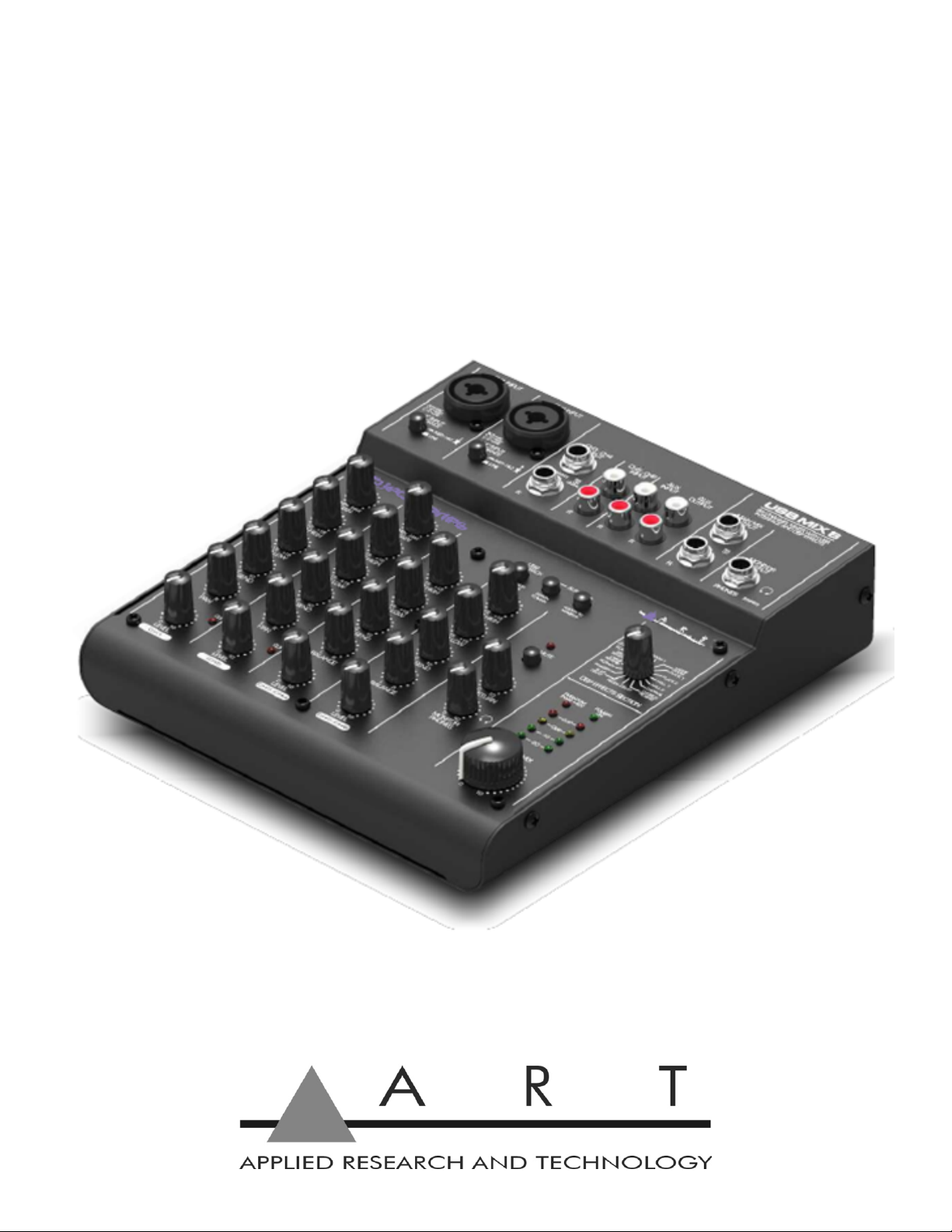
CONTROLS AND INDICATORS

6
Phantom Power Switch (+48 V) for the XLR jack of channels CH 1 and CH 2.
Power Mains switch of the mixer.
Power supply jack It is used for connecting the power supply adapter, provided.
USB jack (type B) for the connection to a computer: it can be used both as an audio output (output of
the sum signal) and as an audio input (feed-thru audio data for reproduction via channel CH 5/6).
Combo Input (combined jack XLR, balanced / ¼-inch jack unbalanced) for channel CH 1 and channel
CH 2, for connection of a microphone via an XLR plug or an audio source with line signal level via a ¼-
inch jack.
Instrument/Line Impedance switch, for channel CH 1 and channel CH 2: engage the switch when an
electric guitar or an electric bass with passive audio pick-up has been connected to the ¼-inch jack.
Stereo Input (¼-inch jack, bal.) for channel CH3/4 for connection of an audio source with line signal
level; when connection a mono source, use the Left jack only.
Stereo Input (RCA) for channel CH5/6 for connection of an audio source with line signal level.
Aux Output (RCA) from the mixer to a Stereo Input.
Aux Input (RCA) from the mixer to a Stereo Output.
Main Mix Out (¼-inch jack, unbalanced) for a connection of an amplifier or another unit, e.g. a second
mixer.
Phones Monitor Output (¼-inch jack) for connection of stereo headphones (minimum impedance
8Ohm) for monitoring the sum signal independent of the master control or the signal at the input Aux
In.

7
USB Playback Switch assigns signal of USB jack to channels CH5/6 or to MONITOR PHONES.
Assign to Main Used to switch the input signal of the input AUX INPUT to the Main Mix output.
Assign to Monitor Used to switch the input signal of the input AUX INPUT to the headphone output.
GAIN Control to adjust the input amplification, for channel CH 1 and channel CH 2.
Channel Equalization Equalizer to adjust the high frequencies ( EQ HI ) and low frequencies (EQ LO),
for each input channel.
Effect Control For each input channel, to adjust the effect component for each channel.
Pan Control For channel CH1 and CH2, to place the mono signal in the stereo field.
Balance Control For channel CH3/4 and CH 5/6.
Clip LED Level peak indication, for channel CH1 and CH2.
Level Control For each input channel.
FX Mute Switch, when the button switch engaged, the internal effect processor is muted at its output,
and the LED will light up.
FX Return Control to add the effect signal to the sum signal.
Phones Monitor Controls the level for the headphones output.
DSP Effects Control pot switches to select the effects.
Phantom Power +48V Indicator, this lights when the Phantom Power switch is set to ON for CH1 and
CH2.
Power On Green indicator LED is illuminated when the mixer is powered up.
Stereo level indicator LED’s, the sum signal adjusted with the master control; in case of overload the
CLIP LED’s light up.
Main Mix Control sets the level of the output signal sent via the outputs MAIN MIX, AUX OUTPUT and
the USB port.

8
OPERATION WITH A COMPUTER
When operating the mixer with a computer, either use the audio software supplied with the operating
system or audio software installed additionally. Various programs for audio reproduction/ recording are
available on the Internet free of charge.
1. Boot up the computer and connect the USB jack to a USB port at the computer via the USB cable
provided. The USB interface of the mixer is recognized by the computer as an external unit for audio
input and audio output, depending on the operating system e.g., as “USB Audio CODEC”. The
required drivers (standard drivers of the operating system) are available on the computer.
2. Note: If not all drivers required are available on the computer, install them, e.g., via the original CD
of the operating system. If necessary, restart the computer after installation.
3. Activate the audio program used and make the necessary adjustments for the audio reproduction
via the mixer or audio recording from the mixer.
If no audio recording or audio reproduction is possible, check in the system settings of the computer if
the USB interface has been selected for the audio input or audio output.
Hint: If the mixer is connected both to a computer and to any equipment, which have earth ground
mains cables (e.g. amplifiers), ground loops may occur due to hum interference. To eliminate this, the
mixer should be connected to the respective equipment via a ground isolator.
USB COMPUTER SETTINGS
Once the USB connection is made and your computer is on, your computer will power the USB
interfaces circuitry over the USB bus and the unit will automatically connect and try to set your computer
“Default Audio Device” to be “USB Audio CODEC”. Usually, the computer will do this automatically
whenever a USB device is first connected, but it is sometimes necessary to make the selection
manually. The same settings may need to be made in your particular audio application as well (Check
your application instructions). These settings should be made while the USBMIX6 and computer are
connected and powered on.
Your computer audio output “Speaker” is now set to be the “USB Audio CODEC” and playback audio
is routed to the USBMIX6. This must be done while the USBMIX6 is connected to the computer and
powered on. If you prefer, you can have the computer output routed to your computer speakers instead
of the USBMIX6 monitor output jack, by selecting your computer speakers for “OUTPUT” instead of
“USB Audio CODEC” in the above setup procedures. After the above settings are made, your computer
will automatically reconfigure itself back to these settings every time the USBMIX6 is reconnected to
the computer. Your recording software may also select which inputs or outputs are being used.
Note: The USBMIX6 interface uses the standard “USB Audio CODEC”. This driver is built into most
modern operating systems, including most current versions of Linux. Since some details of how the
audio interface is set vary with different versions of Linux, the setup is beyond the scope of this
document. The main key in setup is to look for “USB Audio CODEC” as the recording source or playback
monitor output while the USBMIX6 is connected.
APPLICATIONS
The following basic steps serve as an aid for a general setup.
1. As a basic setting first

9
a. set all control GAIN, EQ, PAN /BAL to mid-position.
b. Turn all control LEVEL back to "0".
2. To adjust a mono channel to an optimum level, feed an audio signal to the channel and turn up its
control LEVEL approximately to mid-position. Adjust the control GAIN of the channel so that the 0
dB LED's of the level indication shortly light up at passages of highest volume. Then adjust the
sound with the controls EQ: High for the high frequencies, Low for low the bass frequencies. As the
sound adjustments affect the channel level, readjust the gain adjustment, if necessary. Then turn
the control LEVEL back to the stop and make the same adjustments for the second mono channel.
3. For the sound adjustment of a stereo channel turn the controls LEVEL of the remaining channels
back to the stop and turn up the control LEVEL of the respective stereo channel so that the sound
can be adjusted in an optimum way with the equalizer controls
4. When all adjustments for level matching and all sound adjustments have been made, mix the signals
of the input channels in the desired volume ratio with the LEVEL controls. The CLIP LED's of the
mono channels should not flicker at all or only flicker shortly at signal peaks. If they light up
continuously attenuate the volume of the channel. Always turn the LEVEL controls of the channels
not used back to the left stop.
5. For the mono channels place the mono signals in the stereo sound with the PAN controls and adjust
the stereo balance for the stereo channel with the Balance controls.

10
6. To switch the signal of the input AUX IN, e.g. reproductions of MP3's or CD, to the sum signal, press
the button ASSIGN TO MAIN. To feed the AUX IN signal only to the sum, turn the LEVEL controls
of the input channels back to the stop.
Note: If a recording made via the output AUX OUT is reproduced via the input AUX IN at the same
time, the button ASSIGN TO MAIN must not be pressed otherwise feedback will occur.
7. Adjust the desired overall volume with the control MASTER. Then observe the level indication. In
general, an optimum control is obtained at 0dB. However, if the output level of the mixer is too high
for the following unit, the sum signal must be adjusted to correspond to the lower level. If the red
overload LED's CLIP light up, turn back the master control and / or individual channel level controls
accordingly.
Adding an effect
1. Turn up the effects level control FX RETURN approximately to mid-position so that the following
effect adjustments can be heard.
2. Select one of 16 effects available with the rotary switch DSP EFFECT SECTION.
DSP Effects: Position 1. Is at 12 O'clock, rotating the pot clockwise.
1. ROOM 1 9. REGEN/DELAY
2. LARGE ROOM 10. SLAP/DELAY
3. PLATE1 11. PHASER
4. PLATE2 12. ROTARY
5. HALL1 13. LARGE REVERB
6. HALL2 14. GATED REVERB
7. CHORUS 15. FLANGER
8. CHORUS/REVERB 16. DOUBLING
3. Adjust the desired effect component for each channel with the controls FX SEND.
4. Add the effect signal in the desired intensity to the signal sum with the effect level control FX
RETURN.

11
WARRANTY INFORMATION
Limited Warranty
Applied Research and Technology will provide warranty and service for this unit in accordance with the
following warrants:
Applied Research and Technology, (ART) warrants to the original purchaser that this product and the
components thereof will be free from defects in workmanship and materials for a period of three years
from the date of purchase. Applied Research and Technology will, without charge, repair or replace, at
its option, defective product or component parts upon prepaid delivery to the factory service department
or authorized service center, accompanied by proof of purchase date in the form of a valid sales receipt.
Exclusions
This warranty does not apply in the event of misuse or abuse of the product or as a result of
unauthorized alterations or repairs. This warranty is void if the serial number is altered, defaced, or
removed.
ART reserves the right to make changes in design or make additions to or improvements upon this
product without any obligation to install the same on products previously manufactured.
ART shall not be liable for any consequential damages, including without limitation damages resulting
from loss of use. Some states do not allow limitations of incidental or consequential damages, so the
above limitation or exclusion may not apply to you. This warranty gives you specific rights and you may
have other rights, which vary, from state to state.
For units purchased outside the United States, an authorized distributor of Applied Research and
Technology will provide service.

12
SERVICE
The following information is provided in the unlikely event that your unit requires service.
1. Be sure that the unit is the cause of the problem. Check to make sure the unit has power, all cables
are connected correctly, and the cables themselves are in working condition. You may want to
consult with your dealer for assistance in troubleshooting or testing your particular configuration.
2. If you believe that the ART unit is at fault, go to www.artproaudio.com.
3. Select “Support”, then “Return Authorization Request” to request a return authorization number.
4. If you are returning the unit for service, pack the unit in its original carton or a reasonable substitute.
The original packaging may not be suitable as a shipping carton, so consider putting the packaged
unit in another box for shipping. Print the RA number clearly on the outside of the shipping box. Print
your return shipping address on the outside of the box.
5. Include, with your unit, a note with the RA number and your contact information, including a return
shipping address (we cannot ship to a P.O. box) and a daytime phone number, and a description of
the problem, preferably attached to the top of the unit. Also include a copy of your purchase receipt.
Please fill in the following information for your reference:
Date of purchase: ___________________________________________
Purchased from: ___________________________________________
Serial Number ___________________________________________

13
SPECIFICATIONS
Input Connections XLR balanced / ¼-inch unbalanced “Combo” jack (Ch1&2 inputs)
¼-inch balanced or unbalanced (Ch3-Ch4 inputs)
RCA unbalanced (Ch5-Ch6)
RCA Aux loop In Left and Right
Output Connections ¼-inch TRS balanced (Main Mix outputs)
¼-inch TRS stereo (Monitor output)
RCA Aux loop Out Left and Right
Input Impedance 240k Ohms (Inst-HiZ), 20k Ohms (Line) (Ch1-Ch2, Ch3-Ch4 ¼-inch inputs)
(Ch5-Ch6 RCA inputs)
>4k Ohms (Ch1-Ch2 XLR input)
Output Impedance <1k Ohms (balanced¼-inch), <500 Ohms (unbalanced ¼-inch)
<500 Ohms (unbalanced RCA)
100 Ohms (Monitor output)
Frequency Response 20 Hz – 20 kHz (+0, -1 dB)
THD <0.01% @ 1 kHz
CMRR >60dB typical
Phase Response All connections are phase coherent
Signal to Noise Ratio >90dB typical (Ref 0dBu)
Equivalent Input Noise 120dBu typical (XLR bal, max gain), -125dBu typical (¼-inch & RCA)
Maximum Input Level +4dBu (XLR input), +20dBu (¼-inch input), 18dBu (RCA)
Maximum Output Level +15dBu (Main Mix, AUX outputs), +15dBu (Monitor)
Maximum Gain
(In to Main Out) +54dB (XLR), +39dB (¼-inch) (CH1&CH2)
+10dB (¼-inch) (Ch3-Ch4)
+11dB (RCA) (Ch5-Ch6)
(In to USB) +44dB (XLR), +30dB (¼-inch unbalanced) (CH1&CH2)
+0dB (¼-inch) (Ch3-Ch4)
+6dB (RCA) (Ch5-Ch6)
+8dB (RCA) (AUX IN L&R)
(USB to Out) +14dB (Main Mix), +14dB (Monitor)
Phantom Power selectable, +48V DC, filtered, current limited
A/D-D/A 16 Bit, 44.1 kHz or 48 kHz, USB selectable from computer
0.4 ms A/D latency @44.1 kHz
Computer Interface USB Class compliant plug-and-play Mac and PC interface
Chassis Type All steel black finish
Power Requirements 5v DC @ <1A (external) (Adaptor Included)
Dimensions (HWD) 1.9” x 7.4” x 8.5”
47mm x 186mm x 215mm
Weight 2.75 lbs. (1.25 kg) with power supply and USB cable
Note: 0 dBu = 0.775Vrms
ART maintains a policy of constant product improvement. Therefore, specifications are subject to change without notice.
Go to www.artproaudio.com for the latest information and support.

Other manuals for Project Series
6
This manual suits for next models
1
Table of contents


