Artel FiberLink Beamer-V User manual

WWW.ARTEL.COM
MANUAL
Fiber optic transmission of composite
video in a simple, low-cost system
Installation and Operations
Manual
FiberLink
Beamer-V™

Page 2 FiberLink Beamer-V™ User’s Manual
FiberLink Beamer-V™
Contents
Welcome .................................................................3
Features ..................................................................3
Package Contents.........................................................3
Technical Specications
Video Specications..................................................4
General Specications................................................4
Certications.........................................................4
Installation Instructions ...................................................4
Interface Troubleshooting .................................................6
Warning ..................................................................6
CE Information............................................................6
Contents

Page 3FiberLink Beamer-V™ User’s Manual
FiberLink Beamer-V™
Welcome
Thank you for purchasing Artel Video Systems’ FiberLink Beamer-V Composite Video over
Fiber Series. Beamer-V is a high-quality, cost-eective ber optic video transmission system
designed to transmit color and black and white signals over distances of more than a mile.
The system is easily installed and designed for long, troublefree operation in most indoor or
outdoor-protected environments. Beamer-V is compatible with all analog video standards,
including NTSC, PAL and SECAM, and will operate with all standard 62.5 micron ber optic
cables and industry standard ST type connectors.
Features
• Transmits up to three kilometers over multimode ber at 850 nm
• May be purchased as a complete, low cost system including transmitter, receiver and
two power supplies
• Card version supports dual video channels
• Card version lls one slot in 6000A card cage
• Fiber is immune to the eects of electrical interference, ground loops, explosive and
hazardous environments, moisture and high voltage
Package Contents
If you purchased part number 3100 or 3101, your product is supplied with:
• 1 Beamer-V Transmitter or Receiver unit
• This User’s Manual
If you purchased part number 3105, your product is supplied with:
• 1 Beamer-V Transmitter unit
• 1 Beamer-V Receiver unit
• 2 12 Vdc Power Supplies
• This User’s Manual
Welcome | Features | Package Contents

Page 4 FiberLink Beamer-V™ User’s Manual
FiberLink Beamer-V™ Technical Specications/Installation Instructions
General Specications
Number of Fibers Box: 1; Card: 2 (1 per channel)
Operating Temperature -35 to +75oC
Relative Humidity 10 to 90%, non-condensing
Operating Power (per unit) 9-12 V +10% DC @ 100 ma max.
Dimensions 3.25 L x 2.38 W x 1 H (inches)
83 L x 60 W x 25.4 (mm)
Weight 3.0 oz. (85.04 grams)
Optical Connectors ST
Optical Wavelength 850 nm
Optical Fiber 62.5 micron multimode ber
Video Specications
Number of Channels 1
Number of Outputs per Channel Box: 1; Card: 2
Bandwidth 8 MHz
Input/Output Impedance 75 Ohms
Signal-to-Noise Ratio (per RS-250) 52 dB minimum
Dierential Gain (per RS-250) 2% typical
Dierential Phase (per RS-250) 1otypical
Input/Output Voltage 1 volt p-p
(user adjustable at receiver)
Certications
Installation Instructions
See the diagram on the following page for assistance during installation. Please note
that Beamer-V Box units (transmitter P/N 3100 and receiver P/N 3101) may be used in
conjunction with 2-channel card versions of Beamer-V (transmitter P/N 3108A and receiver
P/N 3109A). If you are connecting one or more box units to a card unit, please refer to the
manual that came with your card unit for installation instructions regarding that portion of
your system.

Page 5FiberLink Beamer-V™ User’s Manual
FiberLink Beamer-V™
The following instructions describe the typical installation procedure:
1. Mount the Beamer-V transmitter at the camera or source of video to be transmitted.
Use the mounting tabs on the housing or the enclosed selfadhesive mounting pad.
2. Connect one of the plug-in power supplies to the input connector on the Beamer-V
transmitter. If an external power source is to be used, be certain it provides regulated
12 volts DC+10%. Current from this source will not exceed 250 ma. When power is
applied, the red PWR indicator LED will glow. Note that the (-) side of the power input
is connected to the enclosure.
3. On the Beamer-V transmitter, connect the video signal to be transmitted to the BNC
connector and the ST ber optic cable plug to the optical connector.
4. Mount the Beamer-V receiver at the monitor or device where the video will be
received.
5. Connect the remaining plug-in power supply to the Beamer-V receiver’s input
connector. If an external power source is to be used, be certain it provides regulated
12 volts DC +10%. Current from this source will not exceed 250 ma. When power is
applied, the red PWR indicator LED will glow. Note that the (-) side of the power input
is connected to the enclosure.
6. Connect the video monitor or other video receiving device to the BNC connector
on the Beamer-V’s receiver and the ber optic cable plug to the Beamer-V receiver’s
optical connector.
7. For a pleasing picture, slowly adjust the LEVEL control on the Beamer-V’s receiver. If
high accuracy is required, set this level to 1 volt pp with a 75 ohm load.
8. Your Beamer-V video transmission system is now installed.
Installation Instructions

Page 6 FiberLink Beamer-V™ User’s Manual
FiberLink Beamer-V™
Interface Troubleshooting
In rare instances, where the Beamer-V transmission system does not immediately
operate, the following “checklist” should be used:
1. Is the correct operating power present and connected to the proper pins on the power
connector? If so, the red PWR LED should glow.
2. If an external power source is being used, does it matter that the signal and power
ground are connected to the enclosure?
3. Is a video signal present at the Beamer-V transmitter input?
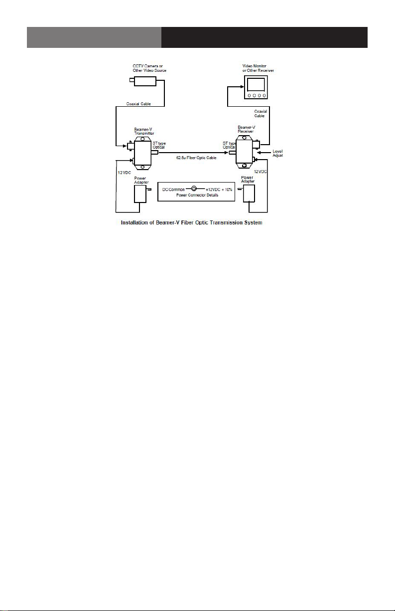
4. Is the proper 62.5 micron ber optic cable being used?
5. Is the length of ber optic cable longer than 1.5 miles? If so, a weak snowy picture may
result.
6. Are the ber optic connector ends free of any minute dust or dirt particles? If there is
any doubt, the use of a lint-free cloth moistened with a drop of alcohol should be used
to gently clean the optical surface.
If the above is correct and the system will still not operate properly, call our customer service
department for further assistance.
WARNING
This equipment generates, uses and can radiate radio frequency energy and if not
installed and used in accordance with the instruction manual, may cause interference
to radio communications. It has been tested and found to comply with the limits for
a Class A computing device pursuant to Subpart B of Part 15 of FCC Rules, which are
designed to provide reasonable protection against such interference when operated in a
commercial environment. Operation of this equipment in a residential area is likely to cause
interference, in which case the user at his own expense will be required to take whatever
measures may be required to correct the interference.
CE Information
Standards to which conformity is declared:
EMC EN 55022: 1994, CISPR 22: 1993, Class B Limit
EN 50082-1: 1992
IEC 801-2: 1991; IEC 801-3: 1984: IEC 801-4: 1988
FCC User Information
Operating Pointers | Troubleshooting

Page 7FiberLink Beamer-V™ User’s Manual
FiberLink Beamer-V™

• High performance plug and play products
• Stand alone and card cage versions available
• Solutions for most video, audio, and data formats
• Multimode and single mode versions
• Designed and manufactured in the USA
• Training and installation support available
• 24x7x365 technical support available
Proven Products, Unrivaled
Service, and Great Support
Artel Video Systems Corp.
5B Lyberty Way,
Westford, MA 01886 USA
T: 978-263-5775
F: 978-263-9755
sales@artel.com
customercare@artel.com
www.artel.com
All specifications subject to
change without notice. ©2016
Updated 02/16/2016
CS200-102021-00_H
Table of contents
Other Artel Extender manuals
Popular Extender manuals by other brands

Lindy
Lindy C5 PRO-300 Short user manual

CCi
CCi CC40 Operation and maintenance manual

LINK-MI
LINK-MI LM-HE150 user manual

GefenTV
GefenTV Extender for HDMI Long Range GTV-HDMI-CAT5LR user manual

Würth
Würth WTS 1800 Translation of the original operating instructions

Extron electronics
Extron electronics FOX 2G Tx AV Setup guide