Artel 3370-B7L User manual

WWW.ARTEL.COM
MANUAL
3G/HD/SD-SDI Transmission and
10/100 Ethernet & 2 Channels of
RS-Type Data over one single mode
or two multimode fibers
Installation and Operations
Manual
FiberLink
3370 Series

Page 2 FiberLink 3370 Series User’s Manual
FiberLink 3370 Series
Contents
Welcome .................................................................3
Features ..................................................................3
Package Contents.........................................................3
Technical Specications
Model Part Number Specications ....................................4
General Specications................................................4
Transmitter Specications ............................................5
Receiver Specications ...............................................6
Operating Loss Budgets ..............................................7
Maximum Useable Distance ..........................................7
Alarm Switch Settings.....................................................8
Installation Instructions ...................................................8
Data Conguration (Box Version) .........................................10
Baud Rate Settings ..................................................11
Ethernet Settings....................................................12
RS-Type Data Settings ...............................................12
Data Wiring .........................................................13
Data Conguration (Card Version) ........................................14
Baud Rate Settings ..................................................15
Ethernet Settings....................................................16
RS-Type Data Settings ...............................................16
Data Wiring .........................................................17
Indicator LEDs ...........................................................18
Operating Pointers .......................................................20
Troubleshooting .........................................................20
Maintenance and Repairs ................................................21
Certications ............................................................21
Accessories and Related Products ........................................22
Contents

Page 3FiberLink 3370 Series User’s Manual
FiberLink 3370 Series
Welcome
Thank you for purchasing Artel Video Systems’ FiberLink 3370 Series. The 3370 Series is used
to transmit 3G/HD/SD-SDI over one single mode ber or two multimode bers as well as
10/100 Ethernet and two channels of RS-Type data. The FiberLink 3370 series is compat-
ible with single mode or multimode ber. The system delivers noise-free transmission that
retains all of the signals’ initial parameters, regardless of ber optic cable attenuation. The
3370 Series also provides immunity to video pathological signals over the entire link bud-
get and operating temperature range.
Features
• Transmit up to 2 channels of bi-directional RS-Type data.
• Transmit 10/100 Base-T Ethernet
• All data and ethernet channels available simultaneously
• SDI signal is equalized and re-clocked prior to ber optic transmission
• Receiver features a re-clocked SDI output
• Immunity to pathological patterns over entire link budget and operating
temperature range
• Compliant with SMPTE 259M-2006, 292-2006, 424M-2006, 276M
• Supports one single mode ber or two multimode bers
• Supports 3G/HD/SD-SDI inputs with or without embedded audio and data
• 14 dB Optical Link Budget @ 2.97 Gbps
• Wide operating temperature range: -10º C to +50º C
• Available in Box and Card versions
• ST or LC connectors available
• Designed and Manufactured in the USA by Artel
Package Contents
• One FiberLink Unit (3370, 3371, 3372 or 3373)
• This User’s Manual
• One Ethernet Crossover Cable
Welcome | Features | Package Contents

Page 4 FiberLink 3370 Series User’s Manual
FiberLink 3370 Series
Model Part Number Specication
Unit Type Part Number
Transmitter Box (1 Fiber, SM) 3370-B7L (LC) 3370-B7S (ST)
Transmitter Rack Card (1 Fiber, SM) 3370-C7L (LC) 3370-C7S (ST)
Receiver Box (1 Fiber, SM) 3371-B7L (LC) 3371-B7S (ST)
Receiver Rack Card (1 Fiber SM) 3371-C7L (LC) 3371-C7S (ST)
Transmitter Box (2 Fiber, MM) 3372-B7L (LC) 3372-B7S (ST)
Transmitter Rack Card (2 Fiber, MM) 3372-C7L (LC) 3372-C7S (ST)
Receiver Box (2 Fiber, MM) 3373-B7L (LC) 3373-B7S (ST)
Receiver Rack Card (2 Fiber MM) 3373-C7L (LC) 3373-C7S (ST)
General Specications
Indicators
Power, Data Rate lock
(3G, HD, SD), Alarm (card version only),
RS-Data Channel 1, RS-Data Channel 2
& Ethernet LEDs on RJ-45 Connector
Box Version Dimensions 6.5 W x 1.15 H x 8 L (inches)
165 W x 29 H x 203 L (mm)
Weight approx. 1 lb.; 0.45 kg
Number of slots in 6000A card cage 2
Power 9-24 volts, AC or DC
3370: 4.8 watts, 16.4 BTU/Hr
3371: 4.65 watt s, 15.87 BTU/Hr
Operating Temperature -10ºC to +50ºC
MTBF 36,000 Hours
Data Specications:
Data Channels 2 Channels, Bi-Directional
Data Bandwidth DC to 115 Kb/sec, max.
Control Format Switch selectable RS-232, RS-422
& RS-485 (4 wire or 2 wire);
Protocols NRZ, NRZI, RZ, Manchester, Bi-phase
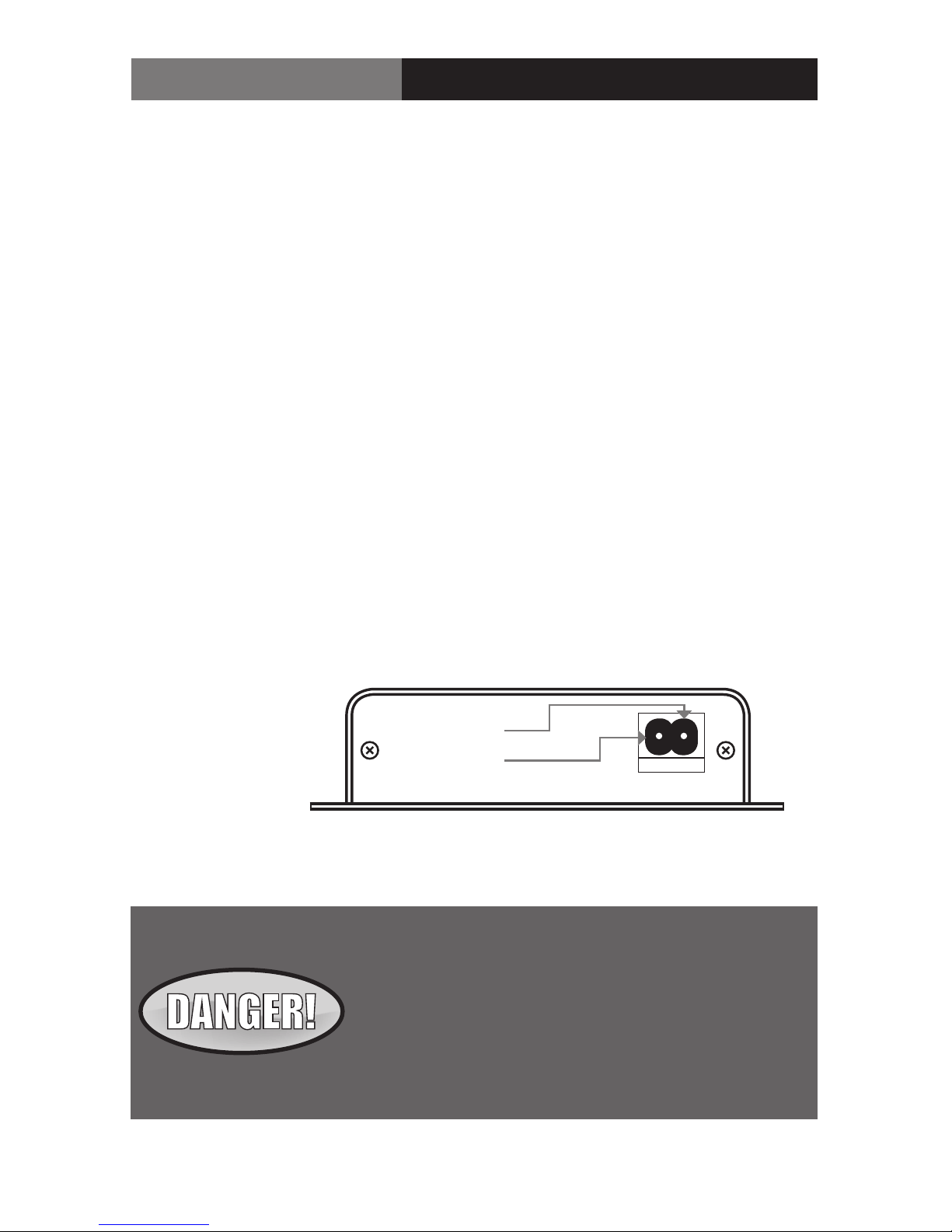
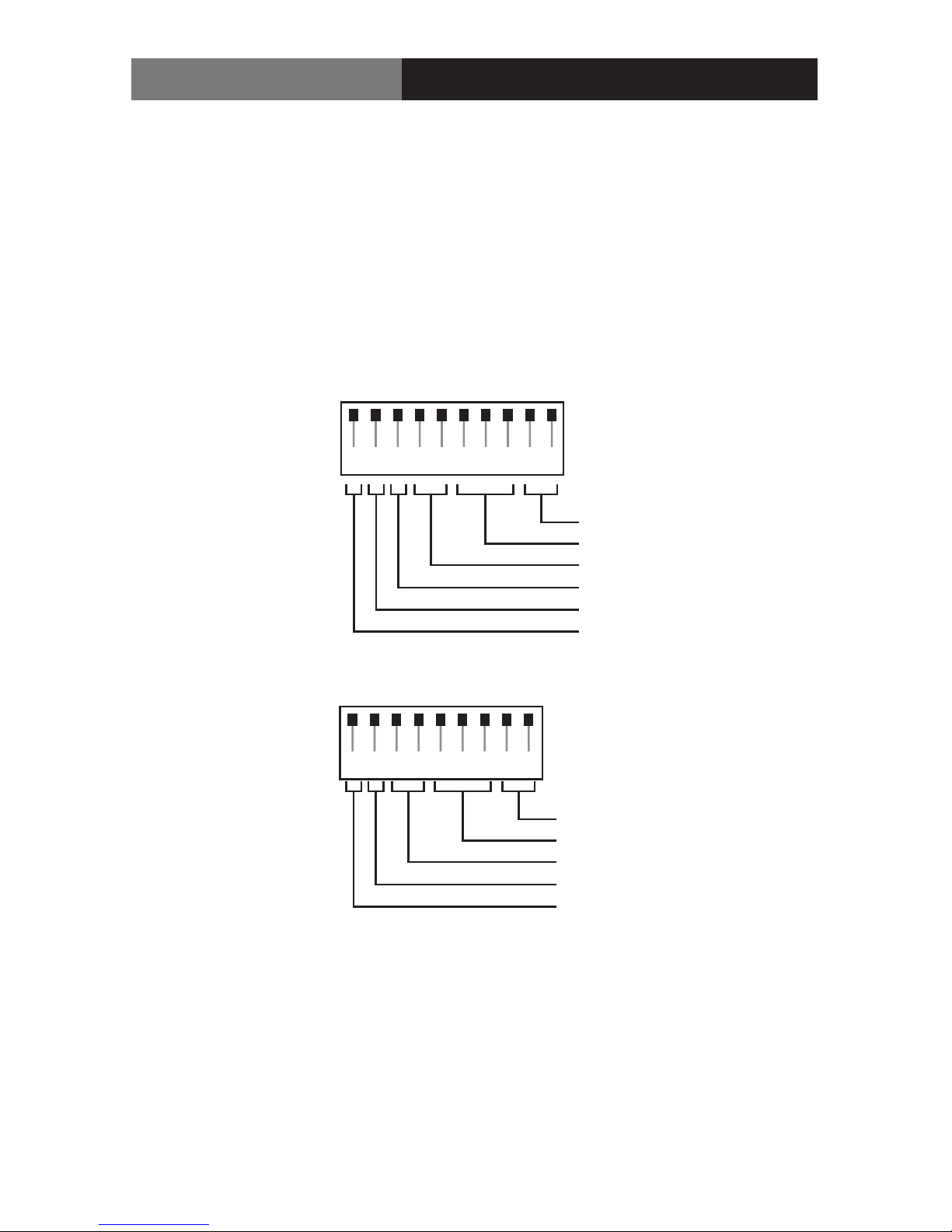
Signal Connectors: Removable terminal block Data
Technical Specications

Page 5FiberLink 3370 Series User’s Manual
FiberLink 3370 Series
Ethernet Specications:
Port: 10/100 Base-T, RJ-45 connector,
Congured as MDI
Speed: 10 Mbps & 100 Mbps Ethernet,
Switch Selectable
FiberLink 3370 Transmitter Specications:
Serial Video BNC Input Specications
Channels 2 Channels, Bi-Directional
Data Bandwidth DC to 115 Kb/sec, max.
Control Format Switch selectable RS-232, RS-422
& RS-485 (4 wire or 2 wire);
Protocols NRZ, NRZI, RZ, Manchester, Bi-phase
Signal Connectors: Removable terminal block
Gbps and 350m at 270 Mbps
Return Loss >10dB up to 2.97 Gbps
Fiber Optic Output Specications
Connector LC or ST
Wavelengths Used 1310nm, 1490nm, 1550nm
Emmiter Type FP Laser
Output Power (nominal) -4.5 dBm
SDI Re-clocking At 270 Mbps, 1.485 Gbps & 2.97 Gbps
Technical Specications

Page 6 FiberLink 3370 Series User’s Manual
FiberLink 3370 Series
FiberLink 3371 Receiver Specications:
Fiber Optic Input Specications
Connector LC or ST
Wavelength 1100 - 1620 nm
Minimum Input Sensitivity -17 dBm at 2.97 Gbps;
-22 dBm at 1.485 Gbps
-24 dBm at 270 Mbps;
Maximum Input Power 0 dBm
Serial Video BNC Output Specications
Number of Outputs 1
Signal Level 800mV ± 10%
DC Oset 0V ± 0.5V
Rise/Fall Time < 135 ps at 2.97 Gbps per SMPTE 424M;
< 270 ps at 1.485 Gbps per SMPTE 292;
0.4 ns to 1.5 ns at 270 Mbps
per SMPTE 259M
Overshoot < 10% of amplitude
Timing Jitter < 0.2 UI at 270 Mbps; < 1.0 UI at
1.485 Gbps; < 2.0 UI at 2.97 Gbps
with color bar signal
Alignment Jitter < 0.2 UI at 270 Mbps; < 0.2 UI at
1.485 Gbps; < 0.3 UI at 2.97 Gbps
with color bar signal
Re-clocking At 270 Mbps, 1.485 Gbps & 2.97 Gb
Technical Specications

Page 7FiberLink 3370 Series User’s Manual
FiberLink 3370 Series
FiberLink 3371 Receiver Specications:
Operating Loss Budget
Single Mode Fiber 0-14 dB at 2.97 Gbps
0-17 dB at 1.485 Gbps
0-20 dB at 270 Mbps
Multimode Fiber (62.5u) 0-14 dB at 2.97 Gbps
0-17 dB at 1.485 Gbps
0-20 dB at 270 Mbps
Multimode Fiber (50u) 0-14 dB at 2.97 Gbps
0-17 dB at 1.485 Gbps
0-20 dB at 270 Mbps
Maximum Useable Distance*
Single Mode Fiber 30 km at 2.97 Gbps
48 km at 1.485 Gbps
50 km at 270 Mbps
Multimode Fiber (62.5u) 0.8 km at 2.97 Gbps
1 km at 1.485 Gbps
2.5 km at 270 Mbps
Multimode Fiber (50u) 1 km at 2.97 Gbps
1.3 km at 1.485 Gbps
3 km at 270 Mbps
*Distance specications are approximate, based upon connecting a 3370 Transmitter to a 3370 Receiver, and are not guaranteed.
Artel cannot estimate or guarantee operating loss budgets when the 3370 Series is used with other, non-FiberLink devices.
Operating loss budget must not be exce
Operating Loss Budget | Maximum Useable Distance

Page 8 FiberLink 3370 Series User’s Manual
FiberLink 3370 Series
Installation Instructions
The FiberLink 3370 Series of ber optic transmission systems are ready for
immediate use and do not require any special tools or equipment.
The following instructions describe the typical installation procedure:
1) Connect the video source to the video input BNC connector on the transmitter unit.
2) (Optional) Connect your data connections as described in the Data Wiring
section of this manual.
3) Connect the video output cable to the video output BNC connectors on the
receiver unit.
4) (Optional) The ethernet port is congured as an MDI port. If you are not connecting
the 3370 Series to an auto-crossover ethernet port, you may need to use the ethernet
crossover cable supplied with the unit to connect to another MDI port.
5) (Optional) Connect your data connections as described in the Data Wiring
section of this manual.
Alarm Switch Settings | Installation Instructions
Alarm Switch Settings for the Transmitter Card
Switch Position Alarm Indication On O
1 Loss of Input Video Enabled Disabled
2 N/A N/A N/A
Alarm Switch Settings for the Receiver Card
Switch Position Alarm Indication On O
1 Loss of Optical Signal Enabled Disabled
2 N/A N/A N/A
Alarm Switch Settings & Options
The Rack Card version of this product has an additional red indicator LED that illuminates
when an alarm condition exists.
The rack card unit also provides an output to drive a model 6020A Alarm Sensing Module
which provides an audible tone and activates a set of contacts for external signaling
purposes.

Page 9FiberLink 3370 Series User’s Manual
FiberLink 3370 Series
Installation Instructions (cont.)
6) Connect the ber optic cable(s) to the transmitter and receiver units.
Note: when using two ber version, you must connect the transmitters Optical A to
the receivers Optical A and the transmitters Optical B to the receivers Optical B.
7) Connect the Universal Power Supply to the transmitter and receiver units.
For box versions using DC power, please refer to gure 1.
8) Congure your data preferences as described in the Data Conguration
section of this manual.
9) When power is applied, the green POWER LED should illuminate, indicating the
presence of operating power. The 3G/HD/SD RATE LEDs and the data LEDs will
give an indication as described in the Indicator LED’s and Alarm Circuitry section
of this manual.
10) The system should now be operational.
Note: The Rack Card version has an additional red LED for indicating the presence of an alarm
condition (loss of signal). Refer to Indicator LED’s and Alarm Circuitry sections of this manual.
Installation Instructions
The transmitting element in the FiberLink 3370 transmitter
unit contains a solid state Laser Diode located in the optical
connector. This device emits invisible infrared electromag-
netic radiation which can be harmful to human eyes. The
radiation from this optical connector, if viewed at close
range with no ber optic cable connected to the optical
connector, may be sucient intensity to cause
instantaneous damage to the retina of the eye. Direct
viewing of this radiation should be avoided at all times!
Figure 1:
Power Connector
DC Input Polarity
9-24 Volts
AC or DC
(+) Positive
( - ) Negative

Page 10 FiberLink 3370 Series User’s Manual
FiberLink 3370 Series Data Conguration (Box Version)
Data Conguration (Box Version):
The FiberLink 3370 Series box units have two dip switch panels, one with 10 switches, one
with 9. The rst panel, “Data Cong A”, represents the Ethernet and RS Channel A
conguration. The second panel,“Data Cong B”, represents RS Channel B conguration.
Note that all data channels are available simultaneously.
E123456789
DATA CONFIG A
Data Mode
Baud Rate
2 Wire/4 Wire Mode
Termination (Input 120 Ohm)
Termination (Output 120 Ohm)
Ethernet
Data Mode
Baud Rate
2 Wire/4 Wire Mode
Termination (Input 120 Ohm)
Termination (Output 120 Ohm)
123456789
DATA CONFIG B

Page 11FiberLink 3370 Series User’s Manual
FiberLink 3370 Series
Baud Rate Conguration
Data Conguration | Baud Rates (Box Version)
E123456789
DATA CONFIG A
123456789
DATA CONFIG B
2400
E123456789
DATA CONFIG A
123456789
DATA CONFIG B
19.2k
E123456789
DATA CONFIG A
123456789
DATA CONFIG B
38.4k
E123456789
DATA CONFIG A
123456789
DATA CONFIG B
57.6k
E123456789
DATA CONFIG A
123456789
DATA CONFIG B
76.8k
E123456789
DATA CONFIG A
123456789
DATA CONFIG B
4800
E123456789
DATA CONFIG A
123456789
DATA CONFIG B
9600

Page 12 FiberLink 3370 Series User’s Manual
FiberLink 3370 Series
Ethernet Congurations
RS-232
RS-485/422 4 Wire
RS-485 2 Wire T/R
E123456789
DATA CONFIG A
123456789
DATA CONFIG B
E123456789
E123456789
E123456789
DATA CONFIG A
DATA CONFIG A
DATA CONFIG A
123456789
123456789
123456789
DATA CONFIG B
DATA CONFIG B
DATA CONFIG B
E123456789
DATA CONFIG A
123456789
DATA CONFIG B
100 Base-T Ethernet
10 Base-T Ethernet
Data Conguration (Box Version)

Page 13FiberLink 3370 Series User’s Manual
FiberLink 3370 Series
Data Wiring:
RS-Type data wiring for the FiberLink 3370 Series is as follows:
Channel A
Channel A
Channel A
Channel A
Channel A
Channel B
Channel B
Channel B
Channel B
Channel B
Data Wiring (Box Version)
RS-232 Input RS-232 Output
G1234G1234 G1234G1234
RS-422/485 - 4 Wire Input RS-422/485 - 4 Wire Output
G1234G1234 G1234G1234
+ – + – + – + –
RS-485 - 2 Wire Input/Output
G1234G1234
+ – + –

Page 14 FiberLink 3370 Series User’s Manual
FiberLink 3370 Series Data Conguration (Card Version)
Data Conguration (Card Version):
The FiberLink 3370 Series card units have two dip switch panels with 10 switches. The
rst panel, “DATA CONFIG A”, represents the Ethernet and RS Channel A conguration. The
second panel,“DATA CONFIG B”, represents RS Channel B conguration. Note that all data
channels are available
simultaneously.
DATA CONFIG A
123456789
DATA CONFIG B
Data Mode
Baud Rate
2 Wire/4 Wire Mode
Termination (Input 120 Ohm)
Termination (Output 120 Ohm)
Ethernet
Not Used
Data Mode
Baud Rate
2/4 Wire Mode
Termination (Input 120 Ohm)
Termination (Output 120 Ohm)
12345678910
10

Page 15FiberLink 3370 Series User’s Manual
FiberLink 3370 Series
Baud Rate Conguration
Data Conguration | Baud Rates (Card Version)
2400
19.2k
38.4k
57.6k
76.8k
4800
9600
DATA CONFIG A
12345678910
DATA CONFIG B
12345678910
DATA CONFIG A
12345678910
DATA CONFIG B
12345678910
DATA CONFIG A
12345678910
DATA CONFIG B
12345678910
DATA CONFIG A
12345678910
DATA CONFIG B
12345678910
DATA CONFIG A
12345678910
DATA CONFIG B
12345678910
DATA CONFIG A
12345678910
DATA CONFIG B
12345678910
DATA CONFIG A
12345678910
DATA CONFIG B
12345678910

Page 16 FiberLink 3370 Series User’s Manual
FiberLink 3370 Series
Ethernet Congurations
RS-232
RS-485/422 4 Wire
RS-485 2 Wire T/R
10 Base-T Ethernet
100 Base-T Ethernet
Data Conguration (Card Version)
DATA CONFIG A
12345678910
DATA CONFIG B
12345678910
DATA CONFIG A
12345678910
S1
12345678910
DATA CONFIG A
12345678910
DATA CONFIG B
12345678910
DATA CONFIG A
12345678910
DATA CONFIG B
12345678910
DATA CONFIG A
12345678910
DATA CONFIG B
12345678910

Page 17FiberLink 3370 Series User’s Manual
FiberLink 3370 Series
Data Wiring:
RS-Type data wiring for the FiberLink 3370 Series card units is as follows:
Data Wiring (Card Version)
G1234
G1234
Data A
Data B
G1234 G1234
G1234 G1234
Data A Data A
Data B Data B
RS-232 Input RS-232 Output
RS-422/485 - 4 Wire Input RS-422/485 - 4 Wire Output
G1234 G1234
G1234 G1234
Data A Data A
Data B Data B
+ – + –
RS-485 - 2 Wire Input/Output
G1234
G1234
Data A
Data B
+ –

Page 18 FiberLink 3370 Series User’s Manual
FiberLink 3370 Series
Transmitter LEDs
LED Status Denition
Power On Indicates that correct power has been applied.
3G Rate O Indicates no 3G-SDI data rate lock
On Indicates 3G-SDI data rate lock at 2.97 Gbps or
2.97/1.001 Gbps
HD Rate O Indicates no HD-SDI data rate lock
On Indicates HD-SDI data rate lock at 1.485 Gbps or
1.485/1.001 Gbps
SD Rate O Indicates no SD-SDI data rate lock
On Indicates SD-SDI data rate lock at 270 Mbps
Data A O Indicates no data present
Blink Indicates data present (electrical or optical)
Data B O Indicates no data present
Blink Indicates data present (electrical or optical)
Alarm On Loss of input video (card version only)
Note: The 3G, HD and SD LEDs indicators are o when a non-standard signal is applied.
Indicator LEDs
The FiberLink 3370 Series has several indicator LEDs that are used to monitor the state of
the unit. Card versions have an additional Alarm LED.
Indicator LEDs

Page 19FiberLink 3370 Series User’s Manual
FiberLink 3370 Series
Receiver LEDs
LED Status Denition
Power On Indicates that correct power has been applied.
3G Rate O Indicates no 3G-SDI data rate lock
On Indicates 3G-SDI data rate lock at 2.97 Gbps or
2.97/1.001 Gbps
HD Rate O Indicates no HD-SDI data rate lock
On Indicates HD-SDI data rate lock at 1.485 Gbps or
1.485/1.001 Gbps
SD Rate O Indicates no SD-SDI data rate lock
On Indicates SD-SDI data rate lock at 270 Mbps
Data A O Indicates no data present
Blink Indicates data present (electrical or optical)
Data B O Indicates no data present
Blink Indicates data present (electrical or optical)
Alarm On Loss of optical signal (card version only)
Note: The 3G, HD and SD LEDs indicators are o when a non-standard signal is applied.
Indicator LEDs

Page 20 FiberLink 3370 Series User’s Manual
FiberLink 3370 Series
Operating Pointers
Remember to check attenuation of the ber optic cable. The system will only operate
properly if these specications fall within the range of the system’s loss budget.
Note: If no signal is applied to the 3370 Transmitter, no optical power will be present on the
3370 Transmitter’s output.
Troubleshooting
Multimode ber optic cable contains an optical ber with a light carrying “core”that is
only .0025 inches (62.5 microns) in diameter. Single mode ber optic cable has an even
smaller “core,” only .00032 to .0004 inches (8-10 microns). This is smaller than a human hair!
Therefore, any minute particles of dirt or dust can easily block the ber from accepting or
radiating light. To prevent this from happening, always use the provided dust caps when
ever optical connectors are exposed to air. It is also a good idea to gently clean the tip of an
optical connector with a lint-free cloth moistened with alcohol whenever dust is suspected.
The status of the LEDs should provide the rst clue as to the origin of any operational
failure. If these are o, it usually means that the ber is broken or has too much attenuation.
Next, be certain that the input and output signal connections are correct.
An optical power meter, such as the FiberLink 6615, a visible light source, such as the
FiberLink 6610, and a Three Wavelength Light Source, such as the FiberLink 6620, can
greatly assist and expedite troubleshooting of ber optic transmission systems and are
recommended tools all installers should have available.
Finally, although multimode and single mode devices may look the same, they will not
operate properly together. Using the wrong device or ber can easily add more attenuation
than specied, resulting in poor overall performance. It should be noted that some of our
ber optic products support both single mode and multimode ber in the same unit.
If, after reviewing the above possibilities, the system is still not operating, please contact
the Customer Service Department for further assistance. If you suspect your problem is
caused by the optics or the ber optic cable, and you have an optical power meter, please
take the appropriate measurements prior to contacting support.
Operating Pointers | Troubleshooting
This manual suits for next models
31
Table of contents
Other Artel Microphone System manuals