Artel FiberLink 7250 Series User manual

WWW.ARTEL.COM
MANUAL
Hi-Res RGB with Stereo Audio
Over Two Fibers
Installation and Operations
Manual
FiberLink
7250 Series

Page 2 FiberLink 7250 Series User’s Manual
FiberLink 7250 Series
Contents
Welcome .................................................................3
Features ..................................................................3
Package Contents.........................................................3
Technical Specications ...................................................4
Installation Instructions ...................................................6
Installation Procedure ................................................7
System Connections.................................................10
Alarm Switch Settings ................................................9
Indicator LEDs ...........................................................11
Operating Pointers and Troubleshooting..................................13
Maintenance and Repairs ................................................14
Contents

Page 3FiberLink 7250 Series User’s Manual
FiberLink 7250 Series
Welcome
The FiberLink 7250 Series is a transmitter/receiver pair that transmits a single channel of
RGBHV video (up to WUXGA) and two audio channels over two single mode or multimode
bers. It is available as a free-standing box unit or as a card version for use in the rackmount-
able 6000A card cage.
The system’s all digital encoding delivers noise-free transmissions that retain all of their ini-
tial parameters, regardless of ber optic cable attenuation. System operation may be easily
monitored using integral indicator LEDs on each unit that continuously signify the presence
of baseband video and audio signals.
Features
• Supports VGA, SVGA, XGA, WXGA, SXGA, SXGA+, UXGA and WUXGA (640 x 480 up to
1920 x 1200)
• Supports HDTV resolutions of 480p, 720p, 1080i and 1080p (RGBHV format only)
• Uses all digital processing with no compression for crystal clear signals and no colo
pixel skewing
• Requires no adjustments, equalization or de-skewing during installation
• Low audio/video skew, <300 uSec
• Small, lightweight, uses low power
• Unique feature allows the two bers to be cross connected without aecting
operation
• Fiber cables can be up to 20 meters dierent in length
• Complete, ready-to-install kits are available
• Available in box and card versions
• RoHS Compliant
Package Contents
• One FiberLink 7250 (Transmitter) and 7251 (Receiver)
• This User’s Manual
Welcome | Features | Package Contents

Page 4 FiberLink 7250 Series User’s Manual
FiberLink 7250 Series
Model Part Number Specication
Unit Type Part Number
Transmitter Box 7250-B7S
Transmitter Rack Card 7250-C7S
Receiver Box 7251-B7S
Receiver Rack Card 7251-C7S
Video Specications
Input Impedance RGB: 75 Ohms; H&V: Hi-Z
Input Level RGB: 714 mV p-p; H&V: 3 to 5 V p-p
H Sync Frequency Range 15 to 75 kHz
V Sync Frequency Range 30 to 85 Hz
Number of Video Channels Supported 1 RGBHV
RGB Format Supported RGB with separate H and V
Signal Connectors HD-15F
RGB Processing 24 bits, no compression or scaling
Audio Specications
Number of Audio Channels 2, unbalanced
Frequency Response +0/-0.5 dB, 20 Hz to 20 kHz
Input Impedance >24 k Ohms
Output Impedance <1 Ohm
Maximum Audio Level +10 dBu
THD+N 0.005%; 20 Hz - 20 kHz
SNR (A-Weighted) 95 dB
Channel Phase Dierential +/-0.1
o
Crosstalk Min. Min. 95 dB (1 kHz)
Signal Connectors 3.5mm Stereo jack
Audio to Video Di. Delay (skew) <300 uS
Technical Specications

Page 5FiberLink 7250 Series User’s Manual
FiberLink 7250 Series
Optical
Operating Wavelength 1310nm; MM or SM
Optical Fiber 62.5/125 microns MM,
50/125 microns MM or
8-10/125 microns SM
Optical Connector ST
Allowable Di. Fiber Length 20 meters
Class I Laser Product complies with FDA performance standard for laser products, Title 21,
Code of Federal Regulations, Sub-Chapter J
Loss Budget and Maximum Transmission Distance
Wavelength Loss Budget (in dB) Distance (in km)
1310 MM 0-15 0.75
1310 SM 0-15 30
*Distance specications are only approximate and are not guaranteed. Operating loss
budget must not be exceeded.
General Specifications
Operating Temp. Range -20 to +50 degrees C
Technical Specications

Page 6 FiberLink 7250 Series User’s Manual
FiberLink 7250 Series
Installation Instructions
The FiberLink 7250 Series transmission system is ready for immediate use. There are indica-
tor LEDs on the units for monitoring purposes. The following instructions describe the
typical installation procedure and the function of the LED indicators.
1. Connect the video source to the video input HD-15F connector on the transmitter unit.
2. Connect the video output on the receiver unit to the HD-15F connector.
3. Connect the ber optic cables between the two FiberLink units. Each ber may be con-
nected to either Optical 1 or Optical 2 on the receiver, regardless of which output (1or
2) each one is connected to on the transmitter. The system will still operate properly
if the bers are cross-connected. However, please note that any dierence in length
between the two bers must not exceed 20 meters.
4. Connect the audio input signals to the transmitter stereo jack and the audio output to
the receiver stereo jack.
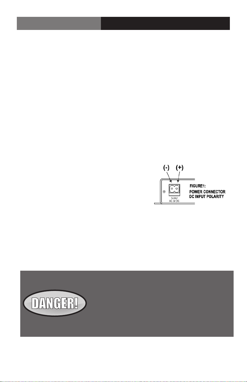
5. Apply power to both FiberLink units. For box versions using DC power connections,
refer to Figure 1.
6. When power is applied, the green POWER LED will
light, indicating the presence of operating power.
The VIDEO LED will give an indication as described
on page 7.
7. The green AUDIO LED will give an indication as
stated on page 7.
8. The system should now be operational.
Note that the rack card version has an additional red LED for indicating the presence of an
alarm condition (loss of signal). Refer to the table on the following page for alarm enables.
Installation Instructions
The transmitting element in the FiberLink 7240 and 7241
transmitter unit contains a solid state Laser Diode located
in the optical connector. This device emits invisible infrared
electromagnetic radiation which can be harmful to human
eyes. The radiation from this optical connector, if viewed
at close range with no ber optic cable connected to the
optical connector, may be sucient intensity to cause
instantaneous damage to the retina of the eye. Direct
viewing of this radiation should be avoided at all times!

Page 7FiberLink 7250 Series User’s Manual
FiberLink 7250 Series
Video Pin Out
Video Pin Out Transmitter Receiver
1 Red Red
2 Green Green
3 Blue Blue
4 N/C N/C
5 Ground Ground
6 Ground Ground
7 Ground Ground
8 Ground Ground
9 N/C N/C
10 Ground Ground
11 N/C N/C
12 N/C N/C
13 Hor. Sync. Out Hor. Sync Out
14 Vert. Sync Out Vert. Sync Out
15 N/C N/C
Video Pin Out
System Connections
The input and output connections for the FiberLink 7250 and 7251 units are as follows:
Audio Connector Transmitter & Receiver: 3.5mm stereo jack
Video Connector Transmitter & Receiver: HD-15F connector

Page 8 FiberLink 7250 Series User’s Manual
FiberLink 7250 Series Alarm Switch Settings
Alarm Switch Settings
Transmitter, Card Version Only
Switch Alarm Indication On O
Position
1 Loss of Video Enabled Disabled
2 N/A N/A N/A
Receiver, Card Version Only
Switch Alarm Indication On O
Position
1 Loss of Signal Enabled Disabled
2 Loss of Video Enabled Disabled
Transmitter LEDs
LED Status Definition
Power On (Green) Indicates that correct power has been applied
Video O Indicates no video detected on the input.
Blinking Green Indicates either H or V sync detected at the
input, but not both
Steady Green Indicates both H and V sync detected on the
input
Audio O Indicates no audio detected by the transmitter
unit
Alarm On (Red) Loss of video (rack card only)
Indicator LEDs
The stand-alone box versions of the FiberLink 7250 and 7251 units have three integral
indicator LEDs that are used to monitor the state of the units.
The rack card versions of these products have an additional red indicator LED that lights
when an alarm condition exists. The rack card unit also provides an output to drive a model
6020A Alarm Sensing Module which provides an audible tone and activates a set of contacts
for external signaling purposes.
The status of the LEDs are as follows:

Page 9FiberLink 7250 Series User’s Manual
FiberLink 7250 Series Indicator LEDs
Receiver LEDs
LED Status Denition
Power On (Green) Indicates that corrrect power has been applied
Video O Indicates no video detected over ber and, as a
result, no video present on the output.
Blinking Green Indicates either H or V sync detected at the
input, but not both
Steady Green Indicates both H and V sync detected over
the ber and, as a result, video present on
the output
Audio O Indicates no audio detected over ber and, as a
result, no active audio detected by the receiver
unit.
Blinking Green Indicates audio detected over ber and, as a
result, active audio detected by the receiver unit.
Data O No data detected to or from the receiver unit
Blinking Indicates active data detected to or from the
receiver unit
Alarm On (Red) Loss of video or optical signal (rack card only)

Page 10 FiberLink 7250 Series User’s Manual
FiberLink 7250 Series
Optical Fiber
The 7250 Series operates with most multimode (MM) and single mode (SM) optical fibers.
However, be aware that the type of fiber you use will aect the system’s loss budget and
the maximum transmission distance that it can support.
Troubleshooting
Multimode fiber optic cable contains an optical fiber with a light carrying “core” that is only
.0025 inches (62.5 microns) in diameter. Single mode fiber optic cable has an even smaller
“core,” only .00032 to .0004 inches (8-10 microns). This is smaller than a human hair!
Therefore, any minute particles of dirt or dust can easily block the fiber from accepting
or radiating light. To prevent this from happening, always use the provided dust caps
whenever optical connectors are exposed to air. It is also a good idea to gently clean the
tip of an optical connector with a lint-free cloth moistened with alcohol whenever dust is
suspected.
The status of the VIDEO and AUDIO indicator LEDs should provide the first clue as to the
origin of an operational failure. If these are o, it usually means that the fiber is broken or
has too much attenuation. Next, be certain that the input and output signal connections
are correct.
Operating Pointers | Troubleshooting

Page 11FiberLink 7250 Series User’s Manual
FiberLink 7250 Series
Maintenance and Repairs
The FiberLink 7250 Series transmission system has been manufactured using the latest
semiconductor devices and techniques that electronic technology has to oer. It has been
designed for long, reliable and trouble-free service and are not normally field repairable.
Should diiculty be encountered, Artel Video Systems maintains a complete service facility
to render accurate, timely and reliable service of all products.
The only maintenance that can be provided by the user is to ascertain that the optical
connectors are free of dust or dirt that could interfere with light transmission and that
electrical connections are secure and accurate. DANGER! Always turn o the transmitter’s
power before removing the optical fiber from either the transmitter or receiver unit.
All other questions or comments should be directed to our Customer Service Department.
It should be noted that many “problems” can easily be solved by a simple phone call.
Maintenance and Repairs

WWW.ARTEL.COM
MANUAL
• High performance plug and play products
• Stand alone and card cage versions available
• Solutions for most video, audio, and data formats
• Multimode and single mode versions
• Designed and manufactured in the USA
• Training and installation support available
• 24x7x365 technical support available
Proven Products, Unrivaled
Service, and Great Support
Artel Video Systems Corp.
5B Lyberty Way,
Westford, MA 01886 USA
T: 978-263-5775
F: 978-263-9755
sales@artel.com
customercare@artel.com
www.artel.com
All specifications subject to
change without notice. ©2016
Updated 04/28/2016
CS200-124819-00-E
This manual suits for next models
5
Table of contents
Other Artel Receiver manuals